

Page 1

FLOOR MOUNTED HEMIPLEGIC
REV011408
PARALLEL BARS
577, 580, 582, 590
Installation & Assembly
Page 2

Hemi Bars Floor Mounting & Assembly Instructions
Layout Base Post Assemblies on Floor:
Caution: Never install this product over any type of soft floor covering, such as carpet. Floor fasteners must anchor into
subfloor materials and can pass through floor tile or other solid floor coverings only. Failure to solidly anchor the unit may
result in unsafe and unreliable operation.
Note: Due to wide variances in floor and building construction, no mounting hardware or detailed hardware recommendations are provided. Consult an installation contractor or design professional who is familiar with you particular floor construction and materials. They can ensure compliance with the Uniform Building Code and any applicable local codes.
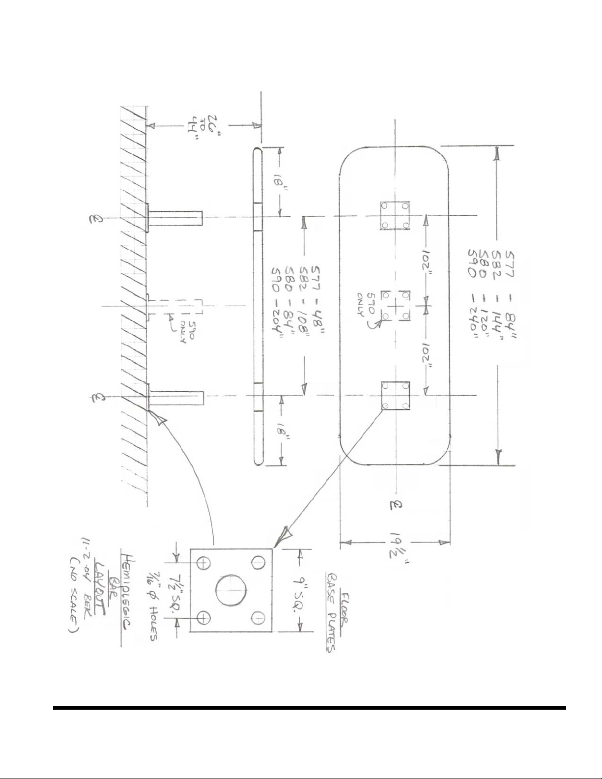
Determine permanent location for floor installation using baseplate layout provided. This diagram has dimensions for spacing the
baseplates on the floor.
These dimensions are to be maintained. The floor surface must be flat, or the baseplates must be shimmed so that the vertical posts
are perpendicular to the floor.
The base post alignment to each other must be squared and in-line as shown in the diagram.
Mount Post Assemblies to Floor:
Install proper floor fasteners according to manufacturers instructions and mount the Post Assemblies to the floor, All Plungers facing
outwards in the same direction. Do not tighten these Base Posts down completely at this time. They must be able to move.
Install Handrail Loop Assembly:
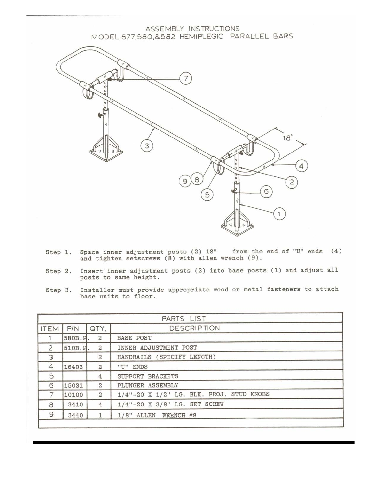
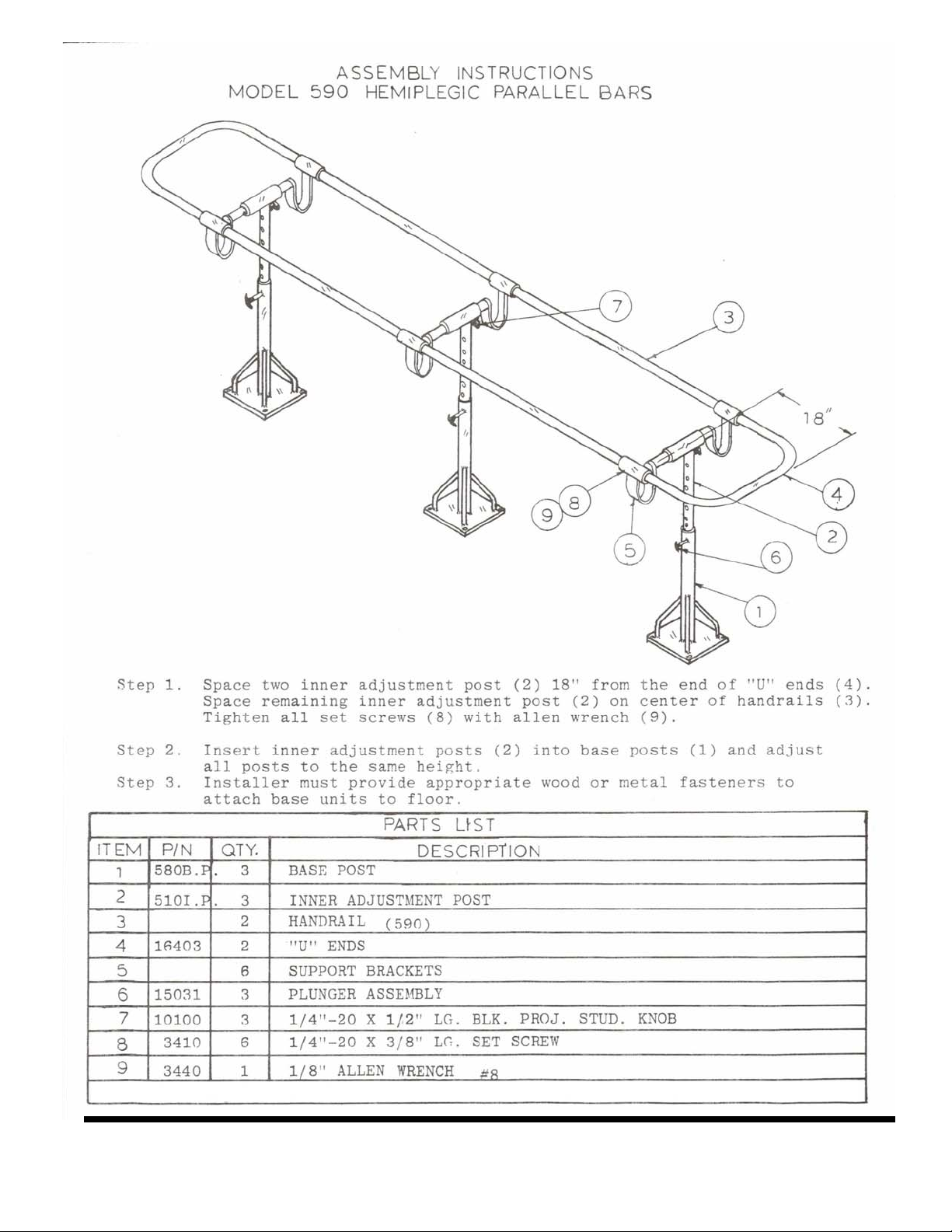
There are four (4) locations where the Handrail Loop is retained in place by an Allen setscrew. Loosen each Allen setscrew. They
must be loose enough to allow the Handrails to pass through without scratching the chrome plating. Their final location will be approximately 18 inches from the end of the loop [see diagrams].
The Handrail Loop is pre-mounted to the crosstubes and upper posts. Slide all upper posts down into the base posts at the same
time, being careful to insert the white guide bearings and black inserts. Pull back the height adjustment plungers and allow the handrail to "click" into the lowest adjustment setting.
Make adjustments to the Handrail Loop at this time. Ensure the crosstubes are located directly above the vertical posts and that there
is no binding. With all Posts and Plungers fully engaged at minimum height, tighten all floor mounting fasteners. Check that all
vertical posts are parallel to each other. Shim baseplates if necessary to achieve alignment.
Tighten all four (4) Handrail Loop Setscrews. Do not overtighten!
Floor Mount Final Assembly and Check:
After all Posts are secure to the floor, retract Plungers, then and raise and lower, checking for full Plunger engagement in each adjustment hole. Height adjustment must be done with both posts in unison, not one at a time. Failure to follow this procedure will
result in bent and/or loose components.
If for any reason a Plunger does not fully engage, loosen floor mounts and move Base Post slightly until Plunger engages. All Plungers should be fully tightened in posts. Retighten floor mounts.
Troubleshooting:
In the event the Bars do not function correctly, inspect all Plungers for tightness in their base post.
• Sticking or difficult to engage height adjustment is frequently remedied by performing the Base Post loosening and retightening
sequence described in the Final Assembly and Check section.
• If, after readjustment, the Plungers do not function correctly, inspect the black plastic post inserts. Replace any cracked, damaged
or missing inserts [contact factory for replacement parts and procedures].
• If all inserts are present and in good condition, inspect the Plunger Assembly. It may be worn and need replacement.
• Inserts that do not stay in place, may be shimmed with thin cello tape, sparingly applied to the outer diameter of the insert.
For detailed information regarding component replacement, contact Bailey Technical Support. Have your date of purchase and Bailey Dealer information handy for faster service.
Page 3
Page 4
Page 5
 Loading...