

Page 1
© 2019 Baileigh Industrial Holdings LLC
REPRODUCTION OF THIS MANUAL IN ANY FORM WITHOUT WRITTEN APPROVAL OF BAILEIGH INDUSTRIAL
negligence, or other occurrence.
Rev. 09/2019
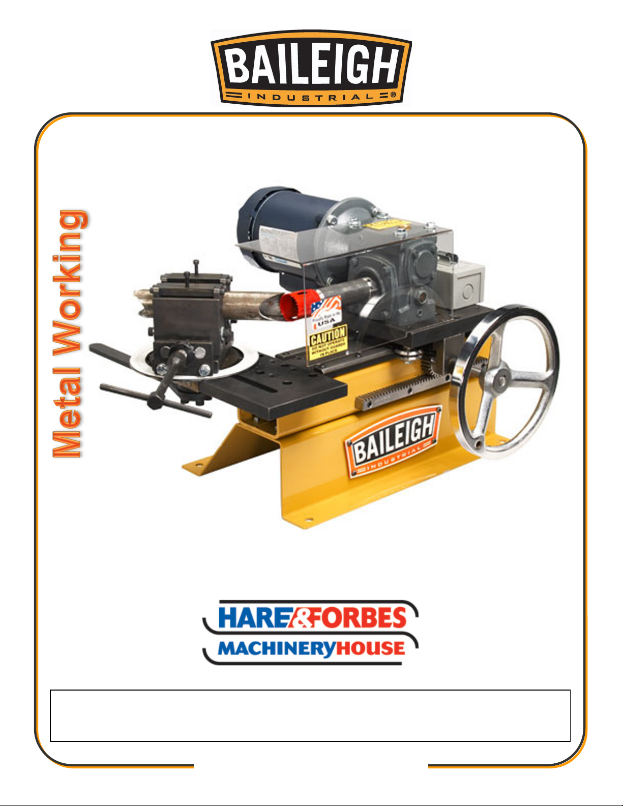
OPERATOR’S MANUAL
TUBE AND PIPE NOTCHER
MODEL: TN-300 (B8520)
HOLDINGS LLC IS PROHIBITED. Baileigh Industrial Holdings LLC, Inc. does not assume and hereby disclaims any
liability for any damage or loss caused by an omission or error in this Operator’s Manual, resulting from accident,
Page 2

Table of Contents
INTRODUCTION ............................................................................................................. 1
GENERAL NOTES .......................................................................................................... 1
SAFETY INSTRUCTIONS .............................................................................................. 2
SAFETY PRECAUTIONS ............................................................................................... 4
TECHNICAL SPECIFICATIONS ..................................................................................... 6
UNPACKING AND CHECKING CONTENTS .................................................................. 7
TRANSPORTING AND LIFTING .................................................................................... 8
INSTALLATION ............................................................................................................... 9
Anchoring the Machine ................................................................................................ 9
ELECTRICAL ................................................................................................................ 10
OPERATION ................................................................................................................. 12
Arbor Adapters .......................................................................................................... 13
MACHINE ADJUSTMENTS .......................................................................................... 14
LUBRICATION AND MAINTENANCE .......................................................................... 14
PARTS DIAGRAM ........................................................................................................ 15
Handwheel Assembly Parts Diagram ........................................................................ 15
Main Tube Assembly Parts Diagram ......................................................................... 16
Roller Base Assembly Parts Diagram ........................................................................ 17
Lock Nut Assembly Parts Diagram ............................................................................ 18
Vise Assembly Parts Diagram ................................................................................... 19
Electrical Box Assembly Parts Diagram .................................................................... 20
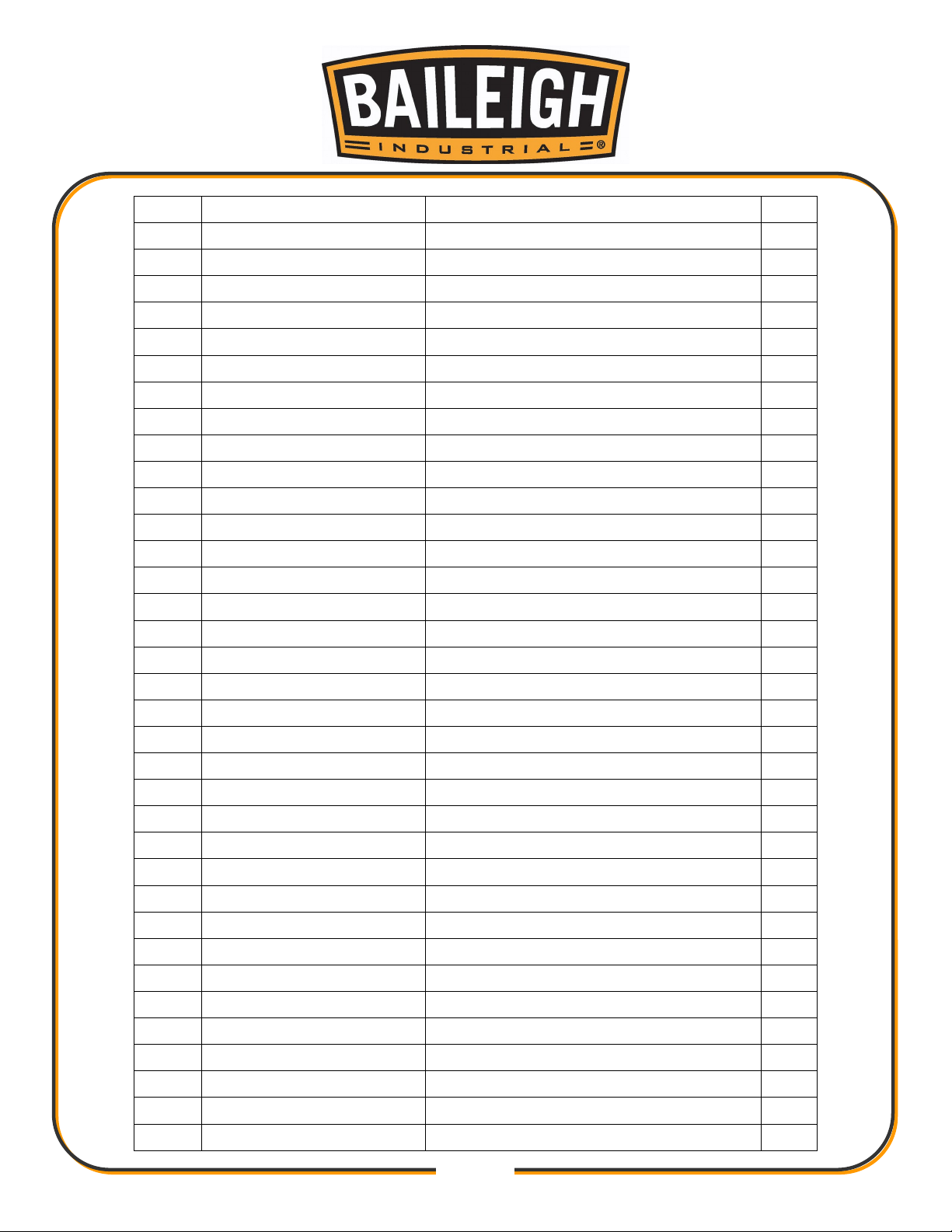
Parts List ................................................................................................................... 21
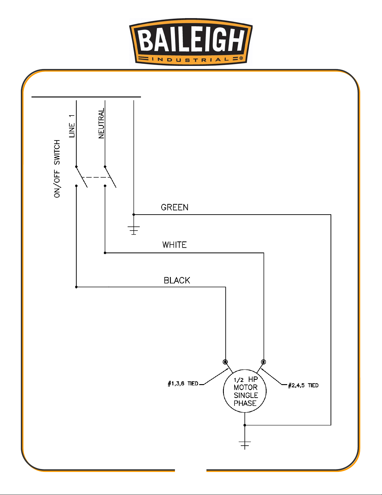
ELECTRICAL SCHEMATIC .......................................................................................... 24
Page 3
1
1
INTRODUCTION
The quality and reliability of the components assembled on a Baileigh Industrial Holdings LLC
machine guarantee near perfect functioning, free from problems, even under the most demanding
working conditions. However, if a situation arises, refer to the manual first. If a solution cannot be
found, contact the distributor where you purchased our product. Make sure you have the serial
number and production year of the machine (stamped on the nameplate). For replacement parts
refer to the assembly numbers on the parts list drawings.
In this manual you will find: (when applicable)
• Safety procedures
• Correct installation guidelines
• Description of the functional parts of the machine
• Capacity charts
• Setup and start-up instructions
• Machine operation
• Scheduled maintenance
• Parts lists
GENERAL NOTES
After receiving your equipment remove the protective container. Do a complete visual
inspection, and if damage is noted, photograph it for insurance claims and contact your
carrier at once, requesting inspection. Also contact your retailer and inform them of the
unexpected occurrence. Temporarily suspend installation.
Take necessary precautions while loading / unloading or moving the machine to avoid any
injuries.
Your machine is designed and manufactured to work smoothly and efficiently. Following proper
maintenance instructions will help ensure this. Try and use original spare parts, whenever
possible, and most importantly; DO NOT overload the machine or make any modifications.
Note: This symbol refers to useful information throughout the manual.
Page 4
2
2
DANGER
W
ARNING
CAUTION
NOTICE
IMPORTANT
PLEASE READ THIS OPERATORS MANUAL CAREFULLY
It contains important safety information, instructions, and necessary operating procedures.
The continual observance of these procedures will help increase your production and
extend the life of the equipment.
SAFETY INSTRUCTIONS
LEARN TO RECOGNIZE SAFETY INFORMATION
This is the safety alert symbol. When you see this symbol
on your machine or in this manual, BE ALERT TO THE
POTENTIAL FOR PERSONAL INJURY!
Follow recommended precautions and safe operating practices.
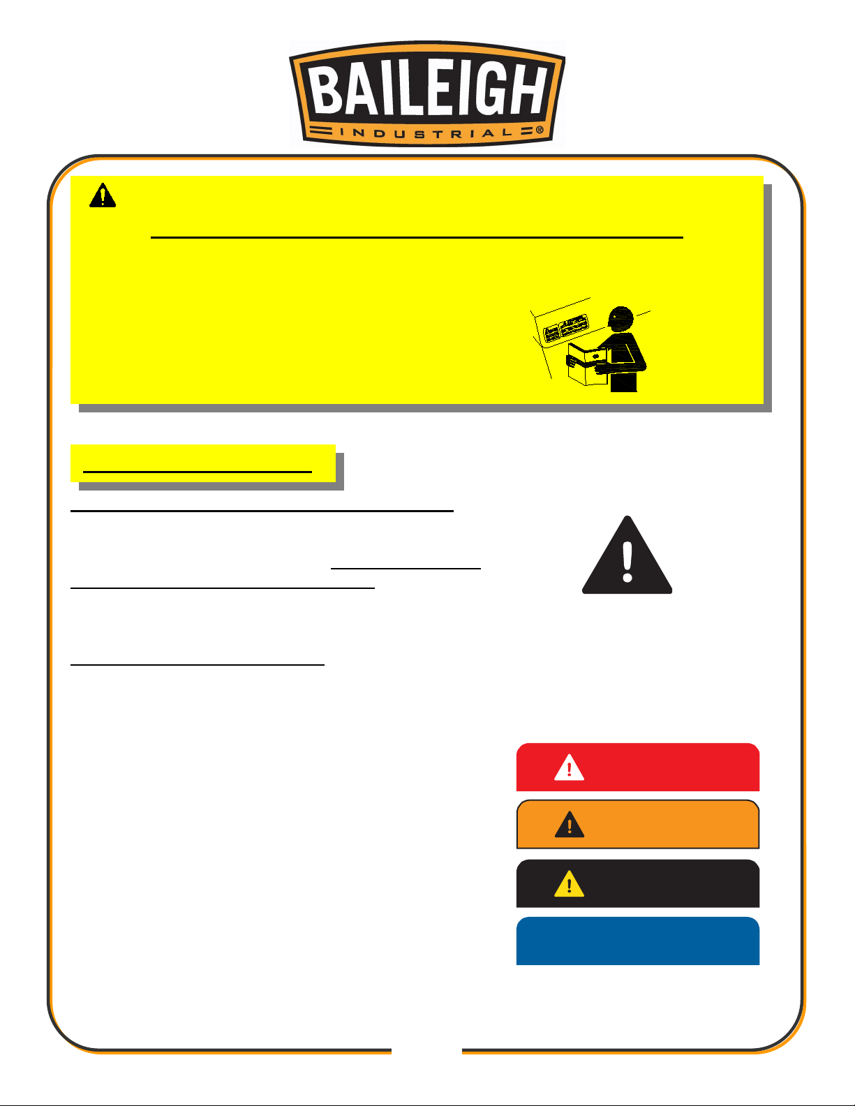
UNDERSTAND SIGNAL WORDS
A signal word – DANGER, WARNING, or CAUTION – is used with the safety alert symbol.
NOTICE, which is not related to personal injury, is used without a symbol.
DANGER: Indicates a hazardous situation which, if not
avoided, will result in death or serious injury.
WARNING: Indicates a hazardous situation which, if not
avoided, could result in death or serious injury.
CAUTION: Indicates a hazardous situation which, if not
avoided, could result in minor or moderate injury.
NOTICE: Indicates a situation which, if not avoided, could
result in property damage.
Page 5
3
3
SAVE THESE INSTRUCTIONS.
Refer to them often and use them to instruct others.
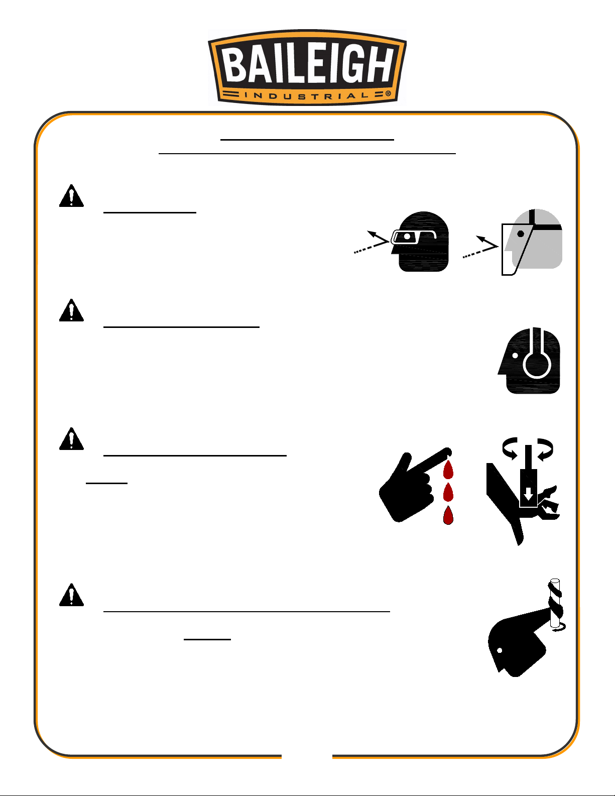
PROTECT EYES
Wear safety glasses or suitable eye protection
when working on or around machinery.
PROTECT AGAINST NOISE
Prolonged exposure to loud noise can cause impairment or loss of
hearing. Wear suitable hearing protective devices such as ear muffs or
earplugs to protect against objectionable or uncomfortable loud noises.
BEWARE OF PIERCING POINTS
NEVER place hands, fingers, or any part of your
body near rotating tools. Hole saws are very sharp
and can quickly pierce your fingers and hands.
Always wear heavy leather gloves when handling
these tools.
ENTANGLEMENT HAZARD – ROTATING SPINDLE
Contain long hair, DO NOT wear jewelry or loose fitting clothing.
Page 6
4
4
SAFETY PRECAUTIONS
Metal working can be dangerous if safe and proper operating procedures are not followed. As
with all machinery, there are certain hazards involved with the operation of the product. Using
the machine with respect and caution will considerably lessen the possibility of personal injury.
However, if normal safety precautions are overlooked or ignored, personal injury to the operator
may result.
Safety equipment such as guards, hold-downs, safety glasses, dust masks and hearing
protection can reduce your potential for injury. But even the best guard will not make up for poor
judgment, carelessness or inattention. Always use common sense and exercise caution in
the workshop. If a procedure feels dangerous, don’t try it.
REMEMBER: Your personal safety is your responsibility.
WARNING: FAILURE TO FOLLOW THESE RULES MAY RESULT IN
SERIOUS PERSONAL INJURY
Dear Valued Customer:
• All Baileigh machines should be used only for their intended use.
• Baileigh does not recommend or endorse making any modifications or alterations to a
Baileigh machine. Modifications or alterations to a machine may pose a substantial risk of
injury to the operator or others and may do substantial damage to the machine.
• Any modifications or alterations to a Baileigh machine will invalidate the machine’s warranty.
PLEASE ENJOY YOUR BAILEIGH MACHINE! ....PLEASE ENJOY IT SAFELY!
1. FOR YOUR OWN SAFETY, READ INSTRUCTION MANUAL BEFORE OPERATING THE
MACHINE. Learn the machine’s application and limitations as well as the specific hazards.
2. Only trained and qualified personnel can operate this machine.
3. Make sure guards are in place and in proper working order before operating
machinery.
4. Remove any adjusting tools. Before operating the machine, make sure any adjusting tools
have been removed.
5. Keep work area clean. Cluttered areas invite injuries.
6. Overloading machine. By overloading the machine, you may cause injury from flying parts.
DO NOT exceed the specified machine capacities.
7. Dressing material edges. Always chamfer and deburr all sharp edges.
Page 7

5
5
8. Do not force tool. Your machine will do a better and safer job if used as intended. DO NOT
use inappropriate attachments in an attempt to exceed the machines rated capacity.
9. Use the right tool for the job. DO NOT attempt to force a small tool or attachment to do the
work of a large industrial tool. DO NOT use a tool for a purpose for which it was not
intended.
10. Dress appropriate. DO NOT wear loose fitting clothing or jewelry as they can be caught in
moving machine parts. Protective clothing and steel toe shoes are recommended when
using machinery. Wear a restrictive hair covering to contain long hair.
11. Use eye and ear protection. Always wear ISO approved impact safety goggles. Wear a full-
face shield if you are producing metal filings.
12. Do not overreach. Maintain proper footing and balance at all times. DO NOT reach over or
across a running machine.
13. Stay alert. Watch what you are doing and use common sense. DO NOT operate any tool or
machine when you are tired.
14. Check for damaged parts. Before using any tool or machine, carefully check any part that
appears damaged. Check for alignment and binding of moving parts that may affect proper
machine operation.
15. Observe work area conditions. DO NOT use machines or power tools in damp or wet
locations. Do not expose to rain. Keep work area well lighted. DO NOT use electrically
powered tools in the presence of flammable gases or liquids.
16. Blade adjustments and maintenance. Always keep blades sharp and properly adjusted for
optimum performance.
17. Keep children away. Children must never be allowed in the work area. DO NOT let them
handle machines, tools, or extension cords.
18. Store idle equipment. When not in use, tools must be stored in a dry location to inhibit rust.
Always lock up tools and keep them out of reach of children.
19. DO NOT operate machine if under the influence of alcohol or drugs. Read warning
labels on prescriptions. If there is any doubt, DO NOT operate the machine.
20. DO NOT touch live electrical components or parts.
21. Turn off power before checking, cleaning, or replacing any parts.
22. Be sure all equipment is properly installed and grounded according to national, state, and
local codes.
23. Inspect power and control cables periodically. Replace if damaged or bare wires are
exposed. Bare wiring can kill!
24. DO NOT bypass or defeat any safety interlock systems.
25. Keep visitors a safe distance from the work area.
Page 8
6
6
TECHNICAL SPECIFICATIONS
Notching Capacity (OD)
Angle Adjustment
0 – 220°
Spindle Speed
200rpm
Power
240V / 50hz
Motor
1/2HP (.4kw) / 9A
Shipping Weight
Shipping Dimensions
15.8 – 76.2mm
120kg
1220 x 788 x 788mm
may not depict the actual color, labeling or accessories and may be intended to illustrate
technique only.
without prior notice due to improvements of our products.
Note: The photos and illustrations used in this manual are representative only and
Note: The specifications and dimensions presented here are subject to change
Page 9
7
7
UNPACKING AND CHECKING CONTENTS
SUFFOCATION HAZARD! Immediately discard any plastic
the machine. They have low flash points and can explode or cause fire.
GAS
Your Baileigh machine is shipped complete. Separate all parts from the packing material and
check each item carefully. Make certain all items are accounted for before discarding any
packing material.
WARNING:
bags and packing materials to eliminate choking and suffocation hazards to children
and animals.
If any parts are missing, DO NOT place the machine into service until the missing parts
are obtained and installed correctly.
Cleaning
WARNING: DO NOT USE gasoline or other petroleum products to clean
CAUTION: When using cleaning solvents work in a well-ventilated area.
Many cleaning solvents are toxic if inhaled.
Your machine may be shipped with a rustproof waxy coating and/or grease on the exposed
unpainted metal surfaces. Fully and completely remove this protective coating using a
degreaser or solvent cleaner. Moving items will need to be moved along their travel path to
allow for cleaning the entire surface. For a more thorough cleaning, some parts will occasionally
have to be removed. DO NOT USE acetone or brake cleaner as they may damage painted
surfaces.
Follow manufacturer’s label instructions when using any type of cleaning product. After cleaning,
wipe unpainted metal surfaces with a light coating of quality oil or grease for protection.
Important: This waxy coating is NOT a lubricant and will cause the machine to
stick and lose performance as the coating continues to dry.
Page 10
8
8
TRANSPORTING AND LIFTING
NOTICE: Lifting and carrying operations should be carried out by skilled workers, such as a
carefully, making sure the machine is well balanced.
truck operator, crane operator, etc. If a crane is used to lift the machine, attach the lifting chain
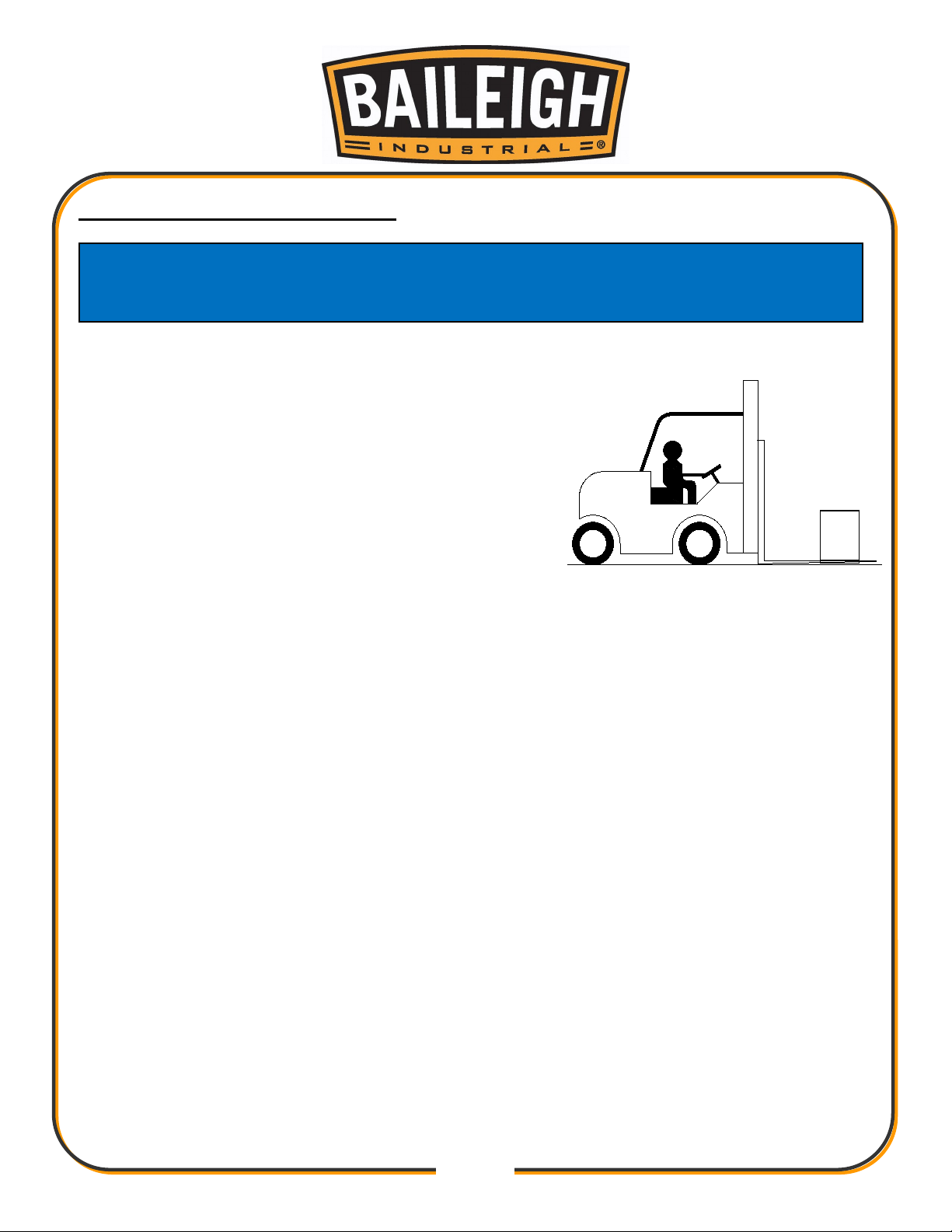
Follow these guidelines when lifting with truck or trolley:
• The lift truck must be able to lift at least 1.5 – 2 times
the machines gross weight.
• Make sure the machine is balanced. While
transporting, avoid rough or jerky motion, and
maintain a safe clearance zone around the transport
area.
• Use a forklift with sufficient lifting capacity and forks
that are long enough to reach the complete width of
the machine.
• Remove the securing bolts that attach the machine to the pallet.
• Approaching the machine from the side, lift the machine on the frame taking care that there
are no cables or pipes in the area of the forks.
• Move the machine to the required position and lower gently to the floor.
• Level the machine so that all the supporting feet are taking the weight of the machine and no
rocking is taking place.
Follow these guidelines when lifting crane or hoist:
• Always lift and carry the machine with the lifting holes provided at the top of the machine.
• Use lift equipment such as straps, chains, capable of lifting 1.5 to 2 times the weight of the
machine.
• Take proper precautions for handling and lifting.
• Check if the load is properly balanced by lifting it an inch or two.
• Lift the machine, avoiding sudden accelerations or quick changes of direction.
• Locate the machine where it is to be installed, then lower slowly until it touches the floor.
Page 11

9
9
INSTALLATION
IMPORTANT:
Consider the following when looking for a suitable location to place the machine:
• Overall weight of the machine.
• Weight of material being processed.
• Sizes of material to be processed through the machine.
• Space needed for auxiliary stands, worktables, or other machinery.
• Clearance from walls and other obstacles.
• Maintain an adequate working area around the machine for safety.
• Have the work area well illuminated with proper lighting.
• Keep the floor free of oil and make sure it is not slippery.
• Remove scrap and waste materials regularly, and make sure the work area is free from
obstructing objects.
• If long lengths of material are to be fed into the machine, make sure that they will not extend
into any aisles.
• LEVELING: The machine should be sited on a level, concrete floor. Provisions for securing it
should be in position prior to placing the machine. The accuracy of any machine depends on
the precise placement of it to the mounting surface.
• FLOOR: This machine distributes a large amount of weight over a small area. Make certain
that the floor is capable of supporting the weight of the machine, work stock, and the
operator. The floor should also be a level surface. If the unit wobbles or rocks once in place,
be sure to eliminate by using shims.
• WORKING CLEARANCES: Take into consideration the size of the material to be
processed. Make sure that you allow enough space for you to operate the machine freely.
• POWER SUPPLY PLACEMENT: The power supply should be located close enough to the
machine so that the power cord is not in an area where it would cause a tripping hazard. Be
sure to observe all electrical codes if installing new circuits and/or outlets.
Anchoring the Machine
This machine is generally mounted on a bench top. If you intend to mount this machine on a
workbench be aware of the following:
• Make sure the workbench is properly reinforced to support the weight.
• The strongest mounting option is where the holes are drilled all the way through the
workbench and the machine is secured with bolts, washers, and nuts.
Page 12
10
10
ELECTRICAL
CAUTION: HAVE ELECTRICAL UTILITIES CONNECTED TO MACHINE BY
A CERTIFIED ELECTRICIAN!
Check if the available power supply is the same as listed on the machine nameplate.
WARNING: Make sure the grounding wire (green) is properly connected
to avoid electric shock. DO NOT switch the position of the green grounding wire if any
electrical plug wires are switched during hookup.
Power Specifications
Your machine is wired for 240 volts, 50hz alternating current. Before connecting the machine to
the power source, make sure the power source is OFF.
Before switching on the power, you must check the voltage and frequency of the power to see if
they meet with the requirement, the allowed range for the voltage is ±5%, and for the frequency
is ±1%.
Considerations
• Observe local electrical codes when connecting the machine.
• The circuit should be protected with a time delay fuse or circuit breaker with an amperage
rating slightly higher than the full load current of machine.
• A separate electrical circuit should be used for your machines. Before connecting the motor
to the power line, make sure the switch is in the “OFF” position and be sure that the electric
current is of the same characteristics as indicated on the machine.
• All line connections should make good contact. Running on low voltage will damage the
motor.
• In the event of a malfunction or breakdown, grounding provides a path of least resistance for
electric current to reduce the risk of electric shock. This machine is equipped with an electric
cord having an equipment-grounding conductor and a grounding plug. The plug must be
plugged into a matching outlet that is properly installed and grounded in accordance with all
local codes and ordinances.
WARNING: In all cases, make certain the receptacle in question is
properly grounded. If you are not sure, have a qualified electrician check the
receptacle.
Page 13
11
11
• Improper connection of the equipment-grounding conductor can result in risk of electric
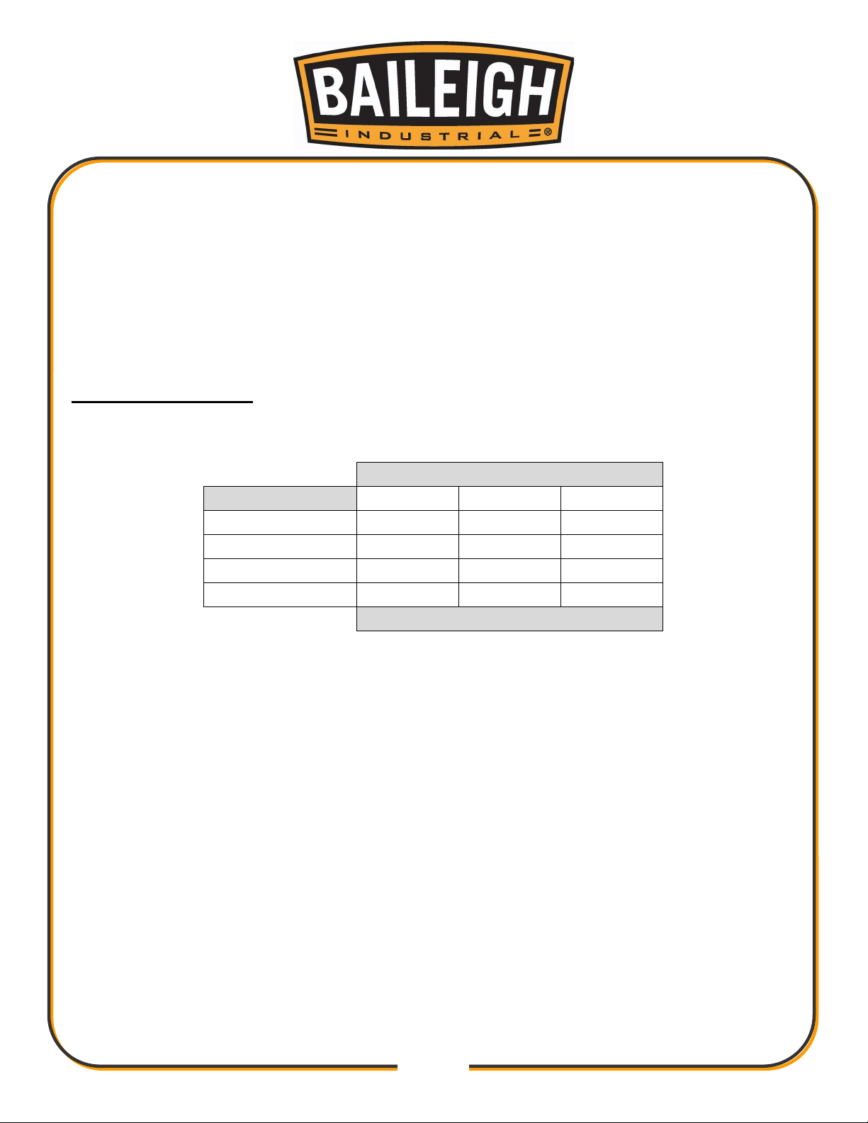
LENGTH
AMP RATING
25ft
50ft
100ft
1-12
16
16
14
13-16
14
12
12
17-20
12
12
10
21-30
10
10
No
WIRE GAUGE
shock. The conductor with insulation having an outer surface that is green with or without
yellow stripes is the equipment-grounding conductor. If repair or replacement of the electric
cord or plug is necessary, do not connect the equipment-grounding conductor to a live
terminal.
• Check with qualified electrician or service personnel if the grounding instructions are not
completely understood, or if in doubt as to whether the machine is properly grounded.
• Repair or replace damaged or worn cord immediately.
Extension Cord Safety
Extension cord should be in good condition and meet the minimum wire gauge requirements listed
below:
An undersized cord decreases line voltage, causing loss of power and overheating. All cords
should use a ground wire and plug pin. Replace any damaged cords immediately.
Page 14
12
12
OPERATION
CAUTION: Always wear proper eye protection with side shields, safety
footwear, and leather gloves to protect from burrs and sharp edges.
When handling large heavy materials make sure they are properly supported.
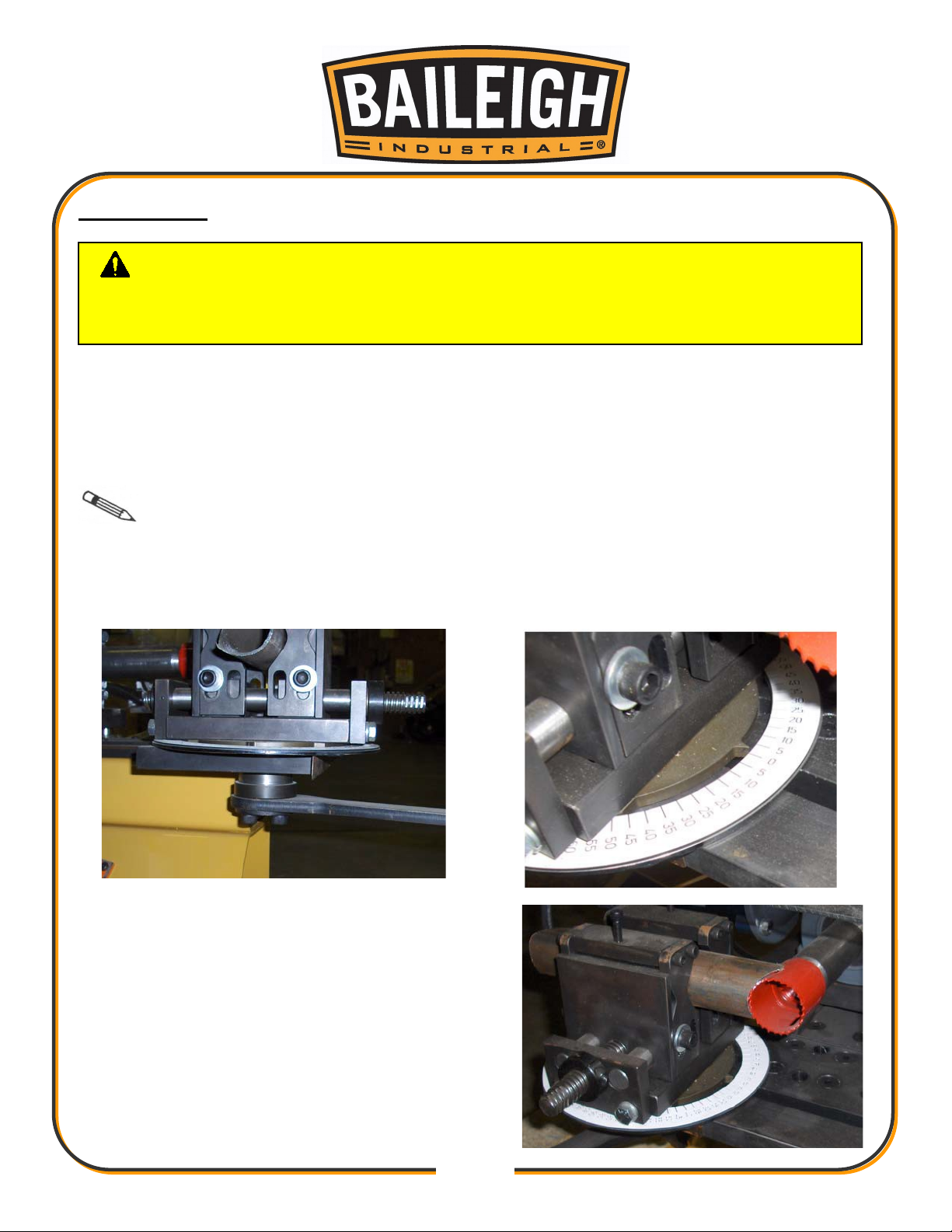
This notcher uses replaceable hole-saws to produce quality notches in various materials at
almost unlimited angles.
1. Before notching can take place, the correct hole-saw must be selected to match the material
being notched.
Note: Only heavy duty hole saws can be used. The hole-saws with solid backing
plates are best. The stamped and formed hole-saws are not rigid enough for this machine. The
hole-saws simply screw onto the arbor.
2. Loosen the vise lock lever and rotate to the desired notch angle and re-tighten.
3. Select the material and insert it into the vise.
Leave the minimum required material hanging
beyond the vise.
Page 15
13
13
4. Start the notcher with the on/off switch.
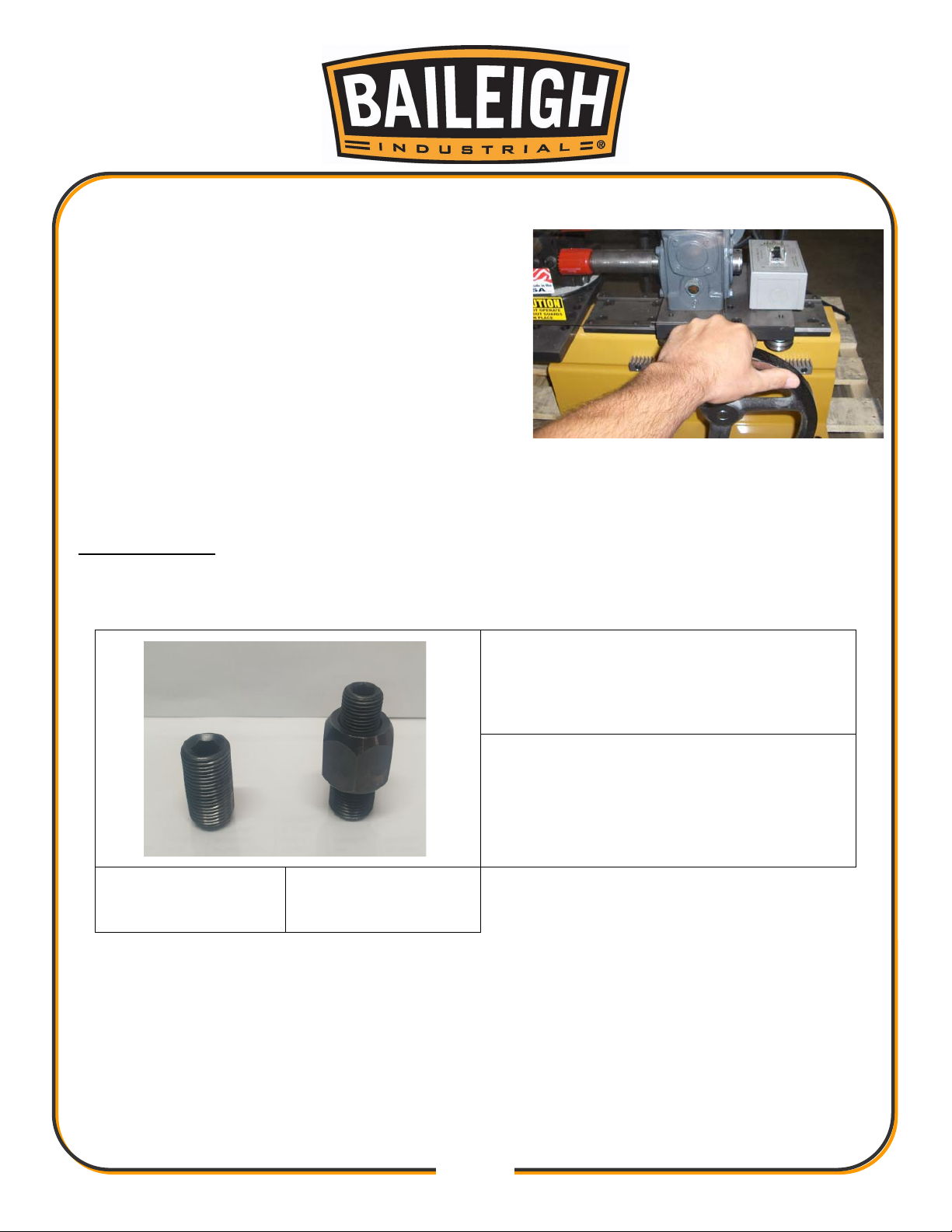
Standard Adapter.
saws.
Reducer Adapter.
saws.
5. Grasp the feed hand wheel and SLOWLY feed
the hole-saw into the tubing. Continue feeding
completely through the material to complete the
notch.
6. The speed of the hole-saw is fixed and is correct
for most sizes.
7. If you encounter chatter, feed slower and make
sure the “V” rollers have enough tension on them.
The feed hand wheel should have a slight
resistance set by the “V” rollers; if the rollers
should loosen up, they will need to be adjusted to give them some resistance.
Arbor Adapters
When setting up the notcher, use the correct arbor to saw adapter to fit the size and manufacturer
of the hole saw being used.
Used with most hole
Hole Saw End
Arbor End
Used with small hole
Page 16
14
14
MACHINE ADJUSTMENTS
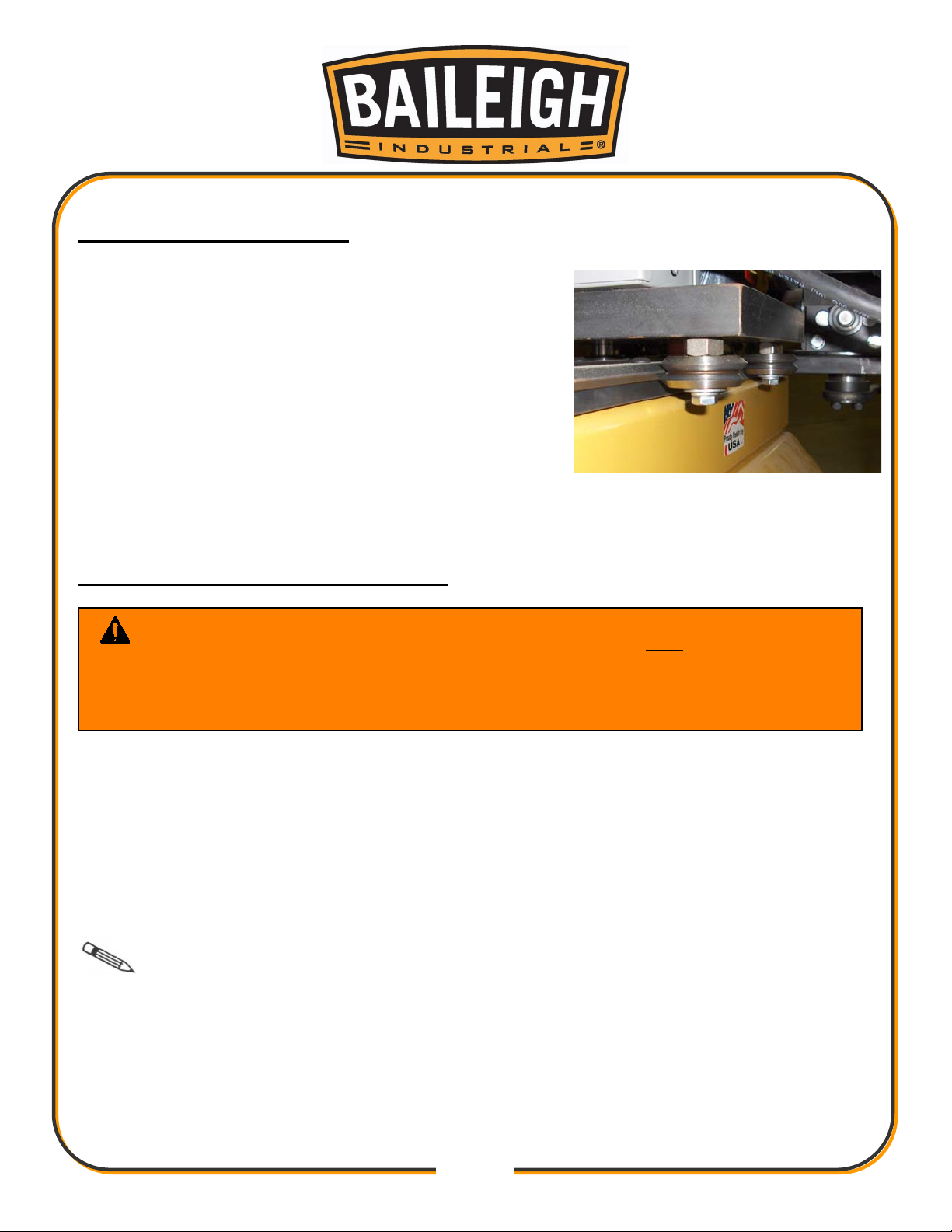
Two of the rollers have an eccentric tension adjuster, they
are the ones that have a hexed shaped portion beneath
the “V” roller.
1. To adjust, loosen the center bolt using a 1/2" wrench,
and then with another wrench to hold the hex, rotate
the hex slightly and the roller will either tighten or
loosen as the hex eccentric is turned.
2. Give it a little tension and tighten the center screw, try
the feed handwheel and check the resistance. The
rollers should NOT be able to rotate by hand, that
would be too loose.
LUBRICATION AND MAINTENANCE
WARNING: Make sure the electrical disconnect is OFF before working on
the machine.
Maintenance should be performed on a regular basis by qualified personnel.
Always follow proper safety precautions when working on or around any machinery.
• Check daily for any unsafe conditions and fix immediately.
• Check that all nuts and bolts are properly tightened.
• On a weekly basis clean the machine and the area around it.
• Lubricate threaded components and sliding devices.
• Apply rust inhibitive lubricant to all non-painted surfaces.
Note: Proper maintenance can increase the life expectancy of your machine.
Page 17
15
15
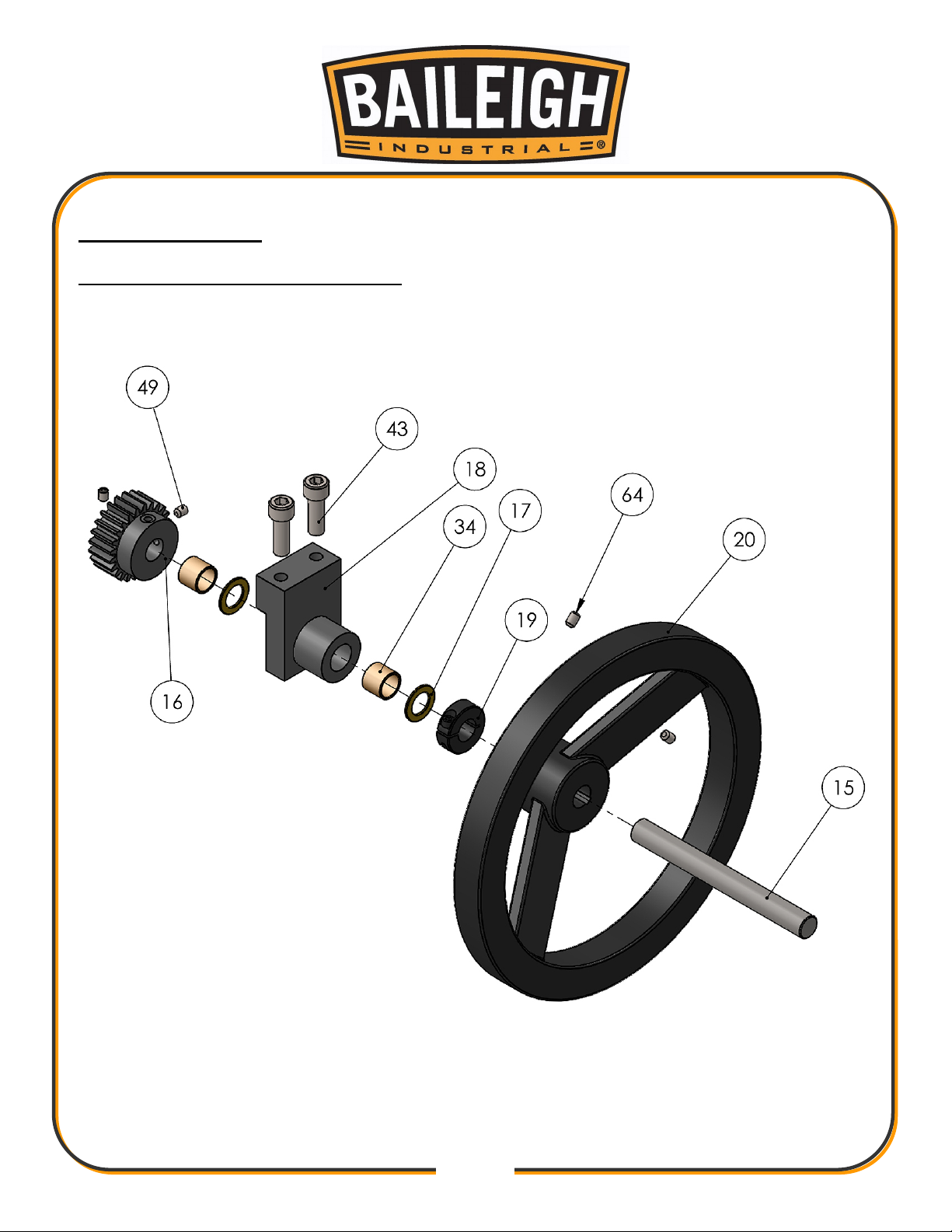
PARTS DIAGRAM
Handwheel Assembly Parts Diagram
Page 18
16
16
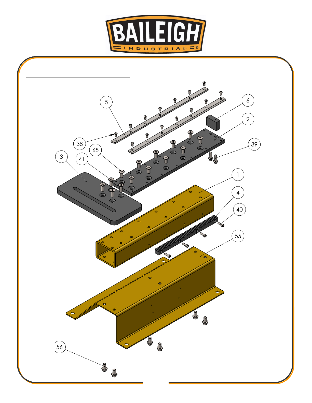
Main Tube Assembly Parts Diagram
Page 19
17
17
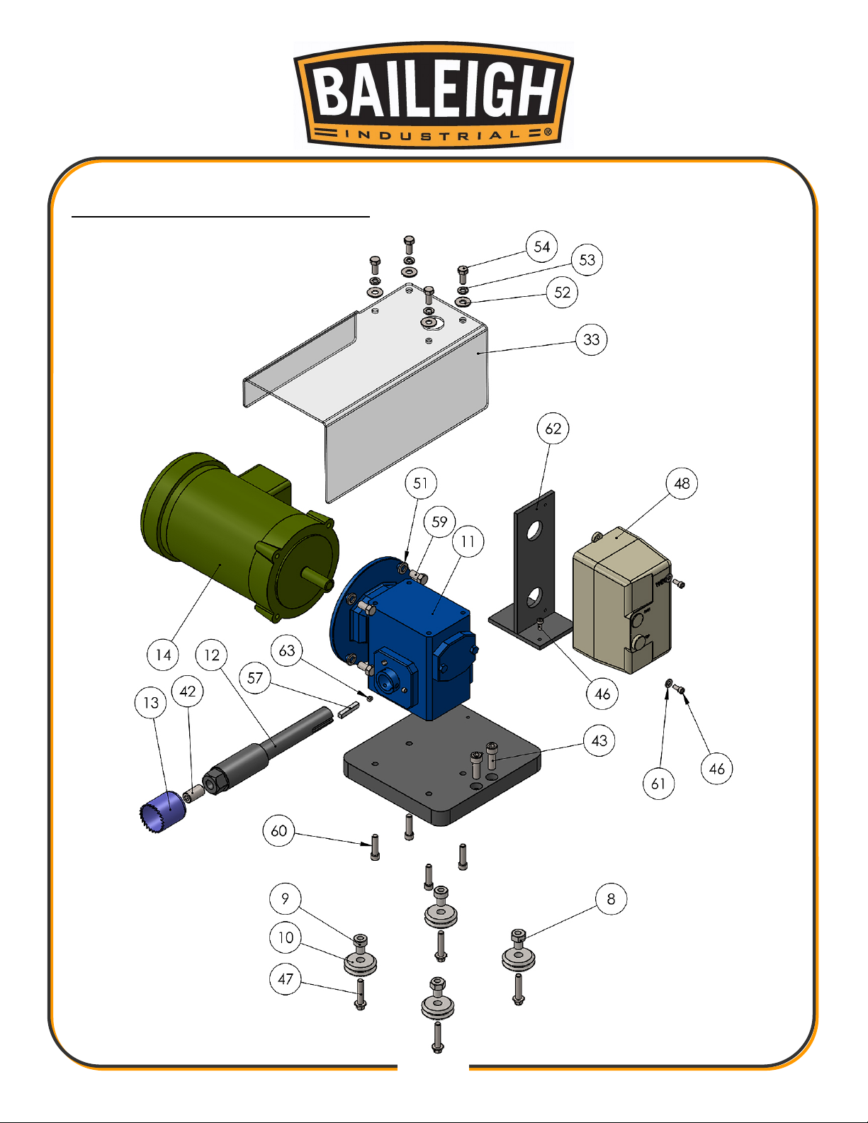
Roller Base Assembly Parts Diagram
Page 20
18
18
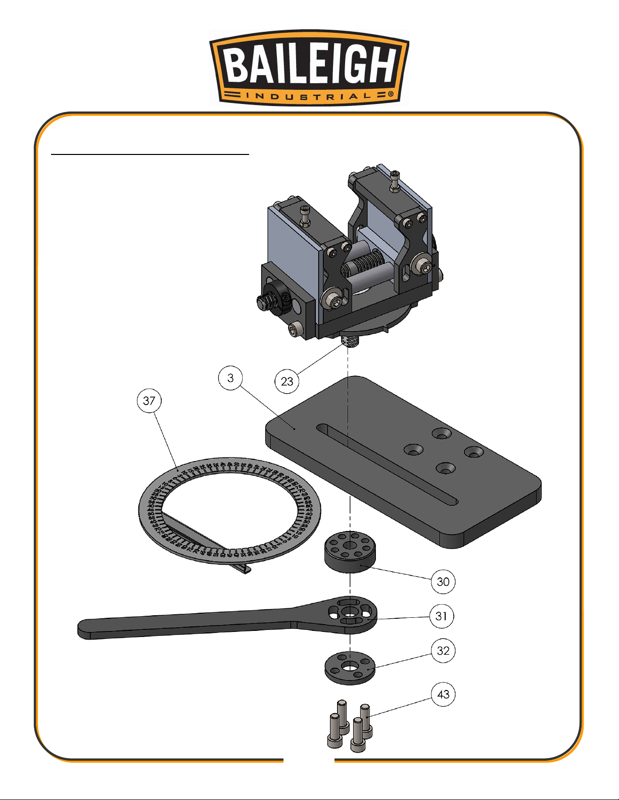
Lock Nut Assembly Parts Diagram
Page 21
19
19
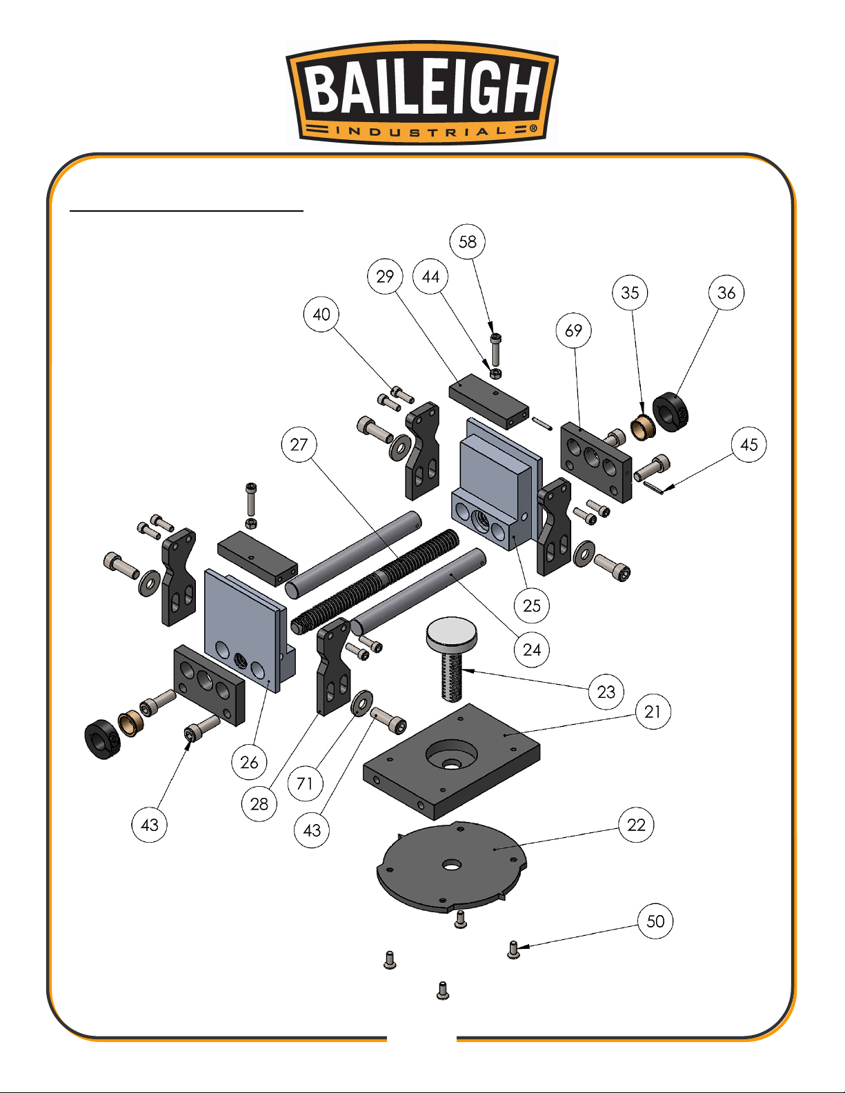
Vise Assembly Parts Diagram
Page 22
20
20
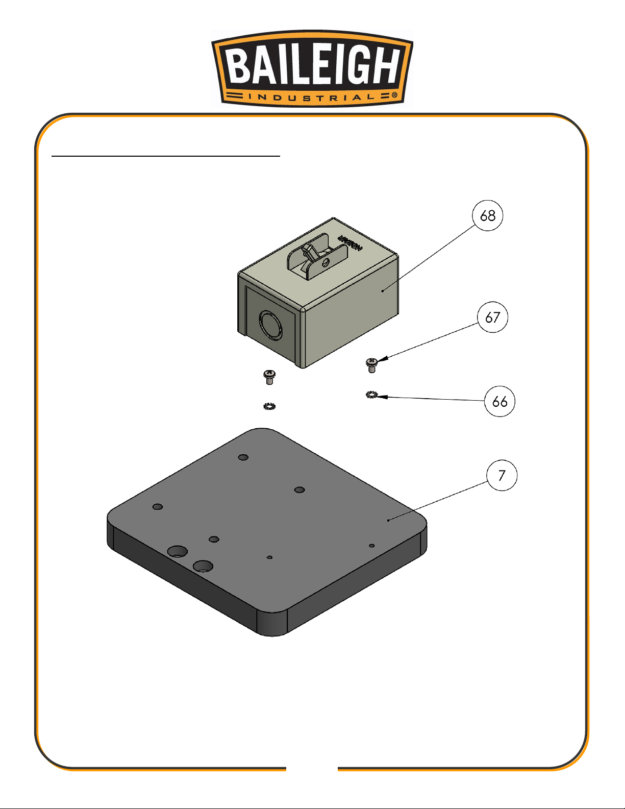
Electrical Box Assembly Parts Diagram
Page 23
21
21
Item
Part Number
Description
Qty.
1
ME-M600-6A001
Main Tube
1 2 ME-M600-6A003
Track Mount
1 3 ME-M600-6A005
Slide Plate
1 4 ME-M600-6A009
Gear Rack
1
5
M600-6A026
Vee Track 19"
2 6 ME-M600-6A017
Stop Block
1 7 ME-M600-6A004
Slide Plate
1 8 PP-0202-ME
Adjusting Bushing Wx3
2 9 PP-0203-ME
Non-Adjusting Bushing W3
2
10
PP-0201
V-Roller
4
11
PP-0962
Gearbox
1
12
ME-M600-7A001
Saw Arbor
1
13
PP-0971
1.75 Holesaw
1
14
PP-1074
1/2hp 1 Phase Motor
1
15
M600-7A003
Axle Shaft
1
16
ME-M600-7A004
24 Tooth Gear
1
17
PP-0168
.625 ID x 1.0 OD x .0625
2
18
ME-M600-6A006
Shaft Mount
1
19
PP-0958
5/8" Clamp Collar
1
20
PP-1031
10" Handwheel
1
21
ME-M900-6A047
Vise Base
1
22
ME-M900-6A052
Pointer Disc
1
23
M900-7A011
Vise Lock Stud
1
24
M900-7A014
Vise Slide Shaft
2
25
ME-M900-6A055
Vise Slide Block (L.H.)
1
26
ME-M900-6A049
Vise Slide Block (R.H.)
1
27
M900-7A012
Double Vise Screw
1
28
M900-6A050
Vise Jaw
4
29
ME-M900-6A051
Vise Cross Bar
2
30
ME-M900-6A042
Vise Lock Nut
1
31
M900-6A040
Lock Lever
1
32
M900-6A041
Lock Cap
1
Parts List
Page 24
22
22
Item
Part Number
Description
Qty.
33
M600-6A008
Lexan Guard
1
34
PP-0997
3/4 OD x 5/8 ID x 5/8 Lg Bush
2
35
PP-1063
.75 ID x .875 OD x .5 Flange Bushing
2
36
PP-0090
3/4" Split Collar
2
37
M600-5A002
Degree Dial
1
38
BSM-0138
M6 x 1.0 x 12 BHCS
14
39
BSM-0053
M8 x 1.25 x 25 Hex Flg
2
40
BSM-0002
M6 x 1.0 x 20 SHCS
12
41
BSM-0139
M10 x 1.5 x 30 FHCS
4
42
BS-0261
5/8-18 x 1.25 Set Screw
1
43
BSM-0016
M10 x 1.5 x 30 SHCS
2
44
BSM-0182
M6 x 1.0 Hex Nut
2
45
BS-0088
1/8 x 1 Slotted Spring Pin
2
46
BSM-0115
M5 x 0.8 x 12 SHCS
4
47
BSM-0054
M8 x 1.25 x 40 Hex Flg
4
48
PP-1295
CE On/Off Switch
1
49
BSM-0084
M6 x 1.0 x 8 Set Screw
2
50
BSM-0122
M6 x 1.0 x 16 FHCS
4
51
BS-0074
3/8 Lock Washer
4
52
BS-0082
5/16 Flat Washer
4
53
BS-0073
5/16 Lock Washer
4
54
BS-0039
5/16-18 x 3/4 HHCS
4
55
M600-6A007
Machine Stand
1
56
BSM-0058
M10 x 1.5 x 20 Hex Flg
6
57
M600-6A027
.25 x .25 x 1.50 Key
1
58
BSM-0004
M6 x 1.0 x 30 SHCS
2
59
BS-0114
.375-16 x .75 HHCS
4
60
BS-0171
5/16-18 x 1.25 SHCS
4
61
BS-0079
#10 Flat Washer
2
62
M600-5A003
Switch Weldment (CE)
1
63
BSM-0340
1/4-28 x .25 Set Screw
6
64
BS-0063
1/4-20 x .375 Set Screw
2
65
BSM-0133
M10 x 1.5 x 25 FHCS
10
66
BSM-0197
M5 Star Washer
2
67
BSM-0205
M5 x .8 x 8 PPMS
2
Page 25

23
23
Item
Part Number
Description
Qty.
68
PP-0152
On/Off Switch (US)
1
69
M900-6A048
Vise Shaft Support
1
70
M900-6A075
Vise Shaft Support
1
71
BSM-0089
M10 Flat Washer
4
Page 26
24
24
ELECTRICAL SCHEMATIC
Page 27

General Machinery Safety Instructions
Machinery House
requires you to read this entire Manual before using this machine.
1. Read the entire Manual before starting
machinery.
not correctly used.
Machinery may cause serious injury if
2. Always use correct hearing protection when
operating machinery.
permanent hearing damage.
Machinery noise may cause
3. Machinery must never be used when tired, or
under the influence of drugs or alcohol.
running machinery you must be alert at all times.
When
4. Wear correct Clothing. At all times remove all loose
clothing, necklaces, rings, jewelry, etc. Long hair
must be contained in a hair net. Non-slip protective
footwear must be worn.
5. Always wear correct respirators around fumes
or dust when operating machinery.
fumes & dust can cause serious respiratory illness.
Dust extractors must be used where applicable.
Machinery
6. Always wear correct safety glasses. When
machining you must use the correct eye protection
to prevent injuring your eyes.
7. Keep work clean and make sure you have good
lighting.
accidents.
Cluttered and dark shadows may cause
8. Personnel must be properly trained or well
supervised when operating machinery.
sure you have clear and safe understanding of the
machine you are operating.
Make
9. Keep children and visitors away. Make sure
children and visitors are at a safe distance for you
work area.
10. Keep your workshop childproof. Use padlocks,
Turn off master power switches and remove start
switch keys.
14. Use correct amperage extension cords.
Undersized extension cords overheat and lose
power. Replace extension cords if they become
damaged.
15. Keep machine well maintained. Keep blades
sharp and clean for best and safest performance.
Follow instructions when lubricating and changing
accessories.
16. Keep machine well guarded. Make sure guards
on machine are in place and are all working
correctly.
17. Do not overreach. Keep proper footing and
balance at all times.
18. Secure workpiece. Use clamps or a vice to
hold the workpiece where practical. Keeping the
workpiece secure will free up your hand to operate
the machine and will protect hand from injury.
19. Check machine over before operating. Check
machine for damaged parts, loose bolts, Keys and
wrenches left on machine and any other conditions
that may effect the machines operation. Repair and
replace damaged parts.
20. Use recommended accessories. Refer to
instruction manual or ask correct service officer
when using accessories. The use of improper
accessories may cause the risk of injury.
21. Do not force machinery. Work at the speed and
capacity at which the machine or accessory was
designed.
22. Use correct lifting practice. Always use the
correct lifting methods when using machinery.
Incorrect lifting methods can cause serious injury.
23. Lock mobile bases. Make sure any mobile bases
are locked before using machine.
11. Never leave machine unattended. Turn power off
and wait till machine has come to a complete stop
before leaving the machine unattended.
12. Make a safe working environment. Do not use
machine in a damp, wet area, or where flammable
or noxious fumes may exist.
13. Disconnect main power before service
machine.
position before re-connecting.
Make sure power switch is in the off
24. Allergic reactions. Certain metal shavings and
cutting fluids may cause an ellergic reaction in
people and animals, especially when cutting as the
fumes can be inhaled. Make sure you know what
type of metal and cutting fluid you will be exposed
to and how to avoid contamination.
25. Call for help. If at any time you experience
difficulties, stop the machine and call you nearest
branch service department for help.
Page 28

Pipe/Tube Notcher-Electric Safety Instructions
Machinery House
requires you to read this entire Manual before using this machine.
1. Maintenance. Make sure the Pipe/Tube Notcher
is turned off and disconnect from the main power
supply and make sure all moving parts have come to
a complete stop before any inspection, adjustment
or maintenance is carried out.
2. Pipe/Tube Notcher Condition. Pipe/Tube
Notcher must be maintained for a proper working
condition. Never operate a Pipe/Tube Notcher that
has damaged or worn parts. Scheduled routine
maintenance should performed on a scheduled
basis.
3. Leaving a Pipe/Tube Notcher Unattended. Always
turn the Pipe/Tube Notcher off and make sure all
moving parts have come to a complete stop before
leaving the Pipe/Tube Notcher. Do not leave Pipe/
Tube Notcher running unattended for any reason.
4. Avoiding Entanglement. Remove loose clothing,
belts, or jewelry items. Never wear gloves while
machine is in operation. Tie up long hair and use the
correct hair nets to avoid any entanglement with the
Pipe/Tube Notcher spindle or moving parts.
5. Adjusting spanner safety. Always check and
remove all adjusting spanners and service tools
immediately before & after use as this can cause
serious injury.
11. Secure Material. During the notching process,
the workpiece must always be secured in the work
holding vice.
12. Guards. Do not operate Pipe/Tube Notcher without
the correct guards in place.
13. Clearing chips. Always use a brush to clear chips.
Never clear chips when the Pipe/Tube Notcher is
running.
14. Hand Hazard. Keep hands and fingers clear from
moving parts. Serious injury will occur if hand or
finger tips come between workpiece and notching
area.
15. Work area hazards. Keep the area around the
Pipe/Tube Notcher clean from oil, tools, objects &
swarf. Pay attention to other persons in the area
and know what is going on around the area to
ensure unintended accidents.
16. Switching. Always turn the Pipe/Tube Notcher off
and make sure all moving parts have come to a
complete stop before leaving. Do not leave running
unattended for any reason.
17. Power outage. In the event of a power failure
during use of the Pipe/Tube Notcher, turn off all
switches to avoid possible sudden start up once
power is restored.
6. Understand the machines controls. Make sure you
understand the use and operation of all controls.
7. Tooling selection & holding. Always use the
correct cutting tool for the job you are Notching.
Make sure it is sharp and held firmly in place.
8. Cutting Tool inspection. Inspect cutting tool bit for
sharpness, chips, or cracks before use. Replace any
cutting tools immediately if dull, chipped or cracked.
Handle new cutting tools with care. Cutting edges
are very sharp and can cause lacerations.
9. Stopping the spindle. Do not slow or stop the
spindle by using you hand.
10. Speed selection. Select the appropriate speed
for the type of work, material, and tool bit. Allow
the Pipe/Tube Notcher to reach full speed before
beginning to notch.
18. Glasses. Always wear approved safety glasses
when using this machine.
19. Authorized and trained personnel. The machine
must be operated by authorized and trained
personnel.
20. Keep Children Away. Children must never be
allowed in the work area.
21. Call for help. If at any time you experience
difficulties, stop the machine and call you nearest
branch service department for help.
Page 29
All electrical enclosures should only be opened with a tool that is not to be kept with the
machine.
Isolate power to machine prior to any checks or maintenance being carried out.
Ensure work hold table is correctly adjusted before use.
M
C
PUNCTURING
LOW
LOW
CRUSHING
HIGH TEMPERATURE
Plant Safety Program to be read in conjunction with manufactures instructions
ELECTRICAL
CUTTING, STABBING,
Hazard
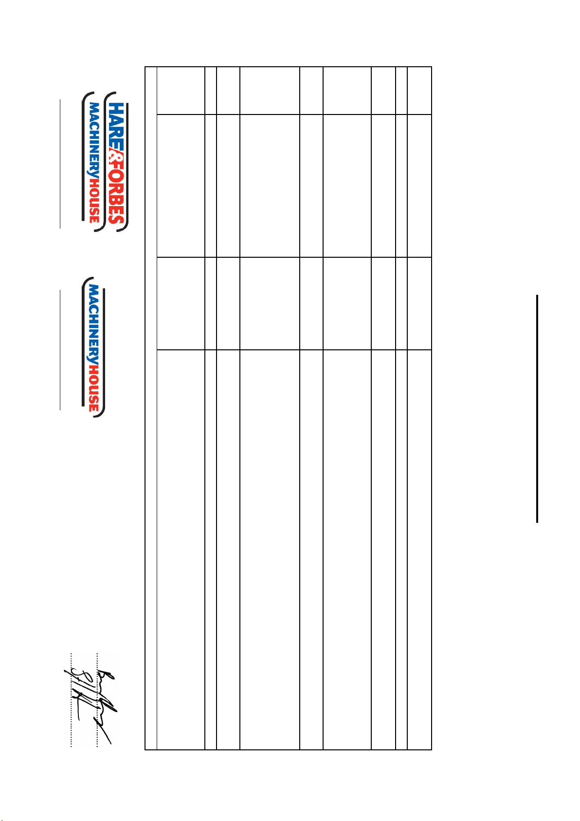
NEW MACHINERY HAZARD IDENTIFICATION, ASSESSMENT & CONTROL
SHEARING
MEDIUM
Make sure all guard are secured shut when machine is on.
Pipe/Tube Notcher - Electric
H
Item
B
Hazard
Identification
F
Developed in Co-operation Between A.W.I.S.A and Australia Chamber of Manufactures
This program is based upon the Safe Work Australia, Code of Practice - Managing Risks of Plant in the Workplace ( WHSA 2011 No10 )
Safety officer:
O
MEDIUM
D
Risk Control Strategies
(Recommended for Purchase / Buyer / User)
Secure & support work material on Notcher.
Eliminate, avoid loose clothing / Long hair etc.
Assessment
PLANT SAFETY PROGRAM
No.
Do not place hands or fingers inside moving parts of notcher.
Stand clear of moving parts on machine.
Ensure work material and cutter are securerly fastened before use.
Use machine on solid level working surface.
A
HIGH
Do not place hands or fingers inside moving parts of notcher.
ENTANGLEMENT
LOW
Do not adjust or clean machine until the machine has fully stopped.
Make sure all guard are secured shut when machine is on.
MEDIUM
LOW
Wear appropriate clothing to prevent hot swarf.
STRIKING
Wear safety glasses.
Remove all loose objects around moving parts.
Revised Date:
Authorised and signed by:
www.machineryhouse.com.au
www.machineryhouse.co.nz
25th January 2019
Wear hearing protection as required.
OTHER HAZARDS, NOISE
Manager:
 Loading...