


BMMTRS1

BMMTRS1
Original Instructions
SNA Europe SAS
BP 20104 Eragny
F-95613 Cergy Pontoise- France

ENGLISH
Contents
BMMTRS1
1. GENERAL INSTRUCTIONS ................................ 3
1.1 Precaution safety measures
1.1.1 Preliminary
1.1.2 During use ............................................................. 3
1.2 Symbols ............................................................... 4
1.3 Instructions ......................................................... 5
2. DESCRIPTION ..................................................... 5
2.1 Instrument Familiarization ................................. 5
2.2 LCD Display ......................................................... 6
2.3 Key pad ................................................................ 7
3. FUNCTION DESCRIPTION .................................. 7
3.1 General Functions .............................................. 7
3.1.1 DATA HOLD mode ................................................ 7
3.1.2 Manual ranging and Auto-range mode .................. 8
3.1.3 Battery saver ......................................................... 8
3.1.4 Relative measurement mode ................................ 8
3.1.5 True RMS measurement ....................................... 8
3.2 Measurement Functions ..................................... 8
3.2.1 AC and DC Voltage measurement ........................ 8
3.2.2 Resistance measurement ..................................... 9
3.2.3 Capacitance measurement ................................... 10
3.2.4 Continuity Check ................................................... 11
3.2.5 Diode Test ............................................................. 12
3.2.6 Frequency measurement ...................................... 13
3.2.7 Temperature measurement ................................... 13
3.2.8 Current measurement ........................................... 14
3.2.9 NCVhEF ................................................................ 15
3.2.10 PC Link ................................................................. 15
4. TECHNICAL SPECIFICATIONS .......................... 15
4.1 General specications ........................................ 15
4.2 Measurement specications .............................. 16
4.2.1 Voltage .................................................................. 16
4.2.2 Frequency ............................................................. 17
4.2.3 Resistance ............................................................ 17
4.2.4 Diode Test ............................................................. 17
4.2.5 Continuity Check ................................................... 18
4.2.6 Capacitance .......................................................... 18
4.2.7 Temperature .......................................................... 18
4.2.8 Current .................................................................. 18
............................................................ 3
.............................. 3
5. MAINTENANCE ................................................... 19
5.1 General maintenance .......................................... 19
5.2 Fuse replacement ............................................... 20
5.3 Battery replacement ........................................... 20
6. ACCESSORIES
.................................................... 20
2

BMMTRS1
ENGLISH
1. GENERAL INSTRUCTIONS
This instrument complies with IEC 61010-1: 2001, CAT III 1000V and CAT IV 600V overvoltage standards.
See Specications.
To get the best service from this instrument, read carefully this user’s manual and respect the detaile
safety precautions.
International symbols used on the Meter and in this manual are explained in chapter 1.2.
1.1 Precautions safety measures
1.1.1 Preliminary
• As the possibilities of high transient overvoltage occurred in today’s power systems increase, more
stringent safety standards are set for the electrical test equipment. Transients on electrical systems
(power grid, feeder or branch circuits) will trigger a series of incidents that may result in serious
personal injury. To protect you against transients, safety must be built into the test equipment.
Overvoltage
category
CAT I
CAT II
In brief Examples
Electronic • Protected electronic equipment.
Single-phase
receptacle connected loads
• Equipment connected to (source) circuits in which measures are taken to
limit transient overvoltage to an appropriately low level.
• Any high-voltage, low-energy source derived from a high winding resist-
ance transformer, such as the high-voltage section of a copier.
• Appliance, portable tools, and other household and similar loads.
• Outlet and long branch circuits.
• Outlets at more than 10 meters (30 feet) from CAT III source.
• Outlets at more that 20 meters (60 feet) from CAT IV source.
CAT III
CAT IV
Three-phase distribution, including
single-phase commercial lighting
Three-phase at
utility connection, any outdoor
conductors
• Equipment in xed installations, such as switchgear and polyphase motors.
• Bus and feeder in industrial plants.
• Feeders and short branch circuits, distribution panel devices.
• Lighting systems in larger buildings.
• Appliance outlets with short connections to service entrance.
• Refers to the “origin of installation”; i.e., where low-voltage connection is
made to utility power.
• Electricity meters, primary overcurrent protection equipment.
• Outside and service entrance, service drop from pole to building, run
between meter and panel.
• Overhead line to detached building, underground line to well pump.
• When using this Multimeter, the user must observe all normal safety rules concerning:
— Protection against the dangers of electric current.
— Protection of the Multimeter against misuse.
• For your own safety, only use the test probes supplied with the instrument. Before use, check that
they are in good condition.
1.1.2 During use
• If the meter is used near noise generating equipment, be aware that display may become unstable
or indicate large errors.
• Do not use the meter or test leads if th ey look damaged.
• Use the meter only as specied in this manual; otherwise, the protection provided by the meter may
be impaired.
• Use extreme caution when working around bare conductors or bus bars.
3

BMMTRS1
ENGLISH
• Do not operate the meter around explosive gas, vapor, or dust.
• Verify a Meter’s operation by measuring a known voltage. Do not use the Meter if it operates abnormally. Protection may be impaired. When in doubt, have the Meter serviced.
• Uses the proper terminals, function, and range for your measurements.
• When the range of the value to be measured is unknown, check that the range initially set on the
multimeter is the highest possible or, wherever possible, choose the auto-ranging mode.
• To avoid damages to the instrument, do not exceed the maximum limits of the input values shown
in the technical specication tables.
• When the multimeter is linked to measurement circuits, do not touch unused terminals.
• Caution when working with voltages above 60Vdc or 30Vac rms. Such voltages pose a shock
hazard.
• When using the probes, keep your ngers behind the nger guards.
• When making connections, connect the common test lead before connecting the live test lead; when
disconnecting, disconnect the live test lead before disconnecting the common test lead.
• Before changing functions, disconnect the test leads from the circuit under test.
• For all dc functions, including manual or auto-ranging, to avoid the risk of shock due to possible
improper reading, verify the presence of any ac voltages by rst using the ac function. Then select
a dc voltage range equal to or greater than the ac range.
• Disconnect circuits power and discharge all high-voltage capacitors before testing resistance, continuity, diodes, or capacitance.
• Never perform resistance or continuity measurements on live circuits.
• Before measuring current, check the meter’s fuse and turn off power to the circuit before connecting
the meter to the circuit.
• In TV repair work, or when carrying out measurements on power switching circuits, remember that
high amplitude voltage pulses at the test points can damage the multimeter. Use of a TV lter will
attenuate any such pulses.
• Use just one 6F22 battery, properly installed in the Meter’s battery case, to power the Meter.
• Replace the battery as soon as the battery indicator ( ) appears. With a low battery, the Meter
might produce false readings that can lead to electric shock and personal injury.
• Do not measure voltages above 1000V in Category III, or 600V in Category III installations.
• When in REL mode, the “REL” symbol is displayed. Caution must be used because hazardous
voltage may be present.
• Do not operate the Meter with the case (or part of the case) removed.
4
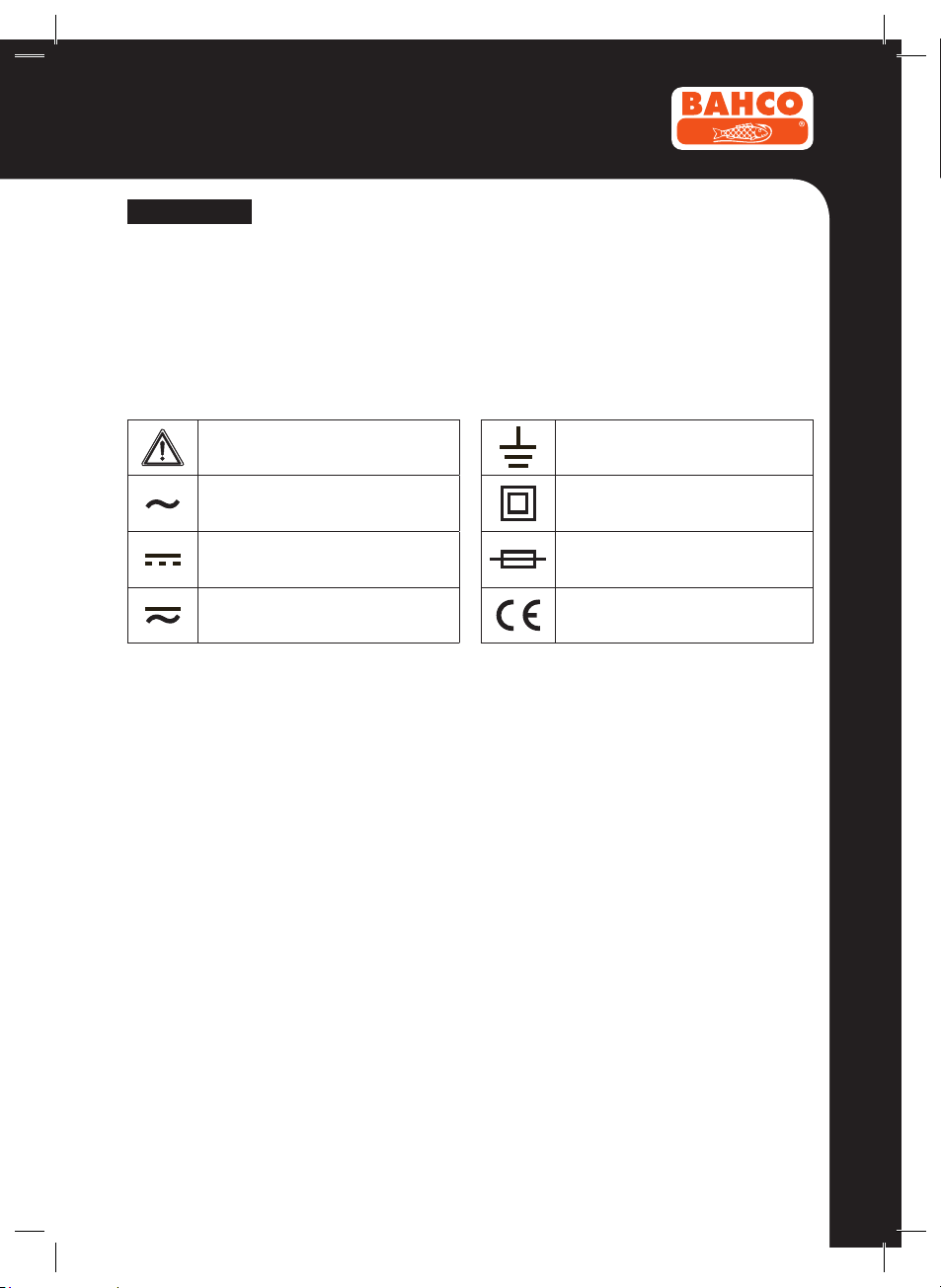
1.2 Symbols
Symbols used in this manual and on the instrument:
CAUTION: refer to the instruction manual.
Incorrect use may result in damage to the
device or its components.
AC (Alternating Current)
DC (Direct Current)
AC or DC
Earth ground
Double insulated
Fuse
Conforms to European Union directives
BMMTRS1
ENGLISH
1.3 Instructions
• Remove test leads from the Meter before opening the Meter case or battery cover.
• When servicing the Meter, use only specied replacement parts.
• Before opening up the instrument, always disconnect from all sources of electric current and make
sure you are not charged with static electricity, which may destroy internal components.
• Any adjustment, maintenance or repair work carried out on the meter while it is live should be carried out only by appropriately qualied personnel, after having taken into account the instructions in
this present manual.
• A “qualied person” is someone who is familiar with the installation, construction and operation of
the equipment and the hazards involved. He is trained and authorized to energize and de-energize
circuits and equipment in accordance with established practices.
• When the instrument is opened up, remember that some internal capacitors can retain a dangerous
potential even after the instrument is switched off.
• If any faults or abnormalities are observed, take the instrument out of service and ensure that it
cannot be used until it has been checked out.
• If the meter is not going to be used for a long time, take out the battery and do not store the meter
in high temperature or high humidity environment.
2. DESCRIPTION
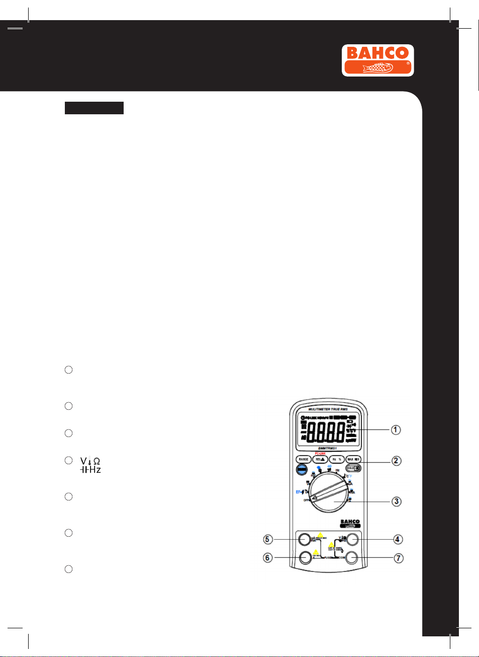
2.1 Instrument Familiarization
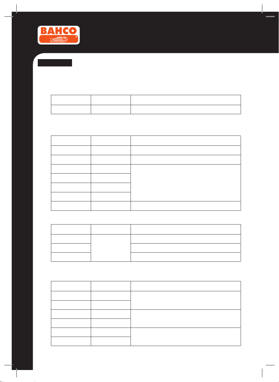
The front panel is shown as in Figure 2-1, explanation being as follows:
1
LCD display
Used for displaying the measuring results and
various symbols.
2
Keypad
Measurement function keys.
3
Rotary switch
Used for selecting measurement functions.
4
Terminal receiving the red test lead for
5
µA/mA
Terminal receiving the red test lead for µA, mA
6
A
Terminal receiving the red test lead for 6A, 10A
7
COM
Terminal receiving the black test lead as a common
voltage, resistance, capacitance, frequency,
temperature, diode and continuity measurements.
measurements.
measurements.
reference.
Figure 2-1
5
BMMTRS1
ENGLISH
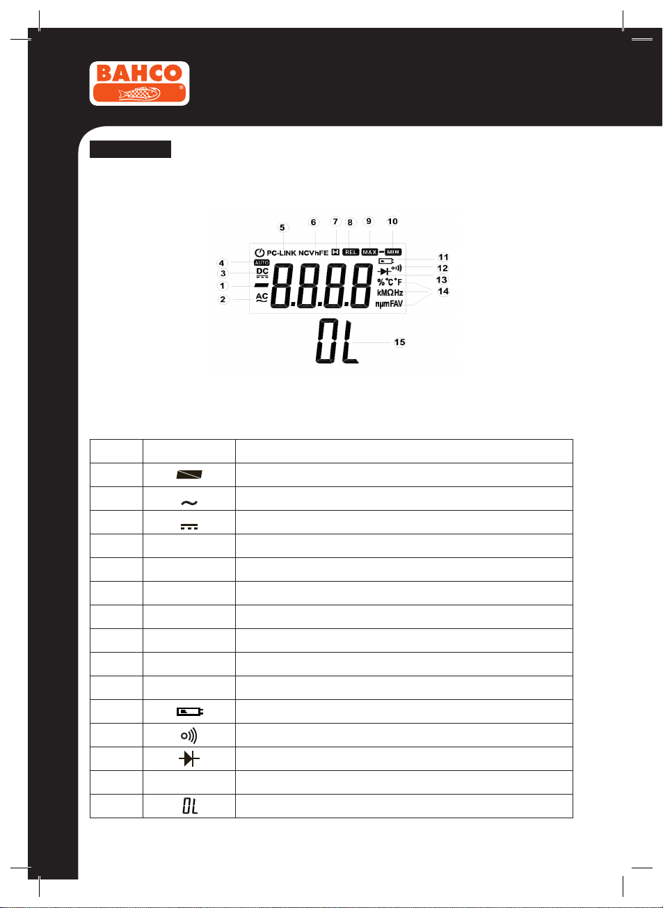
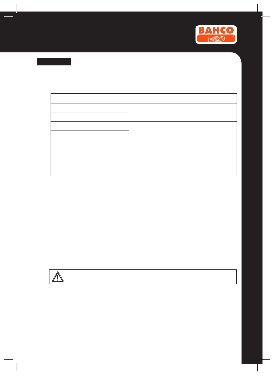
2.2 LCD Display
Figure 2-2
LCD screen is shown as in Figure 2-2, with its every symbol’s meaning shown as in the Table 1:
No. Symbol Meaning
1 Indicates negative readings
2
3
AC
DC
Indicator for AC voltage or current
Indicator for DC voltage or current
4
5
6
7
8
9
10
11 Low battery indication
12 The meter is in Continuity Check mode
13 The meter is in Diode Test mode
14
15 This symbol means that the input is too large for the selected range
AUTO
PC-LINK
NCV
H
REL
MAX
MIN
%CºFº KMΩHz
nµm FAV
The meter is in the Auto-range mode in which the meter automatically selects
The Meter is in the data transmission mode
No contact AC Voltage detect
The meter is in Data Hold mode w
The meter is in Relative Measurement mode
Display maximum data
Display minimum data
Measurement units
6

BMMTRS1
ENGLISH
2.3 Keypad
2.3.1 SELECT
Change to the second function.
1. At Ω and
Switches between Resistance measurement, Diode Test and Continuity check.
2. At A mA µA position
Switches between DC and AC current.
3. Power-up Option
Disables automatic power-off feature. Keep press this key when power on.
HOLD
2.3.2
Press it to enter and exit the Data Hold mode. Press it and hold 2 seconds, backlight on; if press it
and hold for 2 seconds again, backlight off.
2.3.3 RANGE
At V~, V , A, mA and µA.
1. Press RANGE to enter in manual ranging mode.
2. Press RANGE to step through the ranges available for the selected function.
3. Press and hold RANGE for 2 seconds to return to auto-ranging.
2.3.4 REL r
1. Press REL r to enter and exit the Relative measurement mode. (Except Hz/Duty)
2. Keep press REL r more than 2 seconds to enter the PCLINK mode.
2.3.5 Hz %
At V~, A, mA and µA.
1. Press it to start the frequency counter.
2. Press it again to enter duty (load factor) mode.
3. Press it again to exit the frequency counter mode.
2.3.6 MAX/MIN
This key is for measuring maximum value and minimum value.
1. Press it to enter Max/Min mode.
2. Press it again; the LCD will display the Maximum Value.
3. Press it again; the LCD will display the Minimum Value.
4. Press and hold it for two seconds, the meter will return to normal measurement state.
(Except Hz/Duty and Capacitance)
position
3. FUNCTION DESCRIPTION
3.1 General Functions
3.1.1 DATA HOLD mode
Data Hold mode makes the meter stop updating the display. Enabling Data Hold function in auto-
range mode makes the meter switch to Manual ranging mode, but the full-scale range remains the
same. Data Hold function can be cancelled by changing the measurement mode, pressing RANGE
key, or push
HOLD
key again.
7
ENGLISH
BMMTRS1
To enter and exit the Data Hold mode:
1. Press
HOLD
key (short press). Fixes the display on the current value, H is displayed.
2. A second short press returns the meter to normal mode.
3.1.2 Manual ranging and Auto-range mode
The Meter has both manual ranging and auto-range options.
• In the auto-range mode, the Meter selects the best range for the input detected. This allows you to
switch test points without having to reset the range.
• In the manual ranging mode, you select the range. This allows you to override auto-range and lock
the meter in a specic range.
• The Meter defaults to the auto-range mode in measurement functions that have more than one
range. When the Meter is in the auto-range mode, AUTO is displayed.
To enter and exit the manual range mode:
1. Press RANGE key. The Meter enters the manual ranging mode. AUTO turns off. Each presses
of RANGE key increments the range. When the highest range is reached, the Meter wraps to the
lowest range.
NOTE: If you manually change the measurement range after entering the Data Hold modes, the
Meter exits this mode.
2. To exit the manual ranging mode, press and hold down RANGE key for two seconds. The Meter
returns to the auto-range mode and AUTO is displayed.
3.1.3 Battery Saver
The Meter enters the “sleep mode” and blanks the display if the Meter is on but not used for 15
minutes.
Press the
HOLD
key or rotate the rotary switch to wake the meter up.
To disable the Sleep mode, hold down the SELECT key while turning the meter on.
3.1.4 Relative measurement mode
The Meter will display relative measurement in all functions except frequency.
To enter and exit the relative measurement mode:
1. With the Meter in the desired function, touch the test leads to the circuit on which you want future
measurement to be based.
2. Press REL r key to store the measured value and activate the relative measurement mode. The
difference between the reference value and subsequent reading is displayed.
3. Press REL r key again return the Meter to normal operation.
3.1.5 TRUE RMS measurement
All the AC measurement values are TRUE RMS (true root-mean-square) values.
Frequency range is up to 1KHz.
3.2 Measurement Functions
3.2.1 AC and DC Voltage measurement
To avoid electrical shock and/or damage to the instrument, do not attempt to take
any voltage measurement that might exceeds 1000Vdc or 1000Vac rms.
To avoid electrical shock and/or damage to the instrument, do not apply more than
1000Vdc or 1000Vac rms between the common terminal and the earth ground.
8
BMMTRS1
ENGLISH
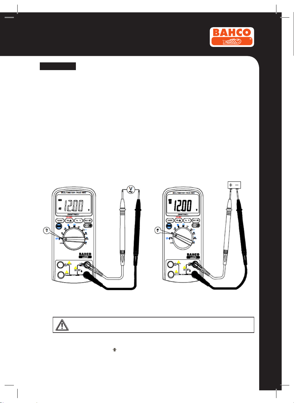
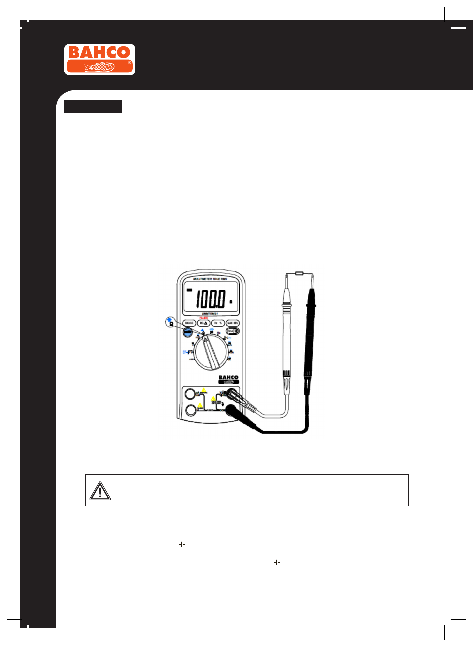
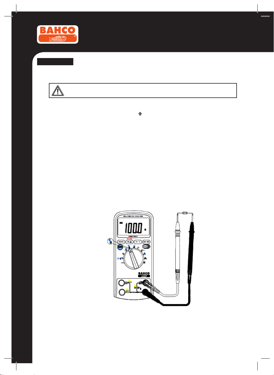
The Meter’s voltage ranges are 600.0mV, 6.000V, 60.00V, 600.0V and 1000V.
To measure ac or dc voltage (set up and connect the Meter as shown in Figure 3-1):
1. Set rotary switch to the DCV, ACV or AC/DC mV range.
2. Connect the black and red test leads to the COM and V terminals respectively.
3. Connect the test leads to the circuit being measured
4. Read the displayed value. The polarity of red test lead connection will be indicated when making
a DCV measurement.
NOTE: Unstable display may occur especially at 600mV range, even though you do not put test
leads into input terminals.
For better accuracy when measuring the DC offset of an ac voltage, measure the AC voltage rst.
Note the AC voltage range, then manually select a DC voltage range equal to or higher than the AC
range. This improves the accuracy of the DC measurement by ensuring that the input protection
circuits are not activated.
AC Voltage DC Voltage
Figure 3-1 Measuring AC and DC Voltage
3.2.2 Resistance measurement
To avoid electrical shock and/or damage to the instrument, disconnect circuit
power and discharge all high-voltage capacitors before measuring resistance.
The Meter’s resistance ranges are 600.0Ω, 6.000kΩ, 60.00kΩ, 600.0kΩ, 6.000MΩ and 60.00MΩ.
To measure resistance (set up the Meter as shown in gure 3-2):
1. Set the rotary switch to Ω range.
2. Connect the black and red test leads to the COM and VΩ terminals respectively.
3. Connect the test leads to the circuit being measured and read the displayed value.
9
BMMTRS1
ENGLISH
Some tips for measuring resistance:
• The measured value of a resistor in a circuit is often different from the resistor’s rated value. This is
because the Meter’s test current ows through all possible paths between the probe tips.
• In order to ensure the best accuracy in measurement of low resistance, short the test leads before
measurement and memory the test probe resistance in mind. This necessary to subtract for the
resistance of the test leads.
• The resistance function can produce enough voltage to forward-bias silicon diode or transistor junctions, causing them to conduct. To avoid this, do not use the 60MΩ range for in-circuit resistance
measurements.
• On 60MΩ range, the meter may take a few seconds to stabilize reading. This is normal for high
resistance measuring.
• When the input is not connected, i.e. at open circuit, the gure “OL” will be displayed for the over-
range condition.
3.2.3 Capacitance measurement
The Meter’s capacitance ranges are 6.000nF, 60.00nF, 600.0nF, 6.000µF, 60.00µF, 600.0µF,
6.000mF, 60.00mF.
To measure capacitance (set up the Meter as shown in Figure 3-3):
1. Set the rotary switch to Ω range.
2. Press the SELECT key to select capacitance Test
3. Connect the black and red test leads to the COM and terminals respectively (or you can use
capacitor test lead).
4. Connect the test leads to the capacitor being measured and read the displayed value.
10
Figure 3-2 Measuring Resistance
To avoid electrical shock and/or damage to the instrument, disconnect circuit
power and discharge all high-voltage capacitors before measuring capacitance.
Use the dc voltage function to conrm that the capacitor is discharged.

BMMTRS1
ENGLISH
Some tips for measuring capacitance:
• The meter may take a few seconds (>30 seconds in 600.0µF range) to stabilize reading. This is
normal for high capacitance measuring.
• To improve the accuracy of measurements less than 6nF, subtract the residual capacitance of the
Meter and leads.
• Below 100pF, the accuracy of measurements is unspecied.
Figure 3-3
Measuring Capacitance
3.2.4 Continuity Check
To avoid electrical shock and/or damage to the instrument, disconnect circuit
power and discharge all high-voltage capacitors before testing for Continuity.
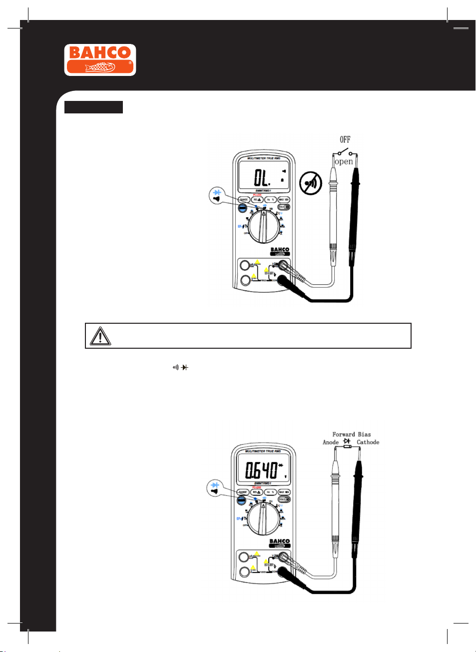
To test for continuity (set up the Meter as shown in Figure 3-4):
1. Set the rotary switch to range.
2. Connect the black and red test leads to the COM and Ω terminals respectively.
3. Connect the test leads to the resistance in the circuit being measured.
4. When the test lead to the circuit is below 50Ω, a continuous beeping will indicate it.
NOTE: Continuity test is available
to check open/short of the circuit.
11
BMMTRS1
ENGLISH
Figure 3-4
Checking the Continuity
3.2.5 Diode Test
To avoid electrical shock and/or damage to the instrument, disconnect circuit
To test a diode out of a circuit (set up the Meter as shown in Figure 3-5):
1. Set the rotary switch to range.
2. Press the SELECT key to select Diode Test.
3. Connect the black and red test leads to the COM and VΩ terminals respectively.
4. For forward-bias readings on any semiconductor component, place the red test lead on the com-
5. The meter will show the approx. forward voltage of the diode.
power and discharge all high-voltage capacitors before testing diodes.
ponent’s anode and place the black test lead on the component’s cathode.
12
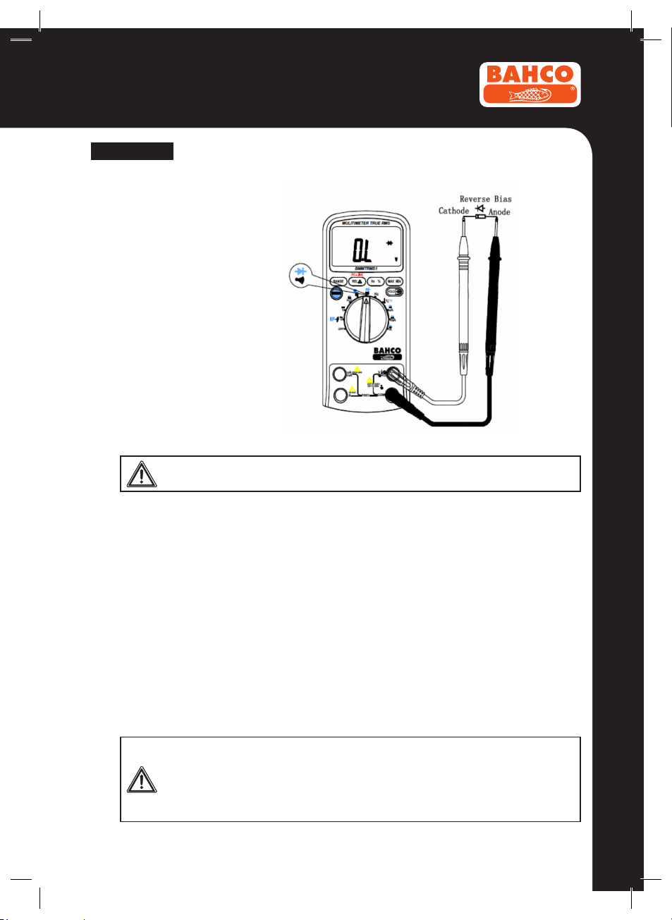
In a circuit, a good diode (Si)
should still produce a forward
bias reading of 0.5V to 0.8V;
however, the reverse-bias reading can vary depending on the
resistance of other pathways
between the probe tips.
BMMTRS1
ENGLISH
Figure 3-5
Measuring Diodes
3.2.6 Frequency and Duty Cycle measurement
Do not measure Frequency on high voltage (>1000V) to avoid electrical shock
hazard and/or damage to the instrument.
The Meter can measure Frequency or Duty Cycle while making either an AC Voltage or AC Current
measurement.
To measure frequency or Duty Cycle:
1. With the meter in the desired function (AC Voltage or AC Current), press the Hz % key.
2. Read the frequency of the AC signal on the display.
3. To make a duty cycle measurement, press the Hz % key again.
4. Read the percent of duty cycle on the display.
5. Set the rotary switch to the Hz range.
6. Insert the black and red test leads into the COM and Hz input terminals.
7. Connect the test leads tip in parallel with the circuit to be measured. And don’t touch any electrical
conductors.
8. At frequency measuring status, press Hz % one time then meter enters duty cycle measuring
status, press it again then return to frequency measuring status.
9. Read the result directly from the display.
NOTE: In noisy environment, it is preferable to use shield cable for measuring small signal
3.2.7 Temperature measurement
To avoid electrical shock and/or damage to the instrument, do not apply more
than 250Vdc or 220Vac rms between the °C terminal and the COM terminal.
To avoid electrical shock, do not use this instrument when voltages at the measurement surface exceed 60v dc or 24v rms. Ac.
To avoid damage or burns. Do not make temperature measurement in microwave
ovens.
13
BMMTRS1
ENGLISH
To measure temperature:
1. Set the rotary switch to °C range and the LCD will show the current environment temperature.
2. Insert ‘K’ type thermocouples into the COM terminal and °C terminal (or you can insert it by
using Multi Function Socket), Taking care to observe the correct polarity.
3. Touch the object with the thermocouple probe for measurement.
4. Read the stable reading from LCD.
3.2.8 Current measurement
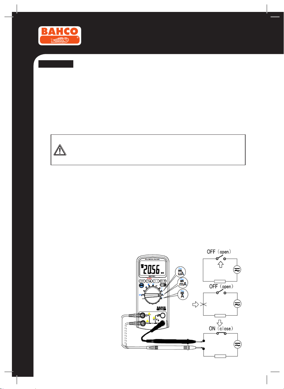
The Meter’s current ranges are 600.0µA, 6000µA, 60.00mA, 600.0mA, 6.000A and 10.00A.
To measure current (set up the Meter as shown in Figure 3-6):
1. Turn off power to the circuit. Discharge all high voltage capacitors.
2. Set the rotary switch to the µA, mA or A range.
3. Press the SELECT key to select DCA or ACA measuring mode.
4. Connect the black test lead to the COM terminal and the red test leads to the mA terminal for a
5. Break the circuit path to be tested.
Touch the black probe to the more negative side of the break; touch the red probe to the more positive
6. Turn on power to the circuit; then read the display. Be sure to note the measurement units at the
7. Turn off power to the circuit and discharge all high voltage capacitors. Remove the Meter and
To avoid damage to the Meter or injury if the fuse blows, never attempt an in-circuit
current measurement where the open-circuit potential to earth is greater than 1000V.
To avoid damage to the meter, check the meter’s fuse before proceeding. Use the proper terminals, function, and range for your measurement. Never place the probes in parallel with a circuit or component when the leads are plugged into the current terminals.
maximum of 600mA. For a maximum of 10A, move the red test lead to the A terminal.
side of the break. (Reversing the leads will give a negative reading, but will not damage the Meter.)
right side of the display (µA, mA or A). When only the gure “OL” displayed, it indicates over range
situation and the higher range has to be selected.
restore the circuit to normal operation.
Figure 3-6
Measuring Current
14

BMMTRS1
ENGLISH
3.2.9 NCV (Non-Contact Voltage detect)
Set rotary switch to the ACV / EF- range, Press the SELECT key to go NCV detect mode. Put
the EF-DETECT AREA close to the AC power cable or the power socket, if AC electrical voltage is
present, the Buzzer warning will sound, and the symbol bar “-“ will be displayed on the LCD.
The lowest detect voltage is around 50V 50/60Hz.
The LCD display EF, when detect the AC voltage signal, the LCD display ‘ - ’/‘ -- ’/‘ --- ’/‘ ---- ’ from
weak to strong.
This function is depending model.
3.2.10 PC Link
The meter has serial data output function. It can be connected with PC by USB interface, so the
measured data can be recorded, analyzed, processed and printed by PC. Before use this function,
you need install the PC-Link software and USB driver in your PC.
Keep press REL r more than 2 seconds and the meter enter PC-Link mode, the symbol “PC-
LINK” will appear on LCD, and the serial data output function is active.
Auto power off function is disabled when PCLINK function active.
PC-LINK SOFT OPERATING MANUAL
1. Make sure the two Install USB driver and Install software/RUN les in the attached USB stick
successfully installed before any measurement.
2. Connect the meter’s OPTICAL PORT and computer USB port with the USB cable.
3. Run the PC-LINK software, click the Start button.
4. Keep press REL r key more than 2 seconds on the meter, the symbol “PC-LINK” will appear on
the LCD if the serial data output function is active.
As for check the USB cable success recognized, we can view it in the Device Manager by following
these steps:
• Right-click the My Computer icon on the Windows desktop, and then click Properties.
• Click the Hardware tab and then click Device Manager.
• Scroll through the list of installed devices till you locate the Ports (Com and LPT) entry. Click the
plus (+) beside this entry to view the installed ports, If no errors occur, the USB to Serial COM
Port (COM x) will appear, COM x is just the proper port, here x is a specic number.
5. Now the PC-LINK SOFT view the synchronic data or graph in the software interface.
6. To disable the PCLINK function, Keep press REL r key more than 2 seconds.
4. TECHNICAL SPECIFICATIONS
4.1 General specications
Environment conditions:
1000V CAT III and 600V CAT IV
Pollution degree: 2
Altitude < 2000 m
Operating temperature: 0~40°C, 32°F~122°F(<80% RH, <10°C non-condensing)
Storage temperature: -10~60°C, 14°F~140°F(<70% RH, battery removed)
Temperature Coefcient: 0.1x(specied accuracy) / °C (<18°C or >28°C)
MAX. Voltage between terminals and earth ground: 1000V AC rms or 1000V DC.
Fuse Protection: µA and mA: F 0.63A/1000V Ø 10.3x38; A: F 10A/1000V Ø 10.3x38.
Sample Rate: 3 times/sec for digital data.
Display: 3 5/6 digits LCD display. Automatic indication of functions and symbols.
15

BMMTRS1
ENGLISH
Range selection: automatic and manual.
Over Range indication: LCD will display “OL”.
Low battery indication: The “ ” is displayed when the battery is under the proper operation
range.
Polarity indication: “ ” displayed automatically.
Power source: 9V
Battery type: 6F22.
Dimensions: 190(L)x90(W)x40(H) mm.
Weight: 500 g. Approx. (battery included).
4.2 Measurement specications
Accuracy is specied for one year after calibration, at operating temperatures of 18°C to 28°C, with
relative humidity at less than 80%.
Accuracy specications take the form of: ± (% of Reading + Number of Least Signicant Digits)
4.2.1 Voltage
DCV
Range Resolution Accuracy
600mV 0.1mV ±(0.5% of rdg +5 digits)
6V 1mV
60V
600V 100mV
1000V
10mV
1V
±(0.8% of rdg +5 digits)
±(1.0% of rdg +2 digits)
16
ACV
Range Resolution Accuracy
600mV 0.1mV
6V 1mV
60V 10mV
600V 100mV
750V 1V ±(1.5% of rdg + 5 digits)
Above accuracies can be guaranteed within 5%~100% of the full range.
The RMS meter has residual value within 10 counts when the test leads are shorten, but that will
not affect the accuracy of measurement.
1. Frequency Range for ACV: 40Hz~400Hz.
2. Response for ACV: RMS measure, calibrated in rms of sine wave.
3. Overload Protection: 1000V dc or 1000V ac rms.
4. Input Impedance (Nominal): DC voltage: >10MΩ; AC voltage: >10MΩ
±(1.0% of rdg + 5 digits)

BMMTRS1
ENGLISH
4.2.2 Frequency
Logic frequency (1Hz-1MHz)
Range Resolution Accuracy
99.99Hz 0.01 Hz
999.9Hz 0.1 Hz
9.999kHz 0.001kHz
99.99kHz 0.01kHz
999.9kHz
0.1kHz
Linear frequency (6HZ~10KHZ)
Range Resolution Accuracy
99.99Hz 0.01 Hz
9.999kHz 0.001kHz
Above accuracies can be guaranteed within 10%~100% of the full range.
±(0.1% of rdg+3digits)
±(0.05% of rdg+8digits)999.9Hz 0.1 Hz
4.2.3 Resistance
Range Resolution Accuracy
600.0Ω 0.1Ω ±(0.5% of rdg+3 digits)
6.000kΩ 1Ω
60.00kΩ 10Ω
600.0kΩ 100Ω
6.000MΩ 1kΩ
60.00MΩ 10kΩ ±(1.5% of rdg+5 digits)
4.2.4 Diode Test
Range Resolution Test Condition
1 V 0.001V
±(0.5% of rdg+2 digits)
Forward DC current approximately 1mA.
Reversed DC voltage approximately 1.5V.
17
ENGLISH
4.2.5 Continuity Check
Range Resolution Test Condition
600Ω 0.1Ω Open circuit voltage: approx. 0.5V
Description: Continuity beeper ≤50Ω
4.2.6 Capacitance
Range Resolution Accuracy
6nF 1pF ±(5.0% of rdg +20 digits)
60nF 10pF ±(3.0% of rdg +20 digits)
600nF 100pF
6µF 1nF
60µF
600µF 100nF
6mF 1µF ±(5.0% of rdg +20 digits)
10nF
BMMTRS1
± (5.0% of rdg+10 digits)
4.2.7 Temperature
Range Resolution Accuracy
-200~0°C
0~400°C ±(2.0% of rdg+ 3°C)
400~1200°C ±(2.0% of rdg+ 2°C)
1°C
±(5.0% of rdg + 4°C)
Note: The specications of temperature don’t include thermocouple errors.
4.2.8 Current
Range Resolution Accuracy
600µA 0.1µA
6000µA 1µA
60mA 0.01mA
600mA 0.1mA
6A 1mA
10A 10mA
±(1.5% of rdg+3 digits)
±(1.5% of rdg+3 digits)
±(1.5% of rdg+5 digits)
18
BMMTRS1
ENGLISH
ACA
Range Resolution Accuracy
600µA 0.1µA
6000µA 1µA
60mA 0.01mA
600mA
6A 1mA
10A 10mA
Above accuracies can be guaranteed within 5%~100% of the full range.
The true RMS meter has residual value within 10 counts when the test leads are shorten, but that
will not affect the accuracy of measurement.
1. Frequency Range for ACA: 40Hz-400Hz
2. Overload protection: F 10A/1000V fuse for 10A
Overload protection: F 0.63A/1000V fuse for µA and mA ranges.
3. Maximum input current: 600mA DC or 600mA AC rms for µA and mA ranges, 10A DC or 10A AC
rms for 10A ranges.
4. For measurements>6A, 15 seconds ON each 10 minutes; Above 10A unspecied.
0.1mA
±(1.8% of rdg+5 digits)
±(1.8% of rdg+5 digits)
±(3.0% of rdg+8 digits)
5. MAINTENANCE
This section provides basic maintenance information, including fuse and battery replacement
instructions.
Do not attempt to repair or service your Meter unless you are qualied to do so and have the
relevant calibration, performance test, and service information.
5.1 General Maintenance
To avoid electrical shock or damage to the meter, do not get water inside the case.
Remove the test leads and any input signals before opening the case.
Periodically wipe the case with a damp cloth and mild detergent. Do not use abrasives or solvents.
Dirt or moisture in the terminals can affect readings.
To clean the terminals:
Turn the meter off and remove all test leads.
Shake out any dirt that may be in the terminals.
Soak a new swab with a cleaning and oiling agent (such as WD-40).
Work the swab around in each terminal. The oiling agent insulates the terminals from moisture-
related contamination.
19

ENGLISH
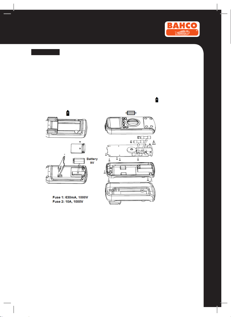
5.2 Fuse replacement
Before replacing the fuse, disconnect test leads and/or any connectors from any circuit
under test. To prevent damage or injury replace the fuse only with specied ratings.
1. Set rotary switch to the OFF position.
2. Disconnect test leads and/or any connectors from the terminals.
3. Use a screwdriver to unlock the four screws on the rear cover.
4. Take out the rear cover from the meter.
5. Remove the fuse by gently prying one end loose, then sliding the fuse out of its bracket.
6. Install the replacement fuses only with specied ratings: F 0.63A/1000V Ø10.3x38 and
F 10A/1000V Ø10.3x38
7. Rejoin the rear cover and tighten the screws.
5.3 Battery replacement
To avoid false readings, which could lead to possible electric shock or personal
injury, replace the battery as soon as the battery indicator ( ) appears.
Before replacing the battery, disconnect test leads and/or any connectors from
any circuit under test, turn the meter off and remove test leads from the input
terminals.
1. Set rotary switch to the OFF position.
2. Disconnect test leads and/or any connectors from the terminals.
3. Use a screwdriver to unlock the two screws on the battery cover.
4. Take out the battery cover from the meter.
5. Remove the used battery.
6. Replace with one new 9V battery (6F22).
7. Rejoin the battery cover and tighten the screws.
BMMTRS1
6. ACCESSORIES
20
Delivered with the multimeter:
User's manual One piece
Test leads with clamp 10A One piece
Test leads with needle 10A One piece
"K" type Thermocouple leads One piece
USB cable One piece
PC-Link software + user manual USB stick One piece
BMMTRS1
ENGLISH
REPLACING THE BATTERY AND FUSES
WARNING
To avoid shock, injury or damage the meter: Use only fuses with the aperage, interrupt,
voltage and speed ratings specied.
Replace the battery as soon as the low battery indicator appears
21

FRANÇAIS
Sommaire
BMMTRS1
1. INSTRUCTIONS GENERALES .......................... 23
1.1 Mesures de sécurité .......................................... 23
1.1.1 Préliminaire .......................................................... 23
1.1.2 En cours d’utilisation ............................................ 24
1.2 Symboles ............................................................ 25
1.3 Instructions ........................................................ 25
2. DESCRIPTION .................................................... 25
2.1 Familiarisation avec l’instrument ..................... 25
2.2 Afchage LCD .................................................... 26
2.3 Clavier de commande ........................................ 27
3. DESCRIPTION DES FONCTIONS ...................... 28
3.1 Fonctions générales .......................................... 28
3.1.1 Mode MAINTIEN DES DONNEES ....................... 28
3.1.2 Mode gamme manuelle et gamme-auto .............. 28
3.1.3 Economiseur de batterier ..................................... 28
3.1.4 Mode mesure relative .......................................... 29
3.1.5 Mesure valeurs efcaces vraies ........................... 29
3.2 Fonctions de mesure ......................................... 29
3.2.1 Mesure Tension AC et DC .................................... 29
3.2.2 Mesure de la résistance ....................................... 30
3.2.3 Mesure de la capacité .......................................... 31
3.2.4 Contrôle de continuité .......................................... 31
3.2.5 Test diode ............................................................. 32
3.2.6 Mesure de la fréquence ....................................... 33
3.2.7 Mesure de la température .................................... 34
3.2.8 Mesure du courant ............................................... 34
3.2.9 NCVhEF ............................................................... 35
3.2.10 PC-Link (Connexion PC) ...................................... 35
22
4. CARACTERISTIQUES TECHNIQUES ............... 36
4.1 Caractéristiques générales ............................... 36
4.2 Caractéristiques des Mesures .......................... 36
4.2.1 Tension ................................................................. 37
4.2.2 Fréquence ............................................................ 37
4.2.3 Résistance ........................................................... 38
4.2.4 Test diode ............................................................. 38
4.2.5 Contrôle continuité ............................................... 38
4.2.6 Capacité ............................................................... 38
4.2.7 Température ......................................................... 39
4.2.8 Courant ................................................................ 39
5. ENTRETIEN ......................................................... 40
5.1 Entretien général ................................................ 40
5.2 Remplacement fusible ....................................... 40
5.3 Remplacement batterie ..................................... 40
6. ACCESSOIRES ................................................... 41

BMMTRS1
FRANÇAIS
1. INSTRUCTIONS GENERALES
Cet instrument est conforme aux normes de surtension IEC 61010-1 : 2001, CAT III 1000V et CAT IV 600V. Voir
les caractéristiques techniques.
Pour une utilisation optimale de cet instrument, veuillez lire attentivement le manuel d’utilisation et respecter les
précautions d’emploi qui y sont détaillées.
Les symboles internationaux utilisés sur ce Multimètre et dans ce manuel sont expliqués au chapitre 1.2.
1.1 Mesures de sécurité
1.1.1 Préliminaire
• Etant donné les possibilités accrues de surtension transitoire élevée sur les systèmes électriques d’au-
jourd’hui, des normes de sécurité plus strictes sont désormais mises en place sur les équipements de
contrôle électriques. Les régimes transitoires sur les systèmes électriques (réseau électrique, circuit primaire ou circuit dérivé) déclencheront une série d’incidents qui peuvent provoquer des blessures cor-
porelles très sérieuses. An de vous protéger contre ces régimes transitoires, des mesures de sécurité
doivent être intégrées dans les équipements de contrôle.
Catégorie de
surtension
CAT I
CAT II
CAT III
CAT IV
En bref Exemples
Electronique • Equipement électronique protégé.
Charges
branchées avec
che femelle
monophasée
Distribution
triphasée, y
compris l’éclairage monophasé
dans les commerces
Triphasé à des
câbles de réseau
de distribution,
conducteur
extérieur
• Equipement branché à des circuits (source) sur lesquels des mesures
sont prises pour limiter à un faible niveau et de façon appropriée des
surtensions transitoires.
• Toute source de haute tension et faible énergie dérivée d’un transformateur à résistance d’enroulement élevée, telle que la partie haute tension
d’un photocopieur.
• Appareil électroménager, outils portatifs et autres charges similaires.
• Prise et circuits dérivés longs.
• Prises à plus de 10 mètres (30 pieds) de la source CAT III.
• Prises à plus de 20 mètres (60 pieds) de la source CAT IV.
• Equipement sur installations xes tels que les mécanismes de commuta-
tion et moteurs polyphasés.
• Barre et circuit primaire dans les installations industrielles.
• Circuits primaires et circuits déviés courts, dispositifs de tableau de
distribution.
• Système d’éclairage dans les grands bâtiments.
• Prises d’appareils avec des couplages courts à l’entrée des branche-
ments.
• Se réfère à “l’origine de l’installation” ; ex., lorsqu’une connexion basse
tension est faite au réseau électrique.
• Compteurs électriques, équipements de protection électrique contre les
surintensités primaires.
• Extérieur et entrée de branchement, cache-entrée du pôle au bâtiment,
course entre le Multimètre et le tableau.
• Ligne suspendue vers un bâtiment séparé, ligne enterrée vers la pompe
de puits.
23

BMMTRS1
FRANÇAIS
• Lorsqu’il utilise ce Multimètre, l’utilisateur doit observer toutes les règles de sécurité de base concernant :
— La protection contre les dangers liés au courant électrique.
— La protection du Multimètre contre les utilisations inadaptées.
• Pour votre propre sécurité, utilisez uniquement les sondes d’essai fournies avec l’instrument. Avant de les
utiliser, vériez leur bon état.
1.1.2 En cours d’utilisation
• Si le Multimètre est utilisé près d’un équipement générant du bruit, sachez que l’afchage peut devenir
instable ou indiquer des valeurs erronées.
• Ne pas utiliser le Multimètre ou les cordons d’essai s’ils sont endommagés.
• Utilisez le Multimètre en respectant bien les instructions spéciées dans le manuel ; sinon, la protection
installée sur le Multimètre peut être détériorée.
• Soyez extrêmement prudent lorsque vous travaillez à proximité de conducteurs nus ou de barres de distribution.
• Ne pas utiliser le Multimètre à proximité de gaz explosif, vapeur ou poussière.
• Vériez le bon fonctionnement du Multimètre en mesurant une tension connue. Ne pas utiliser le Multi-
mètre s’il montre des défauts de fonctionnement. La protection peut être abîmée. Si vous avez des doutes,
donnez le Multimètre à réparer.
• Utilisez les terminaux, fonctions et gamme de valeurs adaptés à vos mesures.
• Lorsque la gamme de valeurs à mesurer n’est pas connue, vériez que la gamme réglée initialement sur
le multimètre est la plus élevée possible ou, lorsque c’est possible, sélectionnez le mode gamme-auto.
• An de ne pas endommager l’instrument, veillez à ne pas dépasser les limites maximales des valeurs
d’entrée spéciées dans les tableaux des caractéristiques techniques.
• Lorsque le multimètre est relié à des circuits de mesure, ne touchez pas aux terminaux non utilisés.
• Attention lorsque vous travaillez sous des tensions continues supérieures à 60V ou tensions alternatives
à 30V rms (valeurs efcaces). De telles tensions peuvent engendrer un risque de chocs.
• Lorsque vous utilisez les pointes de touche, maintenez vos doigts derrière le protège-doigt.
• Lorsque vous effectuez des branchements, branchez le cordon d’essai commun avant de brancher le cordon d’essai sous tension ; au moment de débrancher, débranchez d’abord le cordon d’essai sous tension
avant de débrancher le cordon d’essai commun.
• Avant de changer de fonctions, débranchez les cordons d’essai du circuit sous test.
• Pour toutes les fonctions dc, qu’elles soient manuelles ou en mode gamme-auto, et an d’éviter le risque
de choc lié à une lecture incorrecte, vériez la présence de tensions ac en utilisant d’abord la fonction ac.
Puis sélectionnez une gamme de tension dc égale ou supérieure à la gamme de tension ac.
• Coupez l’alimentation électrique des circuits et déchargez tous les condensateurs haute tension avant de
tester la résistance, la continuité, les diodes ou la capacité.
• Ne jamais mesurer la résistance ou la continuité sur des circuits sous tension.
• Avant de mesurer le courant, vériez le fusible du Multimètre et coupez l’alimentation électrique du circuit
avant de brancher le Multimètre au circuit.
• Pour la réparation de téléviseurs ou lorsque vous mesurez des circuits de commutation électrique, ne pas
oublier que des impulsions de tension à forte amplitude aux points de contrôle peuvent endommager le
multimètre. L’utilisation d’un ltre TV atténuera de telles impulsions.
• N’utilisez qu’une batterie 6F22 correctement installée dans le boitier du Multimètre pour l’alimenter.
• Remplacez la batterie dès que l’indicateur ( ) apparaît. Lorque la batterie est faible, le Multimètre
peut faire apparaître des lectures erronées qui peuvent provoquer des chocs électriques et des blessures
corporelles.
24
BMMTRS1
FRANÇAIS
• Ne pas mesurer d’installations sous tensions supérieures à 1000V en Catégorie III ou supérieures à 600V
en Catégorie III.
• Lorsque vous êtes en mode REL, le symbole “REL” s’afche. Il faut alors faire très attention car la tension
présente peut être dangereuse.
• Ne pas faire fonctionner le Multimètre sans son boitier (ou partie de celui-ci).
1.2 Symboles
Les symboles utilisés dans ce manuel et sur l’instrument :
ATTENTION : se référer au manuel
d’utilisation. Une mauvaise utilisation peut
endommager l’appareil ou ses composants.
Prise de terre
AC (Courant Alternatif)
DC (Courant Continu)
AC ou DC (alternatif ou continu)
1.3 Instructions
• Enlevez les cordons d’essai du Multimètre avant d’ouvrir le boitier du Multimètre ou le couvercle de la
batterie.
• Lors de l’entretien du Multimètre, n’utilisez que les pieces de rechange spéciées.
• Avant d’ouvrir l’instrument, coupez toujours toutes les sources électriques et assurez-vous que vous n’êtes
pas chargé en électricité statique, ce qui pourrait détruire les composants internes.
• Tous travaux de réglage, entretien ou réparation doivent être effectués par du personnel qualié pour ce
type de travaux ayant pris soin de lire les instructions spéciées dans le manuel.
• Une "personne qualiée" signie qu’elle connaît bien l’installation, la fabrication et le fonctionnement de
l’équipement et les dangers qui y sont liés. Elle est formée et habilitée à mettre sous tension et à désactiver
les circuits et équipements en conformité avec les bonnes pratiques établies.
• Lorsque l’instrument est ouvert, n’oubliez pas que certains condensateurs internes peuvent conserver un
potentiel dangereux même une fois l’instrument éteint.
• En cas de défaut ou de fonctionnement anormal, mettez l’instrument hors service et assurez-vous que
personne ne peut l’utiliser avant qu’il n’ait été vérié.
• S’il est prévu que le Multimètre ne soit pas utilisé pendant un certain temps, enlevez la batterie et stockez
le à l’abri de l’humidité et à température ambiante.
Double isolation
Fusible
Conforme aux Directives de l’Union
européenne
2. DESCRIPTION
2.1 Familiarisation avec l’instrument
Le tableau d’afchage est décrit au Schéma 2-1,
Explications ci-dessous :
25

FRANÇAIS
1
Afchage LCD
Utilisé pour afcher les résultats de mesure et les dif-
ferents symboles.
2
Clavier de commande
Touches pour les fonctions de mesure.
3
Commutateur rotatif
Utilisé pour sélectionner les fonctions de mesure.
4
Terminal qui reçoit le cordon d’essai rouge
pour mesurer la tension, la résistance, la
capacité, la fréquence, la température, les diodes et
la continuité.
5
uA/mA
Terminal qui reçoit le cordon d’essai rouge pour mesu-
rer les µA et mA.
6
A
Terminal qui reçoit le cordon d’essai rouge pour mesu-
rer les 6A et 10A.
7
COM
Terminal qui reçoit le cordon d’essai noir comme référence commune.
BMMTRS1
Schéma 2-1
2.2 Afchage LCD
26
Schéma 2-2
L’écran LCD est décrit au Schéma 2-2 et la signication de tous les symboles est décrite ci-dessous dans
le Tableau 1 :
No. Symbole Signication
1 Indique des lectures négatives
2
3
AC
DC
Indicateur de tension ou courant AC
Indicateur de tension ou courant DC

BMMTRS1
FRANÇAIS
No. Symbole Signication
4
5
6
7
8
9
10
11 Indique une batterie faible
12 Le multimètre est en mode Contrôle de Continuité.
13 Le multimètre est en mode Contrôle Diode.
14
15
2.3 Clavier de commande
AUTO
PC-LINK
(Connexion PC)
NCV
H
REL
MAX
MIN
%CºFº KMΩHz
nµm FAV
Le multimètre est sur le mode gamme-auto qui sélectionne automatiquement la
gamme avec la meilleure résolution.
Le Multimètre est en mode transmission de données.
Pas de détection de contact tension AC
Le multimètre est en mode Maintien des données.
Le multimètre est en mode Mesure Relative.
Afchage données maximales
Afchage données minimales
Unités de mesure
Ce symbole indique que les entrées de données sont trop importantes pour la
gamme sélectionnée.
2.3.1 SELECTION
Aller à la deuxième fonction.
1. En position Ω et
Pour passer de la mesure Résistance au Test Diode et Contrôle Continuité.
2. En position A mA µA
Pour passer du courant dc au courant ac.
3. Option Remise sous tension
Désactive la fonction automatique hors tension. Maintenir cette touche enfoncée lors de la mise sous tension.
HOLD
2.3.2
Appuyer dessus pour entrer et sortir du Mode Maintien des Données. Appuyer dessus pendant 2 secondes
pour allumer le rétro-éclairage ; si vous ré-appuyez dessus pendant 2 secondes, le rétro-éclairage s’éteint.
2.3.3 GAMME
En position V~, V , A, mA et µA.
1. Appuyer sur GAMME pour entrer en mode gamme manuelle.
2. Appuyer sur GAMME pour passer en revue les différentes gammes disponibles pour la fonction sélec-
tionnée.
3. Appuyer et maintenir la touche GAMME pendant 2 secondes pour revenir au mode gamme-auto.
2.3.4 REL r
1. Appuyer sur REL
2. Maintenir la touche REL
r pour entrer et sortir du mode Mesure Relative. (sauf pour Hz/Charge)
r plus de 2 secondes pour entrer en mode PCLINK (connexion PC).
27

BMMTRS1
FRANÇAIS
2.3.5 Hz %
En position V~, A, mA et µA.
1. Appuyer pour démarrer le compteur de fréquence.
2. Ré-appuyer pour entrer en mode cycle de charge.
3. Ré-appuyer à nouveau pour sortir du mode compteur de fréquence.
2.3.6 MAX/MIN
Cette touche sert à mesurer la valeur maximale et la valeur minimale.
1. Appuyez dessus pour entrer en mode Max/Min.
2. Ré-appuyez ; l’écran LCD afchera la Valeur Maximale.
3. Appuyez à nouveau ; l’écran LCD afchera la Valeur Minimale.
4. Maintenez la touche appuyée pendant 2 secondes, le multimètre reviendra au mode normal de mesure.
(Sauf Hz/Charge et Capacité)
3. DESCRIPTION DES FONCTIONS
3.1 Fonctions générales
3.1.1 Mode MAINTIEN DES DONNEES
Le mode Maintien des Données arrête la mise à jour de l’afchage du multimètre. La fonction Maintien des
Données en mode gamme-auto fait passer le multimètre en mode gamme Manuelle mais la gamme pleine
échelle reste la même. Vous pouvez annuler la fonction Maintien des Données en changeant le mode de
mesure en appuyant sur la touche GAMME ou en appuyant à nouveau sur la touche
Pour entrer et sortir du mode Maintien des Données :
1. Appuyer rapidement sur la touche
2. Appuyer une deuxième fois rapidement pour retourner en mode normal.
HOLD
. L’afchage est xé sur la valeur actuelle et afche H.
HOLD
.
3.1.2 Modes Gamme manuelle et Gamme-auto
Le Multimètre est équipé des deux options gamme manuelle et gamme-auto.
• En mode gamme-auto, le Multimètre sélectionne la meilleure gamme pour les données détectées, ce qui
vous permet de changer de points de contrôle sans avoir à réinitialiser la gamme.
• En mode gamme manuelle, vous sélectionnez votre gamme, ce qui vous permet de passer outre la
gamme-auto et de bloquer le Multimètre sur une gamme spécique.
• Le Multimètre se met en mode gamme-auto par défaut pour les fonctions de mesure qui ont plus d’une
gamme disponible. Lorsque le Multimètre est en mode gamme-auto, AUTO s’afche.
Pour entrer et sortir du mode gamme manuelle :
1. Appuyez sur la touche GAMME. Le Multimètre se met en mode gamme manuelle. AUTO s’éteint. A
chaque fois que vous appuyez sur la touche GAMME, la gamme augmente. Lorsque la gamme la plus
élevée est atteinte, le Multimètre redescend au niveau de la gamme la plus basse.
NOTA : Si vous changez la gamme de mesure manuellement après être entré en mode Maintien des
Données, le Multimètre sort de ce mode.
2. Pour sortir du mode gamme manuelle, appuyez et maintenez vers le bas la touche GAMME pendant
deux secondes. Le Multimètre se remet en mode gamme-auto et AUTO s’afche.
3.1.3 Economiseur de batterie
Le Multimètre entre en "mode veille" et l’afchage disparaît si le Multimètre est allumé mais n’est pas utilisé
pendant 15 minutes.
Appuyez sur la touche ou tournez le commutateur rotatif pour rallumer le Multimètre.
Pour désactiver le mode Veille, maintenez vers le bas la touche SELECT pendant que vous mettez le
Multimètre en marche.
28

BMMTRS1
FRANÇAIS
3.1.4 Mode mesure relative
Le Multimètre afchera une mesure relative pour toutes les fonctions sauf pour la fréquence.
Pour entrer et sortir du mode mesure relative :
1. Avec le Multimètre réglé sur la fonction désirée, touchez les cordons d’essai vers le circuit sur lequel
vous souhaitez baser les futures mesures.
2. Appuyez sur la touche REL
différence entre la valeur référence et la lecture suivante s’afche.
3. Ré-appuyez sur la touche REL
3.1.5 Mesure des Valeurs Efcaces Vraies
Toutes les valeurs de mesure AC sont des Valeurs Efcaces Vraies (racine carrée de la somme des carrés vraie).
La gamme de fréquence va jusqu’à 1KHz.
3.2 Fonctions des Mesures
3.2.1 Mesure des Tensions AC et DC
An d’éviter tout choc électrique et/ou une détérioration de l’instrument, ne pas essayer de
prendre la mesure d’une tension qui pourrait dépasser 1000Vdc ou 1000Vac rms.
An d’éviter tout choc électrique et/ou détérioration de l’instrument, ne pas appliquer
de tension supérieure à 1000Vdc ou 1000Vac rms entre le terminal commun et la terre.
Les gammes de tension du Multimètre sont 600.0mV, 6.000V, 60.00V, 600.0V et 1000V.
Pour mesurer la tension ac ou dc (régler et brancher le Multimètre comme décrit au Schéma 3-1) :
1. Réglez le commutateur rotatif sur la gamme DCV, ACV ou AC/DC mV.
2. Branchez les cordons d’essai noir et rouge respectivement sur les terminaux COM et V.
3. Branchez les cordons d’essai sur le circuit à mesurer
4. Lisez la valeur afchée. La polarité du branchement du cordon d’essai rouge sera indiquée en prenant
une mesure DCV.
NOTA : L’afchage peut montrer une certaine instabilité, plus particulièrement sur la gamme 600mV, même
si vous ne branchez pas les cordons d’essai sur les terminaux d’entrée. Pour une meilleure précision lorsque
vous mesurez le décalage DC d’une tension AC, mesurez d’abord la tension AC. Notez la gamme de la tension
ac puis sélectionnez manuellement une gamme de tension DC égale ou supérieure à la gamme AC. Ceci amé-
liore la précision de la mesure DC en s’assurant que les circuits de protection des entrées ne sont pas activés.
r pour stocker la valeur mesurée et activer le mode mesure relative. La
r pour que le Multimètre revienne en mode normal.
AC Voltage DC Voltage
Figure 3-1 Measuring AC and DC Voltage
29
BMMTRS1
FRANÇAIS
3.2.2 Mesure de la résistance
An d’éviter tout choc électrique et/ou une détérioration de l’instrument, débrancher le
circuit et décharger les condensateurs haute tension avant de mesurer la résistance.
Les gammes de résistance du Multimètre sont 600.0Ω, 6.000kΩ, 60.00kΩ, 600.0kΩ, 6.000MΩ et 60.00MΩ.
Pour mesurer la résistance (régler le Multimètre comme décrit au Schéma 3-2) :
1. Réglez le commutateur rotatif sur la gamme Ω .
2. Branchez les cordons d’essai noir et rouge respectivement sur les terminaux COM et VΩ.
3. Branchez les cordons d’essai au circuit à mesurer et lisez la valeur afchée.
Quelques astuces pour mesurer la résistance :
• La valeur mesurée d’une résistance dans un circuit est souvent différente de la valeur nominale de la
résistance. C’est parce que le courant d’essai du Multimètre circule par toutes les trajectoires possible
entre les extrêmités de la pointe de touche.
• De façon à obtenir la mesure d’une faible résistance la plus précise possible, court-circuitez les cordons
d’essai avant de mesurer et gardez en mémoire la résistance de la pointe de touche. Ceci est nécessaire
pour soustraire la résistance des cordons d’essai.
• La fonction résistance peut produire sufsamment de tension pour polariser directement une diode de
silicone ou raccordements de transistors, les rendant ainsi conducteurs. Pour éviter ceci, ne pas utiliser
la gamme 60MΩ pour les mesures de résistance en circuit interne.
• En position 60MΩ, le multimètre peut prendre quelques secondes avant de stabiliser la lecture. C’est
normal quand il s’agit de mesurer une haute résistance.
• Lorsque l’entrée n’est pas branchée, ex : en circuit ouvert, les lettres "OL" s’afcheront pour signaler le
dépassement de gamme.
30
Schéma 3-2
Mesure de la Résistance
 Loading...