

Page 1
Page 2
Hello from the tone Farm
Congratulations on your choice of the BADLANDER™ and welcome to the MESA/Boogie®
Family! e instrument you’ve selected has a deep heritage that combines the best attributes
of vintage tube amplication with pioneering innovation that brings high-gain channel
switching performance to a new frontier. One look at the thoroughness of the feature set of
this amplier tells you it’s loaded with inspiring tools, but underneath the hood, the authenticity of these groundbreaking circuits and features (beware imitators) dates back to
our MARK I™ and the very beginning of Modern guitar amplication. So congratulations
on your choice… you should feel a sense of pride that you’re playing an amp like no other,
an original in every way! Just like you!
Our 50+ year commitment to excellence along with our solemn promise to musicians - to
treat each of them as we ourselves would wish to be treated - guarantees you an experience
that will make you feel truly justied in your choice. We’re condent your new amplier
will have you smiling and inspired within minutes of plugging in for the rst time...but
what’s really gratifying is that you will be nding new and inspiring sounds years after the
price of admission has faded from memory and the BADLANDER™ continues to unveil
it’s true worth.
It’s with our sincere thanks for trusting us with your TONE and our best wishes for all your
musical endeavors that we welcome you home. Should you ever need assistance or guidance
we’re here to help. You now have in your hands an instrument of limitless expression. Our
hope is that it takes you and your playing to new and unimagined places throughout your
musical journey. From all of us here at MESA®...Enjoy!
Page 3
BADLANDER
™
Table of Contents
IMPORTANT SAFETY INSTRUCTIONS ��������������������������������������������� 1
PRODUCT COMPLIANCE INFORMATION ������������������������������������������� 2
Overview �������������������������������������������������������������������� 3
Instant Gratification ����������������������������������������������������������� 5
Helpful Hints ����������������������������������������������������������������� 5
FRONT PANEL ���������������������������������������������������������������� 6
INPUT �������������������������������������������������������������������� 6
FTSW. �������������������������������������������������������������������� 6
CHANNEL SELECT ���������������������������������������������������������� 7
MODE SELECT ������������������������������������������������������������� 7
GAIN ��������������������������������������������������������������������� 7
TREBLE ������������������������������������������������������������������� 8
MID ���������������������������������������������������������������������� 8
BASS ��������������������������������������������������������������������� 9
PRESENCE ���������������������������������������������������������������� 9
MASTER ����������������������������������������������������������������� 10
MULTI-WATT™ POWER �������������������������������������������������������� 11
POWER - AC �������������������������������������������������������������� 12
COLD START PROCEDURE ��������������������������������������������������� 12
STANDBY ���������������������������������������������������������������� 12
STANDBY: Tube Issues/Troubleshooting ����������������������������������������� 12
REAR PANEL ���������������������������������������������������������������� 13
SPEAKER OUTPUTS �������������������������������������������������������� 13
CABCLONE IR DIRECT INTERFACE SECTION ������������������������������������� 14
Manipulating/Storing IR Files �������������������������������������������������� 15
DIRECT OUT �������������������������������������������������������������� 15
GND/LIFT ����������������������������������������������������������������� 16
CAB SELECT �������������������������������������������������������������� 16
USB �������������������������������������������������������������������� 16
HEADPHONES ������������������������������������������������������������ 16
EFFECTS LOOP ������������������������������������������������������������ 17
FACTORY SAMPLE SETTINGS �������������������������������������������������� 19
USER SETTINGS ������������������������������������������������������������� 20
DIAGNOSING PRE-AMP TUBE PROBLEMS ���������������������������������������� 21
TUBE GUIDE ���������������������������������������������������������������� 29
PARTS LIST ����������������������������������������������������������������� 30
SERVICE INFORMATION ������������������������������������������������������� 31
Page 4

IMPORTANT SAFETY INSTRUCTIONS
1. Before attempting to use this apparatus, read and follow these instructions for proper use.
2. Keep these instructions.
3. Heed all warnings.
4. Do not use this apparatus near water.
5. Clean only with a dry cloth, do not use any solvent such as benzene, naphtha or paint thinner on apparatus.
6. Do not block any ventilation openings. Install in accordance with manufacturer’s instructions.
7. Do not install near any heat sources such as radiators, heat registers, stoves or other apparatus (including other amplifiers) that
produce heat. Avoid placing the apparatus in direct sunlight.
8. Do not defeat the safety purpose of the polarized or grounding type plug. A polarized plug has two blades with one wider than the
other. A grounding type plug has two blades and a third grounding prong (protective earth connection). The wide blade or third
prong is provided for your safety. If the provided does not fit your outlet, consult an electrician for replacement of obsolete outlets.
9. Be sure that the amplifier’s rated power supply voltage and frequency matches the voltage and frequency of your power source
BEFORE connecting amplifier to the power source. The amplifier’s rated power supply voltage and frequency are clearly indicated
on the back panel near the power inlet, and the power cord’s plug should match the power source in your region.
10. Protect the power cord from being walked on, pinched, or from excessive stress, particularly at the plug and attachment point of
the apparatus.
11. Only use attachments and/or accessories specified by the manufacturer.
12. Refer all servicing to qualified service personnel. Servicing is required when the apparatus has been damaged in any way, such
as the power plug or cord is damaged, liquid has been spilled or objects have fallen into the apparatus, the apparatus has been
exposed to rain or moisture, does not operate normally or has been dropped.
13. To ensure proper ventilation, ensure that there is a minimum of 4” (10cm) of space at the rear of the apparatus. The ventilation
should not be impeded by covering the ventilation openings with items such as newspapers, cloth, tapestries, curtains, etc. Do not
impede ventilation by placing objects on top of the apparatus which extend past the rear edge of the cabinet.
14. No naked flame sources, such as lighted candles or oil lamps, shall be placed on the apparatus.
15. The apparatus shall not be exposed to dripping or splashing, and insure that no objects filled with liquids, such as vases or
beverages, are placed on the apparatus.
16. The AC plug is the mains disconnect, the plug shall remain accessible after installation.
17. WARNING: To reduce the risk of fire or electric shock, do not expose this apparatus to rain or moisture.
18. WARNING: Do not defeat the safety grounding pin on the power cable, it is there for your safety.
19. WARNING: Do not open or perform any internal modifications on this apparatus.
20. WARNING: Do not attempt to repair the apparatus, or replace parts within it (except where this manual provides specific instructions
directing you to do so). Refer all servicing to your retailer, the nearest authorized Mesa Boogie Service Center, or authorized Mesa
Boogie distributor in your region.
21. WARNING: Always disconnect the apparatus from the power source before changing fuses, tubes or removing the chassis for
service. Use only the same type and rating as specified on the back of the apparatus when replacing a fuse.
22. WARNING: Disconnect apparatus from the power source during a lightning storm or when unused for long periods of time.
23. WARNING: This apparatus is heavy. Insure that the apparatus remains stable after installation.
24. WARNING: In areas where children may be present, use additional precautions as needed to protect the children from the hazards
presented by the unit. This includes risk of electric shock, burns and toppling over.
25. CAUTION: This apparatus contains hot components and surfaces. Avoid direct contact with heated tubes and other components.
Insure that any factory installed guards remain installed.
26. CAUTION: Avoid contact with moving fan blades that may be present within the apparatus or cabinet.
27. CAUTION: tube envelopes are glass and can present a hazard if broken. Always turn apparatus o, disconnect from the power
source, and allow to cool before changing tubes.
28. CAUTION: To avoid damaging your speakers and other equipment, turn o the power of this and all connected equipment before
making or changing connections. power apparatus up with the volume levels set to minimum, and slowly increase to desired level.
29. CAUTION: Always insure that the proper speaker load is connected to the apparatus before operating the apparatus. Failure to
do so may cause damage to the apparatus.
30. CAUTION: Do not use excessive force when handling cords, jacks, buttons, switches and controls. Never unplug the apparatus
from the power source by pulling on the wire, use the plug body.
31. CAUTION: This apparatus, in combination with speakers and/or headphones, may be capable of producing sound levels that
could cause permanent hearing loss. Do not operate for a long period of time at high levels, or at a level that is uncomfortable,
without hearing protection. If you experience any hearing loss or ringing in the ears, you should immediately stop using the
apparatus and consult an audiologist.
[rev. 12/18/2020]
PAGE 1
Page 5

PRODUCT COMPLIANCE INFORMATION
NOTICE: This device complies with Part 15 of FCC Rules and with Industry Canada license exempt RSS standard. Operation is subject
to the following two conditions:
• This device may not cause harmful interference
• This device must accept any interference received, including interference that cause undesired operation.
Suppliers Declaration of Conformity for Badlander 25
Responsible Party
Gibson Brands Inc.
209 10th Ave S Ste 205,
Nashville, TN 37203
United States
Telephone: + 1 615 933 6000
PAGE 2
Page 6
Page 7

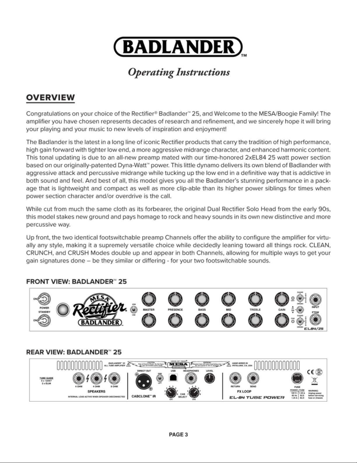
Also included in each Channel is our patented Multi-Watt™ power switch rounding out the Front Panel options
with power choices of FULL at 25 watts and HALF power at 10 Watts. These power options, with their specific
headroom thresholds and characteristics, add versatility and color to the preamp’s many choices, resulting in
sounds that are as authentic as they are inspiring to play
Looking to the Rear Panel, features include, first, a full complement of SPEAKER OUTPUTS with two 4 Ohm and
one 8 Ohm jacks, enabling a wide array of impedance matching options for your favorite cabinets and most
popular speaker configurations.
Next, the onboard CabClone™ IR DI Section opens a new world of flexibility and convenience, providing 8
choices (repeated in each Channel) of Impulse Response Captures of our most popular MESA Speaker Cabinets
miked for Live applications. This channel-specific ability to assign your cabinet IRs means you can treat clean
and overdrive sounds dierently, applying just the right cabinet style (sealed or open back) and speaker type
(ceramic or alnico) for optimized performance, live or in the studio, consistently and conveniently.
These can be used live with the speaker active for a mix of miked and direct feeds or in Silent Mode for studio applications with the great feel of your amplifier remaining intact. This is possible in part due to the great
sounding, great feeling built-in reactive Load that allows integration of the power section and all its character
and dynamic components without the need for a speaker cabinet connected for protection of your output
transformer and tubes.
This addition makes the Badlander a mighty ri-catcher as the first MESA amplifier to feature such comprehensive, convenient, and inspiring DI performance. With the Badlander’s vast preamp versatility, power options,
and the fact you can record or perform “silently” and safely with no live speaker as well as direct mixed with
your favorite Cab miked up, it sets a new standard for Tone, feel, and convenience in capturing your own brand
of electrified guitar magic direct.
The interface points and features of this powerful inclusion appear as follows: a standard 3-Pin XLR for the balanced DI signal, a Circuit-to-Chassis GROUND/LIFT Switch, a standard USB port to interface with your computer
for File manipulation/transfer/downloads, a HEADPHONE Output, a LEVEL control to adjust the DI Output and
Headphone level, and a pair of CAB SELECT 8-position Rotary Switches enabling you to call up the dierent
Cabinet choices for each preamp Channel.
The CabClone IR circuitry also supports third-party IRs and the processor can hold, depending on File size,
hundreds of IRs in its Storage Library. Simply connect the Badlander to your computer using the USB port and
manipulate the IR Files in accordance with your needs.
Next on the Rear Panel the Badlander includes a no-compromise buered serial EFFECTS LOOP that provides
a patch point between the preamp and power section for seamless integration of processing you don’t want
on the amp’s Input. Time-based Eects such as Reverb, Delay, Chorus, Flange, and in some cases, even things
like compression, are all candidates for use in this Tone-preserving EFFECTS LOOP.
The Fuse Holder rounds out the Rear Panel. Always use the proper rating for your particular model in a Slo-Blo
type package.
Now it’s time to get to the information that will help you get the most enjoyment out of your new amplifier.
PAGE 4
Page 8
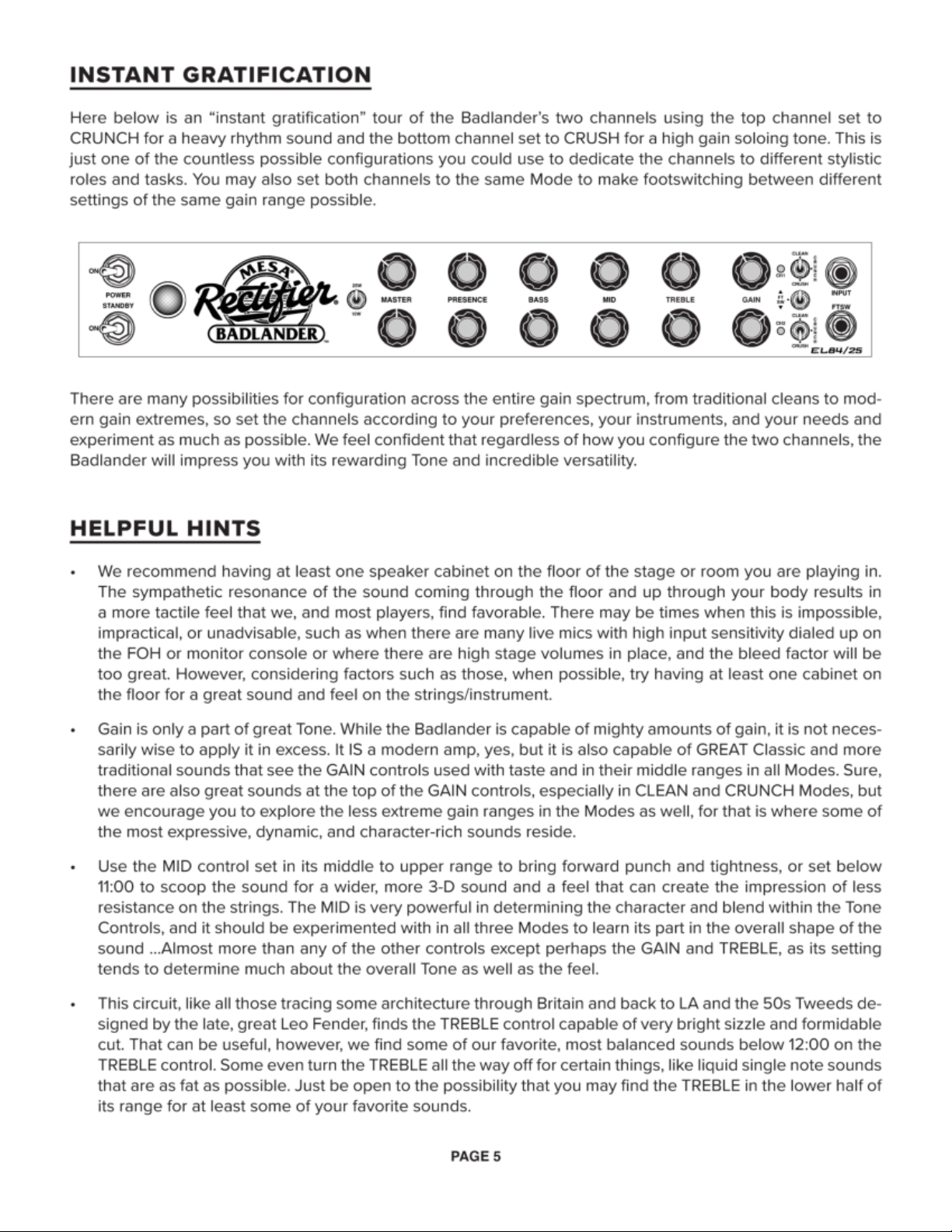
Page 9

• The MID control carries a fair amount of top end along with the previously mentioned punch, albeit in a
lower place than that of the TREBLE. Keep in mind it can also be used to bring in attack and openness of
a dierent character than that found in the TREBLE.
• The PRESENCE also plays its role in the overall top end and open-sounding quality of the mix and, at times,
in a more pleasing, higher, and more global range than that found in the TREBLE’s upper region.
• We encourage you to experiment with all three of these controls above when searching for your perfect
blend of top end, as they each represent a dierent region of the spectrum and together provide the tools
to achieve a great blend if you spend the time working with them.
• When searching for more traditional-gain Crunch or Classic Rock sounds, especially in the CLEAN Mode, you
may want to try the reduced wattage position of the Multi-Watt Switch in addition to simply turning the GAIN
control higher. Taking this approach allows for you to increase the overdrive content and characteristics in
the power section with the MASTER control, which the EL84s oblige to no end when pushed, while at the
same time lowering the overall output volume to make dB levels less impactful for yourself and others who
may be nearby on the Bandstand or in the audience.
• When using the EFFECTS LOOP to interface your outboard processing, use good quality shielded Audio
cables of the shortest length possible to assure the best performance and least chance of signal degradation. Remember that anything you insert into the middle of your amplifier can act as a Tone shaping device,
so we recommend high-quality eects processors and good quality cabling to assure the best chance of
avoiding degradation. Though the Eects Loop is buered and, in theory, should be somewhat impervious
to Tonal thievery, your entire signal will be subjected to whatever the lowest common denominator is in
your signal path, so take note of this and choose your processors and cabling accordingly.
• The 8 Factory-Loaded CabClone IR selections that each channel of your Badlander can hold at one time
were chosen from the BANK A/LIVE Presets as they appear in our CabClone IR standalone unit. They were
selected for their ability to sound open and sit well in a variety of mix applications, from stage performance
to recording and from small combos to more dense mixes with multiple instruments and voices. See the
CabClone IR Section of this Manual for more information.
NOTE: When manipulating IRs within the MESA IR Drive, each memory location within the 8 Presets in the MESA
IR Drive must contain one IR and one IR only. Placing two IRs in each - or any - of the locations or having no
IR at all in a memory location will result in having a blank location, and there will be no sound at all in that corresponding location on the Cab Select Rotary.
NOTE: It is normal to hear a scratchy sound while turning the Presence Control. The Badlander employs a power
section-based PRESENCE circuit and there can be a small amount of DC voltage on the PRESENCE pot, which
is audible when you turn it. This is completely normal and there is no need for concern or servicing.
FRONT PANEL
INPUT
This is the Instrument Input on your Badlander. Always use low capacitance, shielded Audio cables of good
quality and, whenever possible, in lengths below 18 Feet …preferably 15 feet or less. The Badlander is capable
of extremely high gain, so noise in the instrument cable has the potential to be amplified many times depending on your application and settings. So again, use high quality, low capacitance, shielded instrument cable
between your instrument and the amplifier’s INPUT.
FTSW.
This mono 1⁄4” jack is the Footswitch jack for the included MESA Channel Switch. When the supplied Footswitch
PAGE 6
Page 10

and cable are connected here, you may select the Channels remotely instead of using the Front Panel Channel Select switch located just to the left (or to the right on the Combo version) and between the Mode Select
switches for each Channel.
CHANNEL SELECT
This switch in the center of the stacked switches allows manual selection of the Channels when the Footswitch
is not plugged in or available. The Center position labeled FTSW accommodates the Footswitch when plugged
in to the adjacent FTSW jack and allows remote switching between the Channels via the Footswitch. Make sure
the switch is in the Center position when using the Footswitch. Otherwise, the switch moved upward selects
Channel 1, the switch moved downward activates Channel 2.
MODE SELECT
These mini toggles above and below the Channel Select switch select the Modes in each Channel. In a sensible
fashion, the gain of each Mode increases as the switch is toggled downward. The Channels are identical, so
the switch operates the same way triggering identical Modes in each of the two Channels.
GAIN
In the Badlander, as with most MESA amplifiers, the GAIN is the most critical of all preamp controls. Its setting
determines much about the character and texture, dynamic content, and sustain factor of the sound and effectively pre-voices the sound in all three of the (identical) Modes appearing in both Channels.
Each mode reacts a little dierently, but generally speaking, the middle range of the GAIN control provides
enough of everything and not too much of anything. Most of the middle range is supremely useful for almost
any style. Best of all, here, the instrument will sound like the instrument, as its character won’t be overshadowed
by saturation of the various tube stages.
For classic sounds, we recommend GAIN be set in the lower to middle region, somewhere between 10:30 and
2:00. This is where you will find the best blend of dynamic preservation and attack mixed with fullness and
sustain, again, without completely saturating the sound and covering up instrument’s character.
One good thing to remember is that the lower the GAIN control is set, the more transparency and top end you
will retain. As the control is increased, the top end will start to recede, and a fuller, fatter sound will emerge until,
eventually, it will be very fat and compressed and possibly even a little slower feeling along with the added
drive and sustain.
Another handy and reasonable approach is this; As GAIN goes up, BASS should come down. That is a very
general, broad-sweeping approach, but it is a fairly good way to preserve definition and attack characteristics
and keep your dynamic content as prominent and intact as possible. Still, reducing the BASS control can’t nullify the compressing and darkening eects created by very high GAIN settings. It helps with the frequencies in
regard to preserving the attack, but it can’t counterbalance what happens to the dynamic characteristics. The
best way to preserve dynamic content is by using restraint and common sense with the GAIN control.
The higher region of the GAIN Control is appropriate for Classic, 70s style Rock or overdriven Blues sounds
in the CLEAN Mode, and Heavy sounds in CRUNCH and CRUSH. From 2:00 on up to 5:30/maxed, the sound
becomes very overdriven and filled with harmonic complexity. There are amazing sounds up here, you just
need to learn the ways to preserve attack and clarity through working with the BASS and other Tone controls,
as well as the overall MASTER setting, to retain as much attack and definition as possible.
Start by observing the rule of thumb outlined above: reducing BASS while increasing GAIN, and you should be
headed in the right direction. From there, some fine-tuning elsewhere in the Tone Controls where appropriate,
but once you’ve familiarized yourself with the frequencies and the interaction between the controls, it shouldn’t
take long to achieve a great blend.
Also, many players into heavy styles and fast tempos looking for the best blend of the highest gain and the
tightest tracking low end possible tend to avoid cranking the MASTER up past the point where you can start
PAGE 7
Page 11

to feel the power section working and stop before it is being pushed into clipping.
When the power section is pushed into clipping with high volumes, the tracking and dynamic character change
as the recovery time of the power supply starts to increase. There may be times to include power clip as part
of the authentic ingredient to a sound, like blues sounds or classic rock sounds in the Clean Channel cranked.
However, you will find the best overall tracking and dynamic response for most styles in the middle range
(10:00 - 1:30) of the MASTER controls/overall power output.
By all means, when possible, turn the amp up enough to get the power tubes working and doing their magic,
adding fullness and color, but more than that isn’t always better. Going past there, adding color to the onset
of clipping and farther into saturation will present trade-os in tracking and articulation, especially in the low
end and especially when higher GAIN settings are also applied. Like most of the controls on your Badlander,
for most sounds, we suggest using the MASTER controls, and hence overall power, in the middle range for the
best overall response and performance.
Another way to add harmonic content is to incorporate the POWER SELECT switch and switch down to the
lower wattage setting. This approach will allow you to increase the MASTER and hear more of the power tube’s
character, but this too must be balanced to assure the low end stays tight and the tracking isn’t compromised.
The best tracking and low-end accuracy will most always be experienced in the highest wattage setting. So, if
your music requires accurate Bass response, especially in combination with high GAIN settings, you will want
to forego the extra harmonics that might otherwise be added in the lower wattage settings and just stick with
the highest Power Setting.
TREBLE
While the GAIN is the most powerful control in the Channels, the TREBLE runs a close second. The TREBLE is
responsible for shaping the character of the Mode almost as much as the GAIN. It also tends to overshadow
almost everything except PRESENCE, seeing as these two controls deal with top end and that is always what
reaches your ears fastest/first. Since the TREBLE can overpower the rest of the Tone controls easily, its setting
is crucial to a rich and balanced sound in all three of the Modes. Setting the TREBLE with care and taste in mind
is also critical for the Tone control string to work in harmony.
In all three Modes, the middle region of the TREBLE delivers the best balance and creates sounds that are
plenty bright enough but still possess richness and warmth. We suggest that you start with the TREBLE at 12:00
and adjust up or down slightly until the desired blend is achieved.
Circuits emanating from the Brit side of the tube amplifier spectrum and sharing that DNA tend to favor TREBLE
and PRESENCE control settings on the lower side for the best blend of attack and warmth. Depending on guitar
woods, pickups, and technique, don’t be surprised if you find great sounds below 12:00, or even all the way
down on the TREBLE and the PRESENCE as well, on occasion. The MID’s broad Q carries substantial top end,
and sometimes it is capable of providing all the cut you need.
The MID control also carries frequencies somewhat close to those the TREBLE commands along with the upper mid and lower mid frequencies it is centered around. Use this to your advantage and experiment with setting the TREBLE lower than you normally might and running the MID up a bit and vice versa. Some very cool
sounds can be found with the TREBLE lower, very low, or even o, and the MID higher than you may be used
to. Be sure to check the interaction between these two powerful controls, as it will be critical in achieving the
sounds you want.
MID
The MID control, while perhaps not quite as powerful as the GAIN and TREBLE controls, does impart a strong
character on the sound of all three Modes. MID brings in and out a broad band of midrange frequencies and
– as we have mentioned earlier in the TREBLE section – along with these frequencies rides a fair amount of
higher “low treble” range frequencies. These highs are lower than those the TREBLE carries, but they are im-
PAGE 8
Page 12

portant for the punch and cut in a mix. They are also important to the way the amp feels to play (forgiving or
more forward and even sti).
These midrange frequencies exhibit an interesting trait; At lower settings where the mids are scooped out,
leaving big low end and open, soaring top end, the strings can feel more forgiving, bouncy, more elastic, and
easier to play. Conversely, at higher settings of the MID, where this frequency creates a bump and lows and
highs are somewhat overshadowed by midrange frequencies, the sound becomes more forward, and the
response can feel to some players less forgiving and even sti to play. Setting the Mid higher doesn’t change
anything in the physical sense other than your perception, however depending on how much you rely on the
relationship between what your ears hear and the tactile sensation your hands feel, you may want to give your
ears and your hands some extra time to adjust to the varying dierent EQ curves.
Guitar is a very tactile instrument and, like an acoustic instrument, is sensitive to the environment …the room it’s
played in. Electric guitar is also aected by and dependent on the frequencies manipulated and cut or boosted
in the amplifier’s preamp.
All these factors play a part in your perception of how the instrument responds to your attack, how the sound
morphs afterward, and how it feels to play as your ears capture it, your brain interprets it, and then sends signals
to your hands while playing in this feedback loop.
This is a highly interactive experience, and the relationship between electric guitar and amplifier – at least a
tube amplifier - is symbiotic. Spend time learning and playing with the interaction between the controls and
also between your guitar and the amp. With an acoustic instrument where much of the sound you hear and
feel is based on room characteristics, here the controls can be used together to shape not only the sound but
also, through interpretation, how the instrument feels in your hands. The MID, as much as any of the controls
and perhaps even more so, showcases this phenomenon.
BASS
The BASS is an easy to understand and gratifying control as well as being forgiving in terms of settings...except
when, as mentioned, high gain is involved. For clean playing in the CLEAN Mode, large amounts of BASS can
be applied with very little worry as to detrimental eects. Fullness and body, warmth and girth are its benefits
as the control is increased past 11:00, with most players finding all the low end they need by about 1:30 or 2:00.
For overdriven sounds in all three Modes, you will need to apply the previously mentioned suggestion; As Gain
goes up, the BASS should come down. Failure to apply this rule may result in tubbiness and a compromised
attack characteristic. This is especially true with the highest region of the GAIN control. A little BASS can go a
long way when this much gain is applied, and in CRUNCH and CRUSH Modes, you may find that 11:00 or 12:00
is the highest you’ll ever need for a great sound.
You can probably get away with the BASS as high as 1:30 or 2:00 for blues, nu-country, roots, and indy rock
sounds where the GAIN control is below 2:00 in CLEAN or CRUNCH. For classic rock sounds in CLEAN, where
the GAIN is maxed, you will likely want to use settings below 11:00 to keep the low end tight and dynamic. Use
a little restraint, common sense, and good taste, and you’ll find great sounds in all three Modes with plenty of
low end available to make things sound and feel huge.
PRESENCE
This control adjusts high frequencies - above those of the TREBLE - and is farther downstream in the signal
path than the Tone Controls. It works with negative feedback and allows adjustment of the top end in the power
section and its placement there is part of achieving its urgent character and its ability to help you hit hard when
you need cut in a dense mix or round out the edges and create a more vocal, rounder sound.
You can think of the PRESENCE as a control that allows you to either clamp the highs down in the power amp compressing and darkening things - or open the power section up and let the full spectrum of upper harmonics
come blazing through. It also has a great deal to do with how dynamic the signal is and, as mentioned, how a
PAGE 9
Page 13

given sound will cut through the mix in an ensemble environment.
At low settings (7:30 – 10:30), the sound will be warm and round with a more compressed feel, and dynamic
fluctuation will be somewhat tamed-down. As the PRESENCE is increased (11:00 – 2:30), the top end becomes
more dominant, and that compression gives way to “cut,” and dynamic peaks jump out with startling speed and
accuracy, unleashing the Badlander’s wilder side.
Clean sounds in Channel 1 can generally benefit from slightly higher settings (10:30 – 12:30) than sounds that
have overdrive involved in their makeup.
Once saturation begins, the frequencies carried in the PRESENCE control need to be administered with care,
as too much top end applied in the power section can create edgy, unpleasant, or even painful sounds. Set too
high, it starts to separate the high frequencies from the rest of the notes, resulting in a buzzy, detached Tone
...something you probably don’t want!
Overdriven chording sounds can tolerate higher settings (10:30 – 12:30) better than single notes, which usually want to roam the zone below 11:00 to stay round, focused, and sound as big, wide, and vocal as possible.
At the top end of the control (2:30 – 5:30), an aggressive blend of upper harmonics dominates the sound, and
this region can be somewhat dangerous to balanced Tone if it’s not applied in small measures. Higher notes
will slice and dice even the bravest of ears, and we suggest using this region mostly in the studio for recording
heavy crunch rhythm parts, and even then, on parts that feature mostly the lower strings. This region – especially
when coupled with the inherent curve of many of the microphones typically used in P.A. (sound reinforcement)
applications, can be truly punishing to both bandmates and audience alike.
It’s especially important in terms of PRESENCE settings to check the “line of fire” if you are standing very close
to and/or in front of your Cabinet(s)!
Remember, the aggressive highs you may want to dial up with the PRESENCE in an attempt to hear yourself
“cut through” that are hitting only your legs will be hitting microphones and/or the audience directly. What you
hear standing right over your Cab when you’ve got the TREBLE and/or PRESENCE set high will be WAY dierent - and less punishing - than what hits the mic’s diaphragm and the audience’s heads and ears.
NOTE: In the name of great and balanced Tone, we’d like to humbly suggest putting your head down by your
speakers now and then (but not for too long!) to ensure your Tone is really what you think it is.
So often, in small to medium Venues, the tendency is to dial in WAY more brightness than you really need
because you’re often standing almost on top of your Cab. More times than not, that means you aren’t hearing
all that extra top end you might think you need. It may take some getting used to at first, but you can learn to
hear a darker, warmer sound found lower on the TREBLE and PRESENCE controls, and your sound will be FAR
more pleasing and balanced at the Front of House and in the first few rows of the audience.
The lucky few playing mostly large venues are more apt to learn this early, as their greater distances from their
cabinets on big stages help reveal the excess top end quickly. And if they don’t, the Front of House Engineers
help out in short order. The rest of us performing in small to mid-size venues tend to learn this the slow way
or need to get the tip-o from veteran associates or adept FOH Engineers. Either way, your audience, your
recordings, and even your own ears over time will benefit from this more respectful, tasteful approach to top
end in your Tone.
NOTE: It is normal to hear a scratchy sound while turning the Presence Control. The Badlander employs a power
section-based PRESENCE circuit and there can be a small amount of DC voltage on the PRESENCE pot, which
is audible when you turn it. This is completely normal and there is no need for concern or servicing.
MASTER
This control determines the overall output level of each Channel and is located at the very end of the circuit,
PAGE 10
Page 14

just before the Driver stage. By using it in combination with the GAIN control, any amount of preamp signal
strength – gain – (within a Channel’s parameters, of course) can be achieved at any playing volume. Once you
have dedicated the Channels to their respective sounds, you can then balance the volume levels of the Channels using the MASTER controls.
For general applications and to get the best performance out of the Channels, we recommend MASTER settings in the 9:00 – 12:00 range, with most people settling in around 10:00 – 11:00 for average playing volumes.
Some purists like to run the MASTER all the way up and raise the GAIN until they reach their desired sound–the
thinking there being that this achieves the “purest” sound. The belief is this resembles removing the control
altogether from the signal path, and in a way it does. However, most all the “vintage non-master” amplifiers
have discrete resistors in that place in the circuit anyway to adjust or “tune” the output of the preamp to the
power section’s sensitivity.
The MASTER is nothing more than a variable resistor that oers an infinite range of settings possibilities between the preamp and power section, which makes the amplifier many times more versatile with basically no
sonic penalty. The main dierence being perhaps the carbon element in the pot might have slightly dierent
characteristics than a given fixed resistor. That said, not only do we test for that and choose the best sounding resistive element material, but also, it’s hard to fairly determine what the dierence might be, as playing
volume aects how the amp (and speakers) respond and impart their signatures to shape your perception of
those qualities at a given volume.
If you prescribe to the above old school approach, then, by all means, use the MASTERS in this way... it won’t
hurt the amplifier. However, realize that you may be severely limiting the sounds you can achieve by removing
the limitless great-sounding combinations of GAIN and MASTER settings.
NOTE: VERY high settings of the Master combined with high output pickups can potentially overload the input
of the IR circuitry, causing unwanted distortion. If you notice some unpleasant clipping at the IR Output with
the Masters high or all the way up, turn the Master down until it goes away and readjust the Input Trim Level
on your interface or console to make up the gain dierence.
MULTI-WATT™ POWER
This 2-position mini toggle allows the selection of one of two dierent power ratings. The upper position runs
both EL84s in Pentode wiring for approximately 25 watts of power. The lower position on the toggle provides
a low-power setting in which the two power tubes run in Triode wiring and produce approximately 10 watts of
power. Each of these power settings has its own tonal character as well, and this provides yet another way to
shape and color your sounds.
25 watts (Full Power) produces the biggest sound and most girth, most accurately tracking low end response
and fullness in the lower mid-range that speaks with authority and punch. 25 Watts is also capable of the loudest clean headroom and sheer output volume in the overdrive Modes. Soloing in the 25 Watt setting will deliver
the most authority, dynamic sensitivity, and sonic width, so we like it best when it’s time to shine, especially in
dense mixes recorded and/or live.
10 watts reconfigures the power tube wiring to Triode style, which is a more vintage configuration that produces less power and is associated with a sweeter, smoother transition to clipping and, some feel, a warmer
sound. Here it is included for its reduced wattage and therefore lower volume capability, as much as for its
tonal characteristics. The 10 Watt setting allows you to drive the power tubes into clipping more easily should
that be desirable and incorporate even more of their character into your sounds in the Modes.
The reduced wattage comes with some tradeos, and the first you will likely notice is a reduced tightness in
the low end, potentially aecting its accuracy in tracking. For heavy sounds, especially those used for very
precise rhythmic parts, the 25 Watt/Full Power setting will be a better match.
If you are recording or simply enjoying the Badlander in your home for more classic rock sounds and other
PAGE 11
Page 15

styles where tight tracking low end isn’t the priority, and you don’t need high volume levels, the more traditional
side of the first two Modes is potentially enhanced by the Triode operation of the tubes. CLEAN wound up,
and CRUNCH set somewhere on the lower 2/3 of its GAIN range both reveal really cool, more traditional-gain
classic rock, nu-country, and even blues sounds in the lower 10 watt setting.
POWER - AC
This 2-position toggle switch controls the delivery of the AC Mains power to the amplifier. Make sure your included power cable is connected securely to the IEC Socket on the Rear Panel and the male 3-terminal plug
connected to a Grounded 3-Leg AC Wall Socket supplying proper voltage. US Domestic @ 117-120 Volts AC.
NOTE: WARNING! Never alter your Power Cable in any way! Doing so will void your warranty and put you at risk
of electric shock.
From a cold state, always follow the Cold Start procedure below so that cold power tubes and their filaments
have a chance to warm up before being hit with high voltage. Doing so will prolong the toneful life of your tubes,
especially your power tubes, but it also doesn’t hurt - and if anything helps - even your preamp tubes last longer.
COLD START PROCEDURE
1. Flip POWER To “ON”
2. Wait (at least) 30 Seconds to allow tube filaments to warm up.
3. Flip Standby to ON.
It is wise to do this every time you have let the amplifier cool for any length of time.
STANDBY
As mentioned above in the POWER section, the STANDBY provides a warm-up/idle state for the tubes – and
also a Mute of any sound – in your amplifier. It should ALWAYS be used at power up, even if the amp’s chassis
is warm to the touch from recent use. This is in part because tubes cool far more quickly than other components, and even when they are warm, it is far easier on them to have 30 seconds of warm-up time before they
are hit with the high voltage.
The STANDBY also doubles as a mute feature for set-up before and breaks during a performance. Use the
STANDBY any time you are pausing from playing and want to keep your amplifier in a warm and ready state.
If you’re going to take a break for a couple hours, it’s probably best to power down to save electricity, just be
sure to use the Cold Start Procedure (listed under the POWER instructions above) when you return and want
to power back up and use the amplifier again.
NOTE: The following information is also found in the Troubleshooting Section in the rear of this Manual, but since
the STANDBY is a helpful tool in tube swapping, here’s a little preemptive troubleshooting tip and knowledge
that you might never need but is good to know as a tube amp owner.
STANDBY: Tube Issues/Troubleshooting
Should you ever flip the STANDBY to ON and hear a loud hum, loud static, or should you smell something hot/
burning, quickly flip the STANDBY to OFF. What you could potentially be hearing (or smelling) may be a power
tube arcing or shorting.
While this is rare, it can happen if a power tube were to become faulty. Though less common, in some cases, a
faulty power tube can cause the tube it is paired with to run away and become faulty or red hot in the center as well.
In the event this ever does occur, flipping the amplifier to STANDBY stops the incident right away. On occasion,
it will correct the problem, but often if the tube has a problem it will reoccur. You can troubleshoot and correct
the problem (with some spare known-good tubes) using the STANDBY switch and the method outlined below:
PAGE 12
Page 16

While looking at the Rear of the amplifier and watching the power tubes (you may need to move the Tube Cage
by unhooking the nylon clips and moving it out of the way or removing it altogether), flip the STANDBY to ON.
If a power tube(s) is arcing or shorting, you will likely see it flashing brightly rather quickly, or if “running away,”
perhaps glowing red hot in the tube’s center metal parts more than the rest of the set. As mentioned above, on
occasion, an arcing or shorting tube can pull its paired counterpart out of bias and cause it to run away as well.
Regardless, flip the STANDBY to OFF.
Get an “OV-Glove” or similar method of hand protection (leather gloves, a rag, etc.) to grab the hot tube with.
Do NOT use your bare skin as the tubes will be very HOT!
After the Tube Cage has been removed and the tubes are accessible, push up the spring steel Tube Clamp(s)
and gently rock the faulty tube back and forth slightly while pulling it down and out of its socket, noticing the
orientation of the 9 pins (on the smaller EL84s) in the Badlander 25 and the gap between them in the circular
pattern, or the tube guide (raised bump) on the plastic piece in the center of the tube’s base (6L6/EL34s in the
Badlander 50 and 100) When it’s time to install a new tube you will need to line up the pins or plastic guide
according to the gap (or slot in Octal Tube Sockets) in the tube sockets mounted in the chassis.
Gently and slowly, install a new tube of the same type and color rating (preferably matched MESA Tubes) as
the one(s) removed if possible. Make sure to line up the gap in the tube’s pins (or plastic guide bump with the
slot in the tube socket’s center hole). Make sure the tube is seated completely in the tube socket and that the
tube filaments light up.
NOTE: With the POWER switched ON, if the tube’s center does not light up/is glowing orange, check the tube’s
orientation in relation to the gap in the Pins (or guide slot in the tube socket Badlander 50/100) and that it is
seated firmly and completely into the socket.
Flip the POWER switch to ON and wait at least 30 seconds.
While watching the rear of the amplifier - and specifically the (replaced) power tubes again - flip the STANDBY
switch to ON.
If you do not see any unusual flashes or brightly glowing (red hot) metal in the center of any of the tubes, you
have remedied the issues and are ready to play.
If you see a flash or the center of the tube glowing bright red in the center of the metal inside the glass, repeat
the steps in this troubleshooting section again using another/dierent power tube(s). If that does not remedy
the problem, the faulty tube(s) may have burned a resistor, and it will need to be replaced by a Service Technician. The latter is pretty rare, and most tube issues, if caught in time, can be remedied with this troubleshooting
procedure and a couple of “known good” tubes.
REAR PANEL
SPEAKER OUTPUTS
One 8 Ohm and two 4 Ohm jacks are provided for speaker interfacing. The Badlander is not very sensitive to
speaker mismatches and will not be damaged by them, except that very low impedance loads such as 2 Ohms
will cause the power tubes to wear faster and put undue stress on the output transformer and therefore are
not recommended.
A single twelve-inch 8 Ohm speaker, such as in the Combo, should be connected to the 8 Ohm output. When
using two 8 Ohm speakers, connect them both individually to the 4 Ohm outputs provided (because the total
load is 4 Ohms in this case.) Check out the information further back in this manual regarding speaker impedance and possible speaker hook-up schemes.
PAGE 13
Page 17

4x12 cabinets may be 4, 8, or 16 Ohms. If you are not sure of the impedance of your cabinet, you may need to
remove the Rear Panel in order to verify the impedance rating of the individual speakers. MESA/Boogie 4x12
and 4x10 cabinets come wired to 8 Ohms standard and are wired in series-parallel. Some Non-MESA 4x12 cabinets are wired 16 Ohms using four 16 Ohm speakers. By wiring all four speakers in parallel, you can reduce the
cabinet to an impedance load of 4 Ohms (assuming the speakers are 16 Ohms each.) No matter how unusual
your speaker setup is, it is always possible to get good performance.
NOTE: Normally, this is the spot we’d be reminding you to ALWAYS keep a Load connected to your amplifier.
However, your Badlander is wired such that when you disconnect the (Speaker) Cable from one or more of
the SPEAKER output jacks, the Internal Reactive Load is automatically connected. This means your amplifier is
always protected from a no-load condition. Still, when using Tube amps, it is important to remember they need
a load. So, if you own other tube amplifiers, make sure you don’t forget to check this important connection to
keep your amplifier safe.
NOTE: The Badlander 25’s 10 Watt Triode setting on the Multi-Watt Power switch rewires the tube’s wiring style
(Pentode to Triode), and even though this produces less power, the number of tubes in use does not change.
Therefore, there are not the same impedance changes present as would be in our 4-tube higher power models
with larger wattage reduction dierences on some of the Multi-Watt power positions. Regardless, you may try
using the 4 Ohm Speaker output with your 8 Ohm cabinet for a softer attack, scooped midrange, and sweeter
top end (along with a little less power). If you prefer the scooped, slightly sweeter response the mismatch of
the 4 Ohm speaker output creates, feel free to use it, as it will not harm your amplifier or speaker. Some players prefer this softer, less forward sound and even cite its less resistive, more inviting feel. Experiment to find
what suits your style and applications best.
CABCLONE IR DIRECT INTERFACE SECTION
This section of the Rear Panel is dedicated to the CabClone IR, which, as mentioned previously, allows for quick
and convenient capturing of your amplifier through our most popular cabinetry Direct with no need for miking.
This is made possible by the great sounding, great feeling built-in Reactive Load that allows integration of the
power section and all its character with no speaker cabinet connected. The feature is a welcome addition for
anyone doing frequent tracking as well as live playing. The all-inclusive approach brings on board mighty DI
performance, and when combined with the Badlander’s vast preamp versatility and the fact you can record or
perform “silently” and safely with or without your favorite cab, puts the Badlander in top-of-class status. All that
means you can capture your ideas more quickly and easily with far less in the way of your creativity.
The components of the CabClone IR DI section are as follows:
• Standard 3-Pin XLR for the balanced DI Output signal.
• Circuit-To-Chassis Ground/Lift Switch.
• Standard USB port to interface with your computer for File manipulation/transfer/downloads.
• HEADPHONE output - Stereo
• LEVEL Control to adjust the DI Output and Headphone level.
• A Pair of CAB SELECT 8-position rotary switches that allow 8 dierent cab/Mic choices for each
preamp channel.
The CabClone IR circuitry also supports third-party IRs and the processor can hold, depending on File size,
hundreds of IRs in its Storage Library. Simply connect the Badlander to your computer using the USB port and
manipulate the IR Files in accordance with your needs.
Upon connection to your computer through the USB port, you will see MESA IR in an icon much like a USB
Stick Drive. Once opened, you will see three separate folders. These folders are labeled Channel 1, Channel
2, and Cab Library.
PAGE 14
Page 18

MANIPULATING/STORING IR FILES
As mentioned in the Overview, the Badlander, the first ever to include our CabClone IR DI, opens up a new world
of flexibility and convenience. The 8 choices (repeated in each Channel) of Impulse Response Captures of our
most popular MESA Speaker Cabinets are a HUGE time-saver and inspiration-preserver when you can’t use
Cabs or don’t have the environment suited for great room recordings. The array of IRs provide great choices
in the very best of virtual cabinetry and gives you 8 instant voicing options, as well as footswitchable independence to treat the two channels dierently when recording direct or sending live mic-free stage sounds to the
front of house in performance venues.
The Channel 1 and Channel 2 Folders contain the same 8 “LIVE” Captures found within BANK A of our standalone CabClone IR and IR+ units. These were captured using Condenser and Ribbon microphones and are
brighter and more open sounding to allow being better heard in Live or dense mix applications.
The MESA Cabinets featured in the 8 “LIVE” Presets of both Channels are as follows:
1. 4x12 RECTO STANDARD – Celestion V30s – MESA Proprietary – 8 Ohm
2. 4x12 RECTO TRADITIONAL – Celestion V30s – MESA Proprietary – 8 Ohm
3. 2x12 RECTO HORIZONTAL – Celestion V30s – MESA Proprietary – 16 Ohm
4. 1x12 RECTO – Celestion V30 – MESA Proprietary – 8 Ohm
5. 1x12 THIELE – Celestion C90 – MESA Proprietary – 8 Ohm
6. 2x12 LONE STAR – Celestion C90 – MESA Proprietary – 16 Ohm
7. 1x12 LONE STAR 23 – Celestion C90 – MESA Proprietary – 8 Ohm
8. 1x12 CALIFORNIA TWEED 23 – Jensen 100w Alnico “Blackbird” – 8 Ohm
The Cab Library Folder contains enough memory space, depending on their file size, to hold hundreds of thirdparty IRs. With room and power to store and manipulate sounds for your direct needs, the Badlander has the
potential to be a super versatile sound palette for many of your guitar needs, be they on stage or in the studio.
NOTE: When manipulating IRs within the MESA IR Drive, each memory location within the 8 Presets in the MESA
IR Drive must contain one IR and one IR only. Placing two IRs in each or any of the locations, or no IR at all in a
memory location, will produce the same result as having a blank location, and there will be no sound at all in
that memory location on the Cab Select Rotary.
NOTE: Regardless of what IRs are loaded into the CabClone File Folders for each Channel (the Factory IRs or
custom 3rd party IRs), the individual Preset Folders for each Channel must contain the same IRs loaded at
each Preset location (1-8). For example, Preset location 1 in Channel 1 must have the same IR loaded into the IR
Folder as Preset location 1 in Channel 2. You can use dierent Presets across the Channels, but the matching
numbered rotary positions must each call up (be loaded with) the same IR File.
NOTE: Important!! Don’t forget to eject the CabClone IR Drive just as you would a Flash Drive when you are
done manipulating the IRs.
And finally, perhaps one of the most valuable uses for the CabClone IR feature on the Badlander lies in its use
as a personal practice tool via headphones at home, backstage, or wherever you might want to apply its great
tone and feel without necessarily having to share it with others.
DIRECT OUT
This standard 3-Pin Male XLR is for connecting to your Recording Console, a Front of House Mixer, or the Monitor
Board. Cable length is usually fine, up to 75 Feet or so, as it sends a Balanced Signal. The Level is determined
by the LEVEL Control here in the CabClone section and the setting of the MASTER controls on the Channels.
PAGE 15
Page 19

NOTE: It is always a good practice to zero out the Channel and Master Faders on the destination Console and/
or Interface, as well as the LEVEL on the CabClone IR section of your Badlander, BEFORE connecting the cable
to the DIRECT OUT. This routine will help avoid unwanted (hot) signals accidentally sent during hook up from
damaging your ears and those of others, monitor speakers, etc.
GND/LIFT
A mini toggle Ground switch is provided, which can lift the circuit Ground from the chassis Ground. This “Ground
float” switch can be helpful in eliminating some Ground loops caused by dierent references to Ground between
Consoles, Interfaces, and the CabClone IR circuitry.
Always start with the unit set to the GND (GROUND/upper) position when connecting the unit to a Console.
If you experience noise in the form of hum or buzz, you can try the LIFT (lower) position to see if perhaps the
noise you are experiencing is caused by a dierent Ground reference between the Console and the CabClone
IR/amplifier. The switch does not always cure the noise problems associated with these dierences in Ground,
but it is often eective, and a welcomed feature when you’re anxious to get rolling in the Studio or do a timely
Sound Check at a gig.
CAB SELECT
These two 8-position rotary controls select the Cabinet IRs you will trigger in each of the Badlander Channels
when connected to the DIRECT OUT and/or the HEADPHONE Output.
Having separate rotary controls for each Channel allows you to set the Channels dierently and optimize each
Channel’s gain region, sound style, and response with a Cabinet best suited to what you’ve dialed up with the
Mode Select, GAIN, Tone, and MASTER controls. This kind of flexibility puts the Badlander in a new category
in terms of direct recording with a tube amp, enabling you to further authenticate your footswitchable sounds
with a virtual Cab/IR that will not just broadcast them but rather showcase them.
USB
This standard USB port accepts a 2.0 A to B cable (not included) and is provided for connecting to a computer
for managing the IR File directory. If you don’t have a 2.0 USB Cable around the house, it’s an easy Cart add
at many online Retailers or available in most Music or Tech stores.
The CabClone will appear on your Computer’s Desktop much like a USB Flash Drive and, once opened, will
show you 3 separate folders labeled: Channel 1, Channel 2, and Cab Library. Each PRESET location on the
8-position Cab Select Rotary has its own File within the two Channel 1 and Channel 2 folders, and they contain
the same 8 “LIVE” IRs as loaded from the Factory.
NOTE: Important!! Don’t forget to eject the CabClone IR Drive from your computer’s Desktop just as you would
a Flash Drive when you are done manipulating the IRs.
HEADPHONES
A standard 1⁄4” stereo phono jack provides the Output for Headphones. This allows the Badlander to be not
only a wonderful live performance and Recording ally but also a great tool and companion for “Silent” practicing when you can’t make any “noise” for those around you.
Like the Balanced XLR DI OUTPUT, the volume level at the HEADPHONES Output is determined by the LEVEL
control. It’s not a problem that the two share the OUTPUT Control, as the DI OUTPUT’s feed is almost always
sent to something with an Input Level control and EQ and the signal level at the 1⁄4” HEADPHONES Output has
been attenuated/optimized for personal monitoring with headphones.
That said, the impedance of the headphones (and their eciency) can have an impact on the volume level possible, so it’s good to try before you buy if you have the chance, as eciency can be as much of a consideration
with headphones as their sound when choosing models or brands. The HEADPHONES Output will present a
signal regardless of what other Outputs are in use.
PAGE 16
Page 20

EFFECTS LOOP
These two 1⁄4” jacks provide the interfacing patch points for your “rear end” processing needs. The Eects
Loop is basically a circuit bridge from the end of the preamp to the Driver stage, with the SEND interrupting the
signal at the preamp’s end and the RETURN feeding the power section just before the Driver tube.
Using this patch point usually ensures the best sonic performance as well as signal to noise ratio with your
outboard processors. That said, it is important to point out that this is a critical junction in the Badlander’s circuit
path, and whatever is inserted here can have an eect on the overall performance of the amplifier.
The Eects Loop is a Series Loop, meaning that the entire signal goes through it, unlike a Parallel Loop, where
a percentage of the unaected pure signal is taken around the Loop and mixed back in. Therefore, the quality
of the devices used in the Loop and their performance is critical to achieving the best sound and performance
from your amplifier. We recommend auditioning any processor with your amplifier BEFORE buying it to ensure
it delivers a good match in performance.
One clue is price. Like in any segment of the marketplace, you get what you pay for most times, and there is a
wide range of quality in regard to both build and sonic performance. While technology has raced ahead and
features are at an all-time pinnacle, it is the sound and feel for which you’ve likely chosen your pure analog
all-tube amplifier. Therefore, we recommend a similar degree of discretion when it comes to choosing your
processing devices. Ultimately, what you insert in the middle of your amplifier’s signal path will have a lot to
do with how it performs.
To connect your Processors:
1. Connect the SEND to your processor’s INPUT.
2. Connect the RETURN to your processor’s OUTPUT.
3. Done.
It is always best to use the shortest cable lengths possible. If you intend to run very long cable lengths, use
a buer. Even though the amplifier’s Eects Loop IS buered, there can be some minimal sonic penalty the
longer the cable length becomes.
Always use shielded, high-quality cables to connect your processors to the Eects Loop.
One way to check the quality of your processors and also match the levels is this simple test: Set up a sound
without processors in the Loop. Listen to the sound and observe the feel. Insert your processing into the Loop.
Do the same.
Remove the SEND and RETURN cables from the Badlander, and if the sound gets better or the level jumps
up, you will know that either your processor’s levels are too low, the quality is in question, or both. If unplugging the cables from your Eects Loop drops the signal level, simply reduce the Input or Output Levels of the
processors. Repeat the test until there is no or very little dierence in levels when the processors are inserted
and removed again from the Eects Loop.
PAGE 17
Page 21
PLAYER NOTES AND REMINDERS
PAGE 18
Page 22
Page 23
Page 24

DIAGNOSING PREAMP TUBE PROBLEMS
Because your amplifier is an all tube design, it is quite possible that you will at some point experience minor
pre-amp tube noise. Rest assured - this is no cause for alarm and you can take care of the problem yourself in
a matter of minutes by simply swapping tubes.
Let us begin by saying; It is a “very good” idea to keep at least a couple of spare pre-amp tubes on hand at
all times to insure uninterrupted performance. These minor pre-amp tube problems can take many forms but
can generally be described in two categories: Noise and Microphonics. Noise can be in the form of crackling,
sputtering, white noise/hiss and/or hum. Microphonic problems usually appear in the form of a ringing or high
pitched squealing that gets worse as the gain or volume is increased thus are more noticeable in the higher
gain “HI” modes. Microphonic problems are easily identified because the problem is still present even with the
instruments’ volume o or unplugged altogether - unlike pick-up feedback which ceases as the instrument is
turned down. Microphonic noise is caused by mechanical vibration and shock: think of banging a microphone
around and you’ll understand where the word came from.
The best way to approach a pre-amp tube problem is to see if it occurs only in one specific mode or channel.
This should lead you to the tube needing replacement. Then all that remains is to swap the suspect tube for a
known good performer. If you cannot narrow down the trouble to a specific mode or channel, the problem may
be the small tube that drives the power tubes which is operational in all modes and channels. Though rare, a
problem with the driver tube would show up in all aspects of performance - so if you can’t narrow the problem
down to being mode or channel specific, you may want to try replacing the driver tube. driver problems
generally show themselves in the form of crackling or hum in all modes of performance and/or weak overall
output from the amplifier. Occasionally an anemic driver tube will cause the amplifier to sound flat and lifeless,
but this is somewhat uncommon, as worn power tubes are a more likely suspect for this type of problem.
Sometimes making the diagnosis is more trouble than it’s worth and it’s faster and easier to merely replace
the small pre-amp tubes ONE AT A TIME with a replacement known to be good. But MAKE SURE you keep
returning the tubes to their original socket until you hit the one that cures the problem. You’ll notice that tubes
located nearer to the INPUT jack always sound noisier...but this is because they are at the start of the chain and
their noise gets amplified over and over by the tubes that follow. The tube that goes into this “input socket”
(usually labeled V1) needs to be the least noisy of the bunch. The tube that goes at the end of the preamp
chain - just ahead of the power tubes - can be quite noisy without causing any problem at all. The tubes in
your amp have already been located in the most appropriate sockets and this is why you should NEVER pull
them all out at once and ALWAYS swap them one at a time. ALWAYS return a perfectly good tube to its original
socket. Also it’s a good idea to put the amp on STANDBY when swapping tubes to reduce the heat build up in
the tubes themselves and to prevent explosive noises (which can still occur even if you are pulling the tubes
away from their sockets gently) from coming through the speaker.
Remember, take your time, be patient and chances are real good that you can fix your amp yourself by finding
and replacing the bad tube. It kills us to see someone who has shipped their amp back to us...and all it needed
was a simple tube replacement! If you must send back your amp, remove the chassis from the cabinet by
unscrewing the four mounting bolts on the bottom top. The chassis then slides back like a drawer and comes
out from the back. Remove the big power tubes and mark them according to their location from left to right 1,
2 etc. They need to be wrapped separately with plenty of wadded up newspaper around them and put in a
smaller box within the larger carton. Remove the Rectifier tubes and wrap them also. You can leave the preamp
tubes in or remove them and wrap them separately being sure to label their location. (See tube Task Chart.)
To wrap the chassis, use plenty of tightly wadded up newspaper so there is at least six inches of “crush space”
between the chassis and the cardboard box. Bubble wrap also works well, but please DON’T use styrene
peanuts - they will shift during transit and get lodged inside your electronics as well as allowing your amp to
end up at the bottom of the box unprotected and possibly damaged.
PAGE 21
Page 25

Pre-amp tubes don’t normally wear out as a rule. Therefore, it is not a good idea to change them just for the
sake of changing them. If there isn’t a problem - don’t fix it. If there is no result from your substitutions, it may be
possible that you have more than one problematic tube. Though rare, this does happen and though it makes
the troubleshooting process a little more intimidating, it is still possible to cure the problem yourself.
NOTE: It is normal to hear a slight metallic ringing sound when tapping on the preamp tubes. As long as the
tube does not break into oscillation or start crackling or any other form of bizarre noise, it is considered normal
and functional.
TUBE NOISE & MICROPHONICS
You may occasionally experience some form of tube noise or microphonics. Certainly no cause for alarm,
this quirky behavior comes with the territory and the tone. Much like changing a light bulb, you don’t need a
technician to cure these types of minor user serviceable annoyances and in fact, you’ll be amazed at how easy
it is to cure tube problems...by simply swapping out a pre-amp or power tube!
First may we suggest that you set the amplifier up on something so that you can get to the tubes comfortably
without having to bend down. It also helps to have adequate lighting as you will need to see the tube sockets
clearly to swap tubes. Use caution and common sense when touching the tubes after the amplifier has been
on as they may be extremely hot! If they are hot and you don’t want to wait for them to cool o, try grasping
them with a rag and also note that the glass down around the bulbous silvery tip is considerably less hot which
makes it easier to handle. Gently rock the tube back and forth as you pull it away from its socket.
DIAGNOSING POWER TUBE FAILURE
There are two main types of tube faults: shorts and noise. Both large and small tubes may fall prey to either of
these problems but diagnosis and remedy is usually simple.
If a fuse blows, the problem is most likely a shorted power tube and shorts can either be mild or severe. In a
mildly shorted tube the electron flow has overcome the control grid and excess current flows to the plate. You
will usually hear the amp become distorted and begin to hum slightly. If this occurs, quickly look at the power
tubes as you switch the amp to STANDBY and try to identify one as glowing red hot. It is likely that two of a
pair will be glowing since the “shorted” tube will pull down the bias for its adjacent mates, but one tube may
be glowing hotter — and that one is the culprit. The other two are often fine — unless they’ve been glowing
bright red for several minutes.
Because there is no physical short inside the tube (just electrons rioting out of control) merely switching to
STANDBY for a few moments then back to ON will usually cure the problem...at least temporarily. Watch the
tubes carefully now. Should the problem recur, the intermittent tube will visibly start to over heat before the
others and thus it can be identified. It should be replaced with one from the same color batch, shown on its
label. Call us and we will send one out to you.
The severe short is not nearly so benign. In the worst cases, a major arcing short occurs between the plate
and the cathode with visible lightning inside the glass and a major noise through the speaker. If this is seen to
happen, IMMEDIATELY turn the amp to STANDBY. By this time the fuse probably will have blown. Such a short
is usually caused by a physical breakdown inside the tube including contaminate coming loose or physical
contact (or near contact) between the elements. Replace it and the fuse with the proper slo-blo type and
power up the amp using the power up procedure as we described earlier in this manual.
TUBE NOISE
Often caused by contamination within in a tube, the culprit can usually be identified, and by lightly tapping on
the glass, you will probably hear the noise change. Hearing some noise through the speakers while tapping
PAGE 22
Page 26

on the 12AX7’s is normal however. And the one nearer the INPUT will always sound louder because its output
is being further amplified by the second 12AX7.
The power tubes should be all but quiet when they are tapped. If crackling or hissing changes with the tapping,
you have probably found the problem. To confirm a noisy power tube, merely put the amplifier on Standby,
remove it from its socket and turn it back on. It will cause no damage to run the amplifier briefly with one power
tube missing. You may notice a slight background hum, however, as the push-pull becomes unbalanced.
Whenever you are trying to diagnose a suspect tube, keep your other hand on the POWER and STANDBY
switches ready to shut them o instantly in the unlikely case you provoke a major short.
If you think you’ve located a problem tube but aren’t sure, we recommend substituting the suspect with a new
one just to be sure of your diagnoses. You will be doing yourself and us a big favor by just following the simple
guidelines previously mentioned regarding tube replacement. You’ll probably be successful with much less
eort than is required to disconnect everything and haul the unit to a technician who will basically perform
the same simple tests. If the tubes are still within their six-month warranty period, we will happily send you a
replacement. Just note the color designation on the tube label so that we can send you the appropriate match.
SPEAKER IMPEDANCE MATCHING & HOOK-UP GUIDE
IMPEDANCE
Wiring up speakers to provide the most eective load and making sure that all of them are in phase will help in
creating the best sound possible. This is not too dicult, as long as you understand a few things about loading
and how to connect your speakers to provide an optimal resistive load.
MESA/Boogie amplifiers can handle 4 and 8 ohms eectively. Never run below 4 ohms in a tube amplifier
unless you are absolutely certain that the system can handle it properly; this can cause damage to the output
transformer. A few amplifiers can handle 2 ohms eectively without damaging them ( for example the MESA’S
bass 400+ ). You can always have a higher resistance ( 16 ohms, for example ) without damaging results, but
too low of a resistance will likely cause problems.
MIS-MATCHING
When running a higher resistance ( for example: 8 ohm output into 16 ohm cabinet ), a slightly dierent feel
and response will be eminent. A slight mismatch can provide a darker smoother tone with a little less output
and attack. This response is a result of the amplifier running a bit cooler. Sometimes when using more than
one cabinet a mismatch will be the only option.
WHAT IS MY CABINETS IMPEDANCE?
If you have only a single speaker, you just match that single speakers impedance to the amplifier, and you
are done. In many cases, you will have a number of speakers, and then you must calculate the “load” that the
amplifier will need to support. There are generally three ways to wire multiple speakers together. They are as
follows:
PAGE 23
Page 27
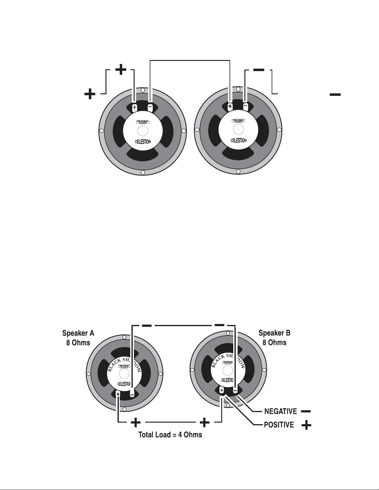
SERIES
to the Positive side of Speaker B
POSITIVE
When you wire ( hook-up ) speakers in series, the speakers resistance ( as measured in ohms ) is additive - i.e.
putting two 8 ohm speakers in series results in a 16 ohm load.
=
H
S
H
S
A
K
C
A
L
B
D
O
W
Speaker A = 8 Ohms
SERIES:
Connect the Negative side of Speaker A
L
B
Speaker B = 8 Ohms
A
K
C
A
D
O
W
NEGATIVE =
PARALLEL
When wiring in parallel, the resistance of the speakers decreases. Two 8 ohm speakers wired in ( hooked-up )
Parallel results in a 4 ohm load. It’s easy to calculate the eect of a resistive load when all the speakers are
all the same resistance. It is really not suggested to wire dierent resistive load values in Parallel ( 8 and 4, 16
and 8 etc. ) The formula for figuring the total impedance in Parallel is the multiplication of the two loads divided
by the sum of the two loads - i.e. putting two 8 ohm speakers in Parallel results in a 4 ohm load. Connect the
Positive side of Speaker A to the Positive side of Speaker B - Connect the Negative side of Speaker A to the
Negative side of Speaker B.
PAGE 24
Page 28
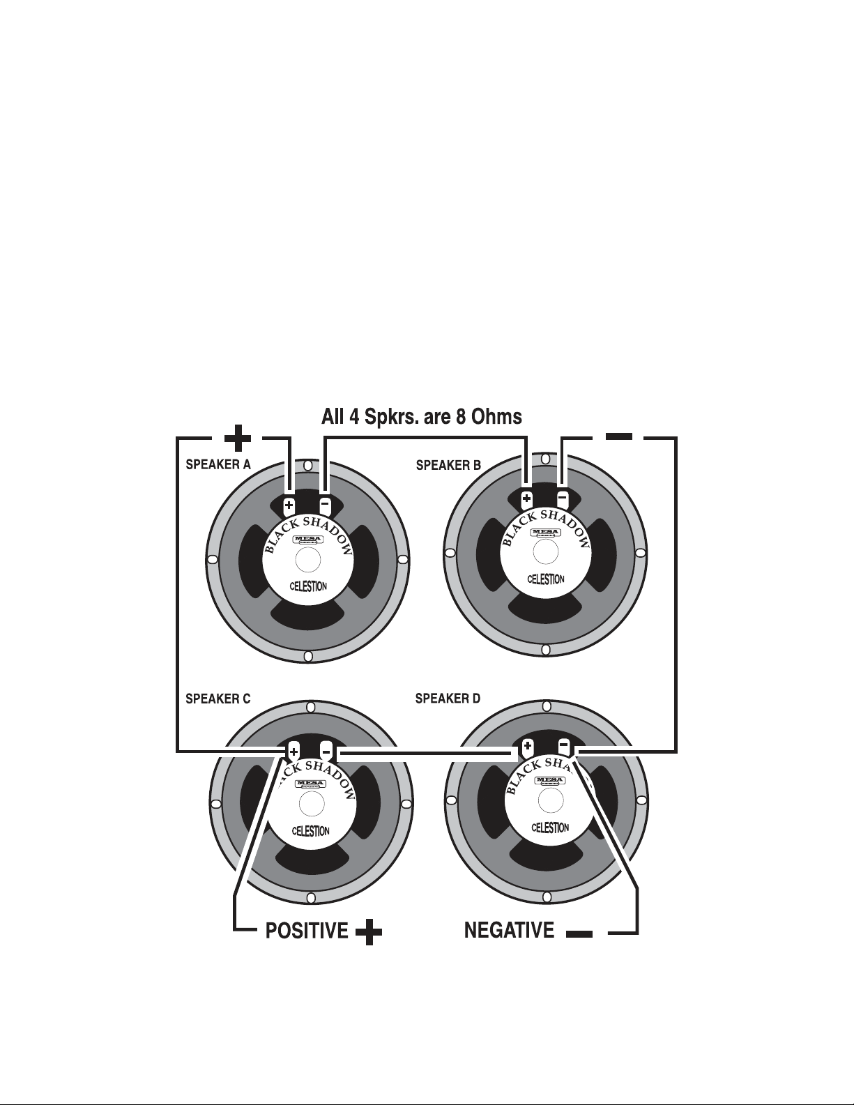
COMBINATION OF SERIES & PARALLEL
This is really just two sets of series wired speakers connected in Parallel. This is how you maintain a consistent
load with multiple speakers. The importance of this is more evident when you have more than one cabinet
to connect to your amplifier. This is when you need to figure out the loads and how to wire them up without
applying too low of a resistance on the amplifier.
Simply connect the Positive side of Speaker A to the Positive side of Speaker C.
Connect the Negative side of Speaker A to the Positive side of Speaker B. Next, connect the Negative side of
Speaker C to the Positive side of Speaker D.
And lastly, connect the Negative side of Speaker B to the Negative side of Speaker D.
4 Eight ( 8 ) Ohm speakers wired in series Parallel = a Total Load of 8 Ohms.
PAGE 25
Page 29
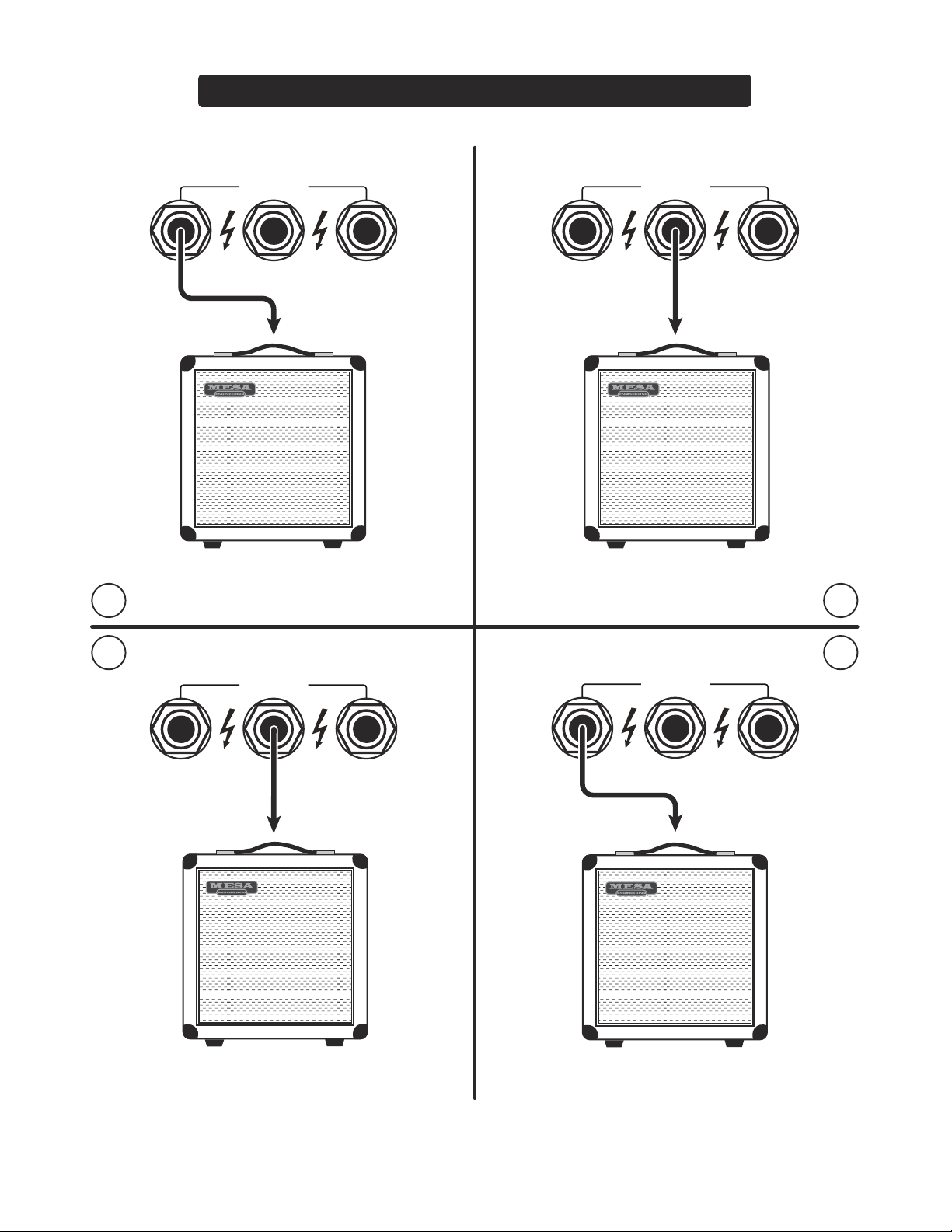
WIRING SCHEMES...Amplifier to Speaker Cabinets
SPEAKERS
8 OHM 4 OHM 4 OHM
1 2
8 Ohm Cabinet
8 OHM 4 OHM 4 OHM
SPEAKERS
4 Ohm Cabinet
3 4
SPEAKERS
8 OHM 4 OHM 4 OHM
8 Ohm Cabinet
SAFE MISMATCH
8 OHM 4 OHM 4 OHM
SPEAKERS
16 Ohm Cabinet
SAFE MISMATCH
PAGE 26
Page 30
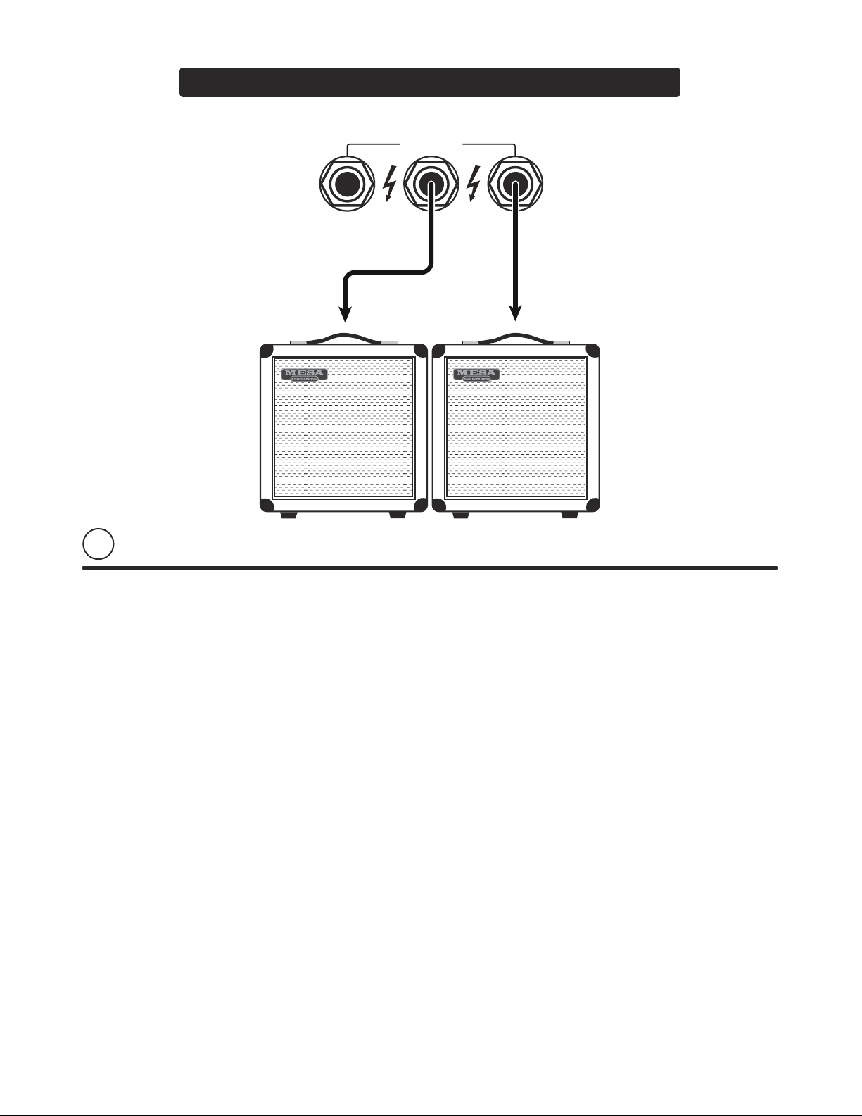
WIRING SCHEMES...Amplifier to Speaker Cabinets
SPEAKERS
8 OHM 4 OHM 4 OHM
5
8 Ohm Cabinet 8 Ohm Cabinet
PAGE 27
Page 31
PLAYER NOTES AND REMINDERS
PAGE 28
Page 32
BEFORE CHANGING TUBES FLIP POWER & STANDBY SWITCH TO OFF
FOR CUSTOMER SUPPORT, PLEASE CALL 707-778-6565 MONDAY-THURSDAY 9-5 PST, OR EMAIL US AT [email protected]
BADLANDER™ 25
TUBE REPLACEMENT DIAGRAM
FRONT OF CHASSIS
5 x 12AX7
12AX7
V5
2 X EL84
EL84
V6
EL84
12AX7
V2
12AX7
V4
V7
INPUT JACK
12AX7
V1
12AX7
V3
PAGE 29
PREAMP TUBES
V1A • 1ST GAIN STAGE ALL MODES
V1B • 2ND GAIN STAGE CRUNCH AND CRUSH
V4A • EFFECTS LOOP SEND
V4B • EFFECTS LOOP RETURN
POWER TUBES
25W • V6 & V7 PENTODE
10W • V6 & V7 TRIODE
V2A/B • TONE STACK DRIVER ALL MODES
V5A/B • DRIVER/PHASE INVERTER
V3A • 3RD GAIN STAGE CRUSH MODE
V3B • 2ND GAIN STAGE CLEAN MODE, 3RD
GAIN STAGE CRUNCH MODE, 4TH GAIN
STAGE CRUSH MODE
TO MAINTAIN WARRANTY, USE MESA/BOOGIE® TUBES WHEN REPLACEMENT IS NECESSARY
Page 33
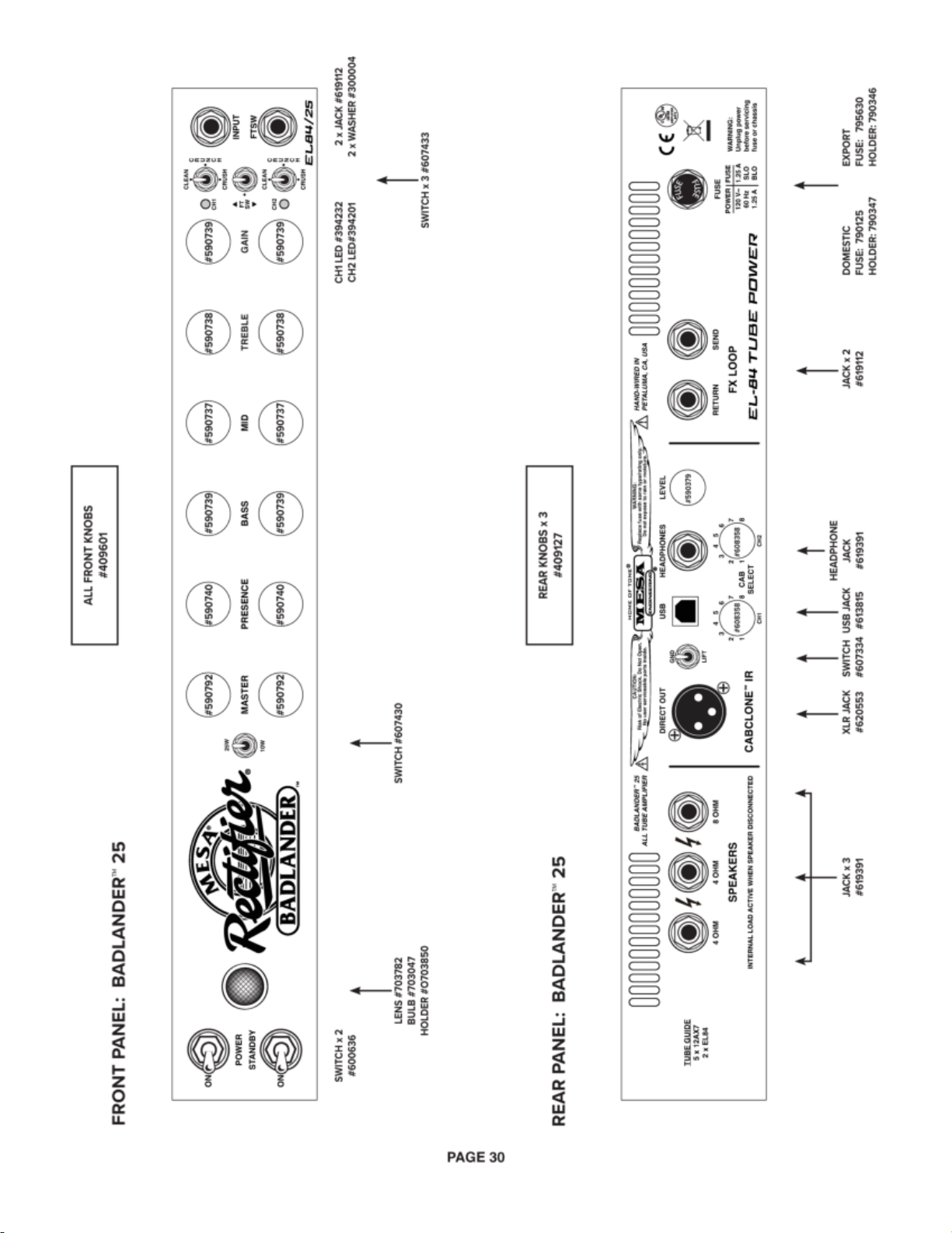
Page 34
Page 35
ank you for trusting MESA/Boogie® to be your
amplier company and we wish you many years of
toneful enjoyment from this handcrafted instrument.
Page 36

1317 Ross Street, Petaluma, CA 94954 USA • (707) 778-6565 • www.mesaboogie.com
23/03/01
 Loading...