

Page 1
M-Series® Mag Meter
Models M2000 and M5000
Field Verication Device
IOM-833-01 (8-11)
IMPORTANT:
This manual contains important information.
READ AND KEEP FOR REFERENCE.
User Guide
Page 2

Field Verication Device
Page ii
8-11
Page 3

User Guide
CONTENTS
Disclaimer ................................................................................................................................................. 5
Questions or Service Assistance .............................................................................................................. 5
Product Identication Information ......................................................................................................... 5
Terminology ............................................................................................................................................. 5
About the Field Verication Device ........................................................................................................ 5
Field Verication Device Functions ......................................................................................................... 6
Verication Device Kit Components .......................................................................................................6
Cable Connections ....................................................................................................................................7
Cable Harness ......................................................................................................................................................... 7
Power Connector ......................................................................................................................................................... 7
USB Connector ............................................................................................................................................................ 7
M2000 ...................................................................................................................................................................... 8
Opening the Cover ...................................................................................................................................................... 8
Connecting the Cable Harness .................................................................................................................................. 8
M2000 Harness Connections...................................................................................................................................... 9
M5000 ...................................................................................................................................................................... 10
Opening the Cover ...................................................................................................................................................... 10
Connecting the Cable Harness .................................................................................................................................. 10
M5000 Harness Connections...................................................................................................................................... 11
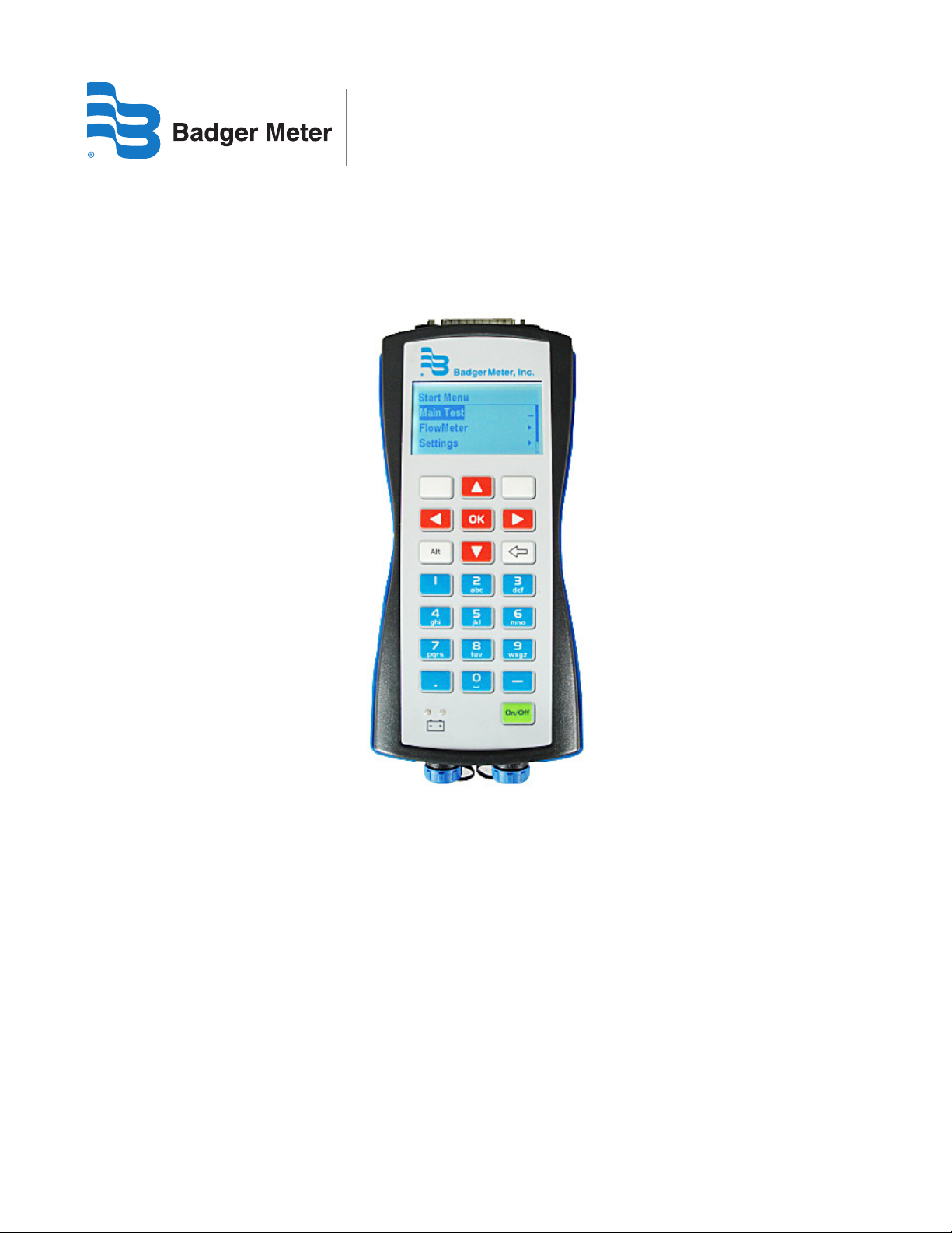
Display and Keypad ................................................................................................................................. 12
Display ..................................................................................................................................................................... 12
Keypad ..................................................................................................................................................................... 12
Power Key ................................................................................................................................................................ 12
Function Keys ......................................................................................................................................................... 12
Alpha-Numeric Keys .............................................................................................................................................. 12
Menu Structure ........................................................................................................................................ 13
Verication Device Settings.................................................................................................................... 14
Time ......................................................................................................................................................................... 15
Contrast ................................................................................................................................................................... 15
Flow Meter Modbus Address ................................................................................................................................. 15
8-11
Page iii
Page 4

Field Verication Device
Verication Device Tests ......................................................................................................................... 16
Main Test ................................................................................................................................................................. 16
Manual Tests ............................................................................................................................................ 17
Amplier Test ......................................................................................................................................................... 18
Detector Test ........................................................................................................................................................... 18
Main Test Fails ......................................................................................................................................................... 19
Meter Identication................................................................................................................................................ 19
About ....................................................................................................................................................................... 20
PC Software .............................................................................................................................................. 21
Installation of the PC Software .............................................................................................................................. 21
Download of the Verication Tests ....................................................................................................................... 21
Print Reports ........................................................................................................................................................... 23
Export Reports ........................................................................................................................................................ 24
Language selection ................................................................................................................................................ 24
Page iv
8-11
Page 5

User Guide
Disclaimer
The user/purchaser is expected to read and understand the information provided in this manual, follow any listed safety
precautions and instructions and keep this manual with the equipment for future reference.
The information in this manual has been carefully checked and is believed to be entirely reliable and consistent with the
product described. However, no responsibility is assumed for inaccuracies, nor does Badger Meter, Inc. assume any liability
arising out of the application and use of the equipment.
Should the equipment be used in a manner not specified by Badger Meter, Inc., the protection provided by the equipment
may be impaired.
Questions or Service Assistance
If you have questions regarding the product or this document contact:
Badger Meter, Inc.
P.O. Box 245036
Milwaukee, WI 53224-9536
Telephone: 414-355-0400, 800-876-3837
Fax: 888-371-5982
Web site: www.badgermeter.com
or call your local Badger Meter representative.
Product Identication Information
Record the product identification numbers from the nameplate.
Modular Mag Meter
Model Number M5000____________________
Serial Number __________________________
Tag Number ____________________________ (if applicable)
Terminology
Throughout this manual, references to “Field Verification Device” may be otherwise be indicated as “Device.”
About the Field Verication Device
Field Verification Device is a portable test device for the Badger Meter M-Series® of electromagnetic flowmeters. The M2000
and the M5000 meters can be tested using this device.
With the Field Verification Device, accurate verification of meter functionality is assured without taking the meter out of the
pipeline ("wet" test) and interrupting functionality. Meter diagnosis and calibration can be performed on site. A "dry" test
(removing the meter and bench testing) can also be performed. The complete verification test consumes approximately 20
minutes and results can be downloaded to a Microsoft Windows® personal computer.
8-11
Page 5
Page 6
Field Verication Device
Field Verication Device Functions
The Device also:
• Determines if the M-Series meter is within one percent of the original factory calibration.
• Verifies the functionality of all of the meter's inputs and outputs.
• Measures electrode resistance and integrity.
• Measures coil resistance and integrity.
• Measures coil insulation resistance.
• Measures current and frequency at previously selected flow rate.
• Evaluates the signal processing functionality.
• Verifies that there is no high-voltage noise disturbing the coil circuit.
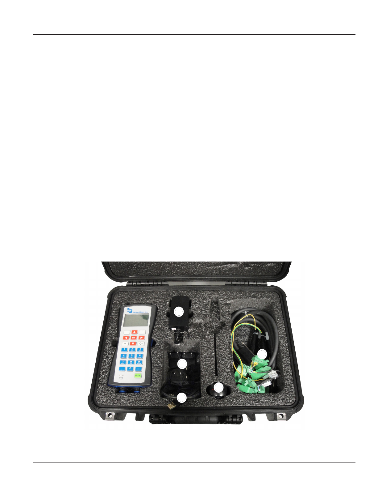
Verication Device Kit Components
The Field Verification Device is packaged in a foam-lined, durable plastic case and includes the following components.
1. One (1) Verication Device +5 VAC, 3.0A power adapter
2. Four (4) AC power conversion connectors
3. One (1) USB PC data cable
4. One (1) DC power adapter
5. Two (2) Verication cable harnesses: one for the M2000 and one for the M5000
1
2
4
3
5
Page 6
Figure 1: Kit Components
8-11
Page 7
User Guide
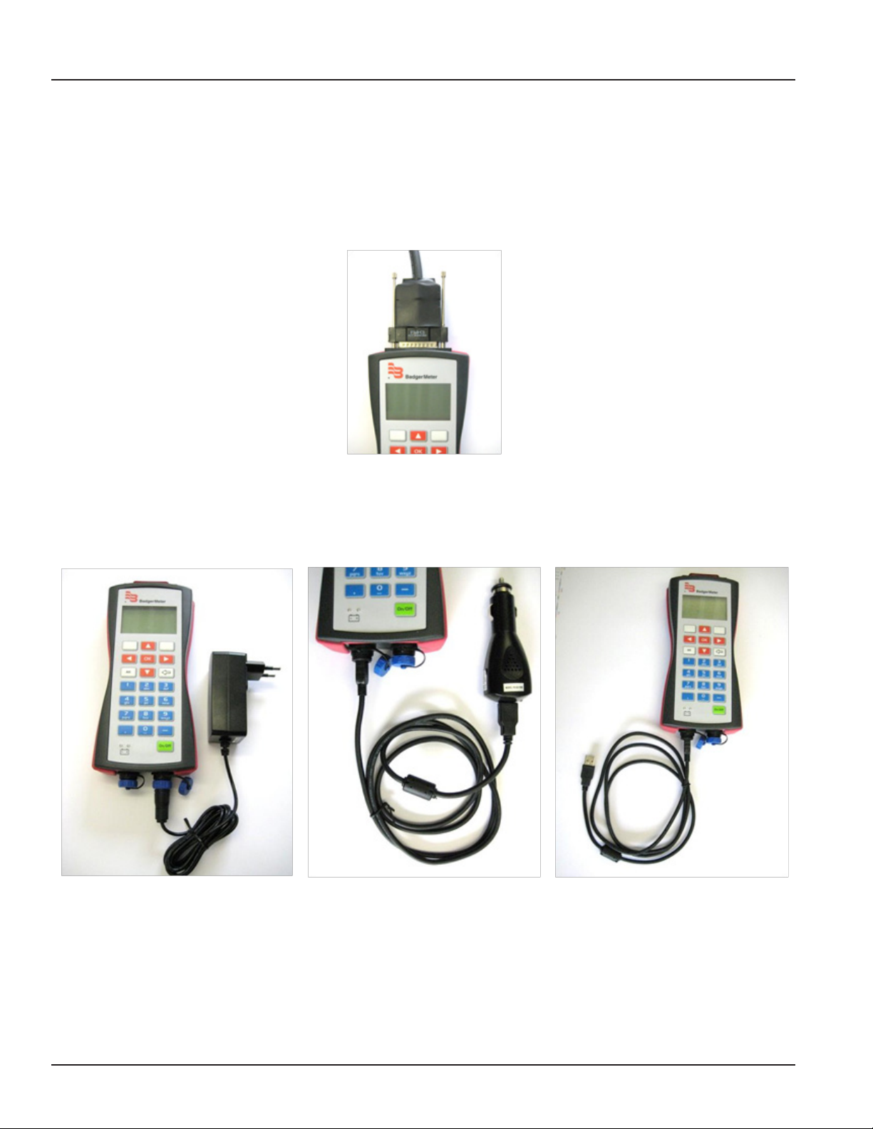
Cable Connections
Cable Harness
The cable harnesses are tagged with either M2000 or M5000 on the outer harness wire cover so the user can differentiate
between the two.
Connect the 25-pin connector of the corresponding cable harness to the top of the Verification Device and secure it with the
two screws on the left and right.
Figure 2: 25-Pin Connection
Power Connector
The Verification Device is a bettery powered unit. Before using the Verification Device, make sure it is fully charged by
connecting it to either the AC or DC power adapter.
AC Power Adapter
Car Charger (DC Power) USB to PC (DC Power)
Figure 3: Power and PC Connections
USB Connector
The USB connector is used for either the DC power adapter or for downloading the test information to a PC.
8-11
Page 7
Page 8
Field Verication Device
M2000
Disconnect the power to the amplifier before connecting the cable harness of the Verification Device.
Opening the Cover
1. Using a ¼ inch slotted screwdriver, remove the two right-hand screws from the front of the amplier.
2. Loosen the two left-hand screws until the screw heads protrude above the surface of the amplier door.
3. Open the amplier door from right side to left.
Connecting the Cable Harness
The individual connector wires are labeled as to where each connector is to be connected onto the internal circuit board of
the amplifier. A connection instruction label has been placed inside the amplifier for reference.
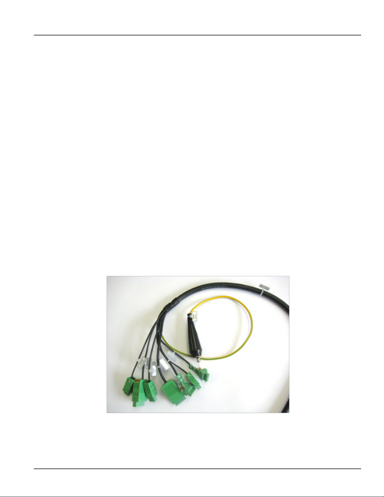
On the M2000 cable harness, the following connectors are tagged:
• Out A B RS232 (7-pin connector)
• Output C D Input (7-pin connector)
• Current Loop (2-pin connector)
• Detector Electrode (6=pin connector)
• Detector Coil (3-pin connector)
• Amplifier Electrodes (6-pin connector)
• Amplifier Coil (3 Pins)
• Detector Ground (alligator clip)
Figure 4: M2000 Wire Harness Connectors
Note: Refer to "M2000 Wire Harness Circuit Board Connectors" on page 9 for the designated circuit board
connections.
Page 8
8-11
Page 9

M2000 Harness Connections
BA2000-22MID
L N PE
JP1
JP2
COMMUNICATION
DISPLAY
CSC2C1
E1
ES
E2
RS
EP
ES
15
16
1
2
3
4
5
6
7
8
9
10
11
12
13
14
Output 1 & 2 / RS232
Output 3 & 4 / Input
Analog Output
Amplifier Coil
Amplifier Electrode
Detector Electrode
Detector Coil
Detector Ground
1. Clip the alligator clip labeled Detector Ground to either of the hex nuts mounted on top of the meter anges.
2. Plug the connector labeled Amplier Electrode into the circuit board connector labeled E1, ES, E2, RS, EP, ES.
3. Plug the Amplier Coil Output into the circuit board connector labeled CS, C2, C1.
4. Plug the Output 1 & 2/ RS232 into the board output connector labeled 1 to 7.
5. Plug the Output 3 & 4 / Input into the board output connector labeled 1 to 14.
6. Plug the Analog Output connector into the board connector labeled 15 and 16 in connector row of
COMMUNICATION / Analog Out on the right side.
7. Connect the harness wire connector labeled Detector Electrode to the 6-wire connector from the detector.
8. Connect the harness wire connector labeled Detector Coil to the 3-wire connector from the detector.
User Guide
8-11
Figure 5: M2000 Wire Harness Circuit Board Connectors
Figure 6: M2000 Detector Connections
Page 9
Page 10

Field Verication Device
M5000
Opening the Cover
1. Using a ¼ inch slotted screwdriver, remove the two top screws from the front of the amplier.
2. Loosen the two bottom screws until the screw heads protrude above the surface of the amplier door.
3. Open the amplier door from top to bottom.
Connecting the Cable Harness
The individual connector wires are labeled as to where each connector is to be connected onto the internal circuit board of
the amplifier. A connection instruction label has been placed inside the amplifier for reference.
On an M5000 cable harness are following connectors:
• RS232 (4-pin connector)
• Output A (2-pin connector)
• Output B (2-pin connector)
• Output C (2-pin connector)
• Output D (2-pin connector)
• Detector Electrode (5-pin connector)
• Detector Coil (2-pin connector)
• Amplifier Electrode (5-pin connector)
• Amplifier Coil Output (2-pin connector)
• Detector Ground (alligator clip)
Figure 7: M5000 Wire Harness Connectors
Note: Refer to "M5000 Harness Connections" on page 11 for the designated circuit board connections.
Page 10
8-11
Page 11

M5000 Harness Connections
Detector Electrode
Detector Coil
Detector Ground
1. Clip the alligator clip labeled Detector Ground to either of the hex nuts mounted on top of the meter anges.
2. Plug the connector labeled Amplier Electrode into the circuit board connector labeled "E1, ┴, E2, ┴, EP.
3. Plug the Amplier Coil Output into the circuit board connector labeled C1, C2.
4. Plug the Output 1 into the board output connector labeled Out1.
5. Plug the Output 2 into the board output connector labeled Out2
6. Plug the Output 3 into the board output connector labeled Out3.
7. Plug the Output 4 into the board output connector labeled Out4.
8. Plug the RS232 into the board output connector labeled RS232.
9. Connect the harness wire connector labeled Detector Electrode to the 5-wire connector from the detector.
10. Connect the harness wire connector labeled Detector Coil to the 2-wire connector from the detector.
User Guide
Figure 8: M5000 Wire Harness Circuit Board Connectors
Figure 9: M5000 Detector Connections
8-11
Page 11
Page 12

Field Verication Device
Display and Keypad
Display
The display is a backlit LCD and displays the current date and time, percent of battery charge and menu indications.
Keypad
The keypad consists of 9 function keys, 12 numeric keys and the On/Off key.
D-25 Harness Connector
Display
Function Keys
Alpha/Numeric Keys
Power Key
AC Power Connector
USB Connector
Figure 10: Verication Device Functions
Power Key
The On/Off power key on the lower right applies or removes power to the Device.
Function Keys
The two (2) top soft keys on the left and right side of the up arrow key provide menu access, wet or dry detector selection.
The up, down, left and right arrow keys provide menu navigation.
The OK key confirms a menu selection.
The Alt key provides no function.
The outlined left arrow is the back or delete key.
Alpha-Numeric Keys
The primary purpose of the alpha-numeric keys is for entering the serial number of a meter if it is not automatically
recognized by the internal firmware or external software. They are also used for Test ID entry.
Page 12
8-11
Page 13

Menu Structure
Refer to the following chart when navigating the Verification Device menus.
User Guide
8-11
Page 13
Page 14

Field Verication Device
Verication Device Settings
Press the On/Off button on the Device and wait for the SelfTest to complete. This takes a few seconds.
After the SelfTest, the display shows date, time, battery capacity and firmware version. Check to make sure the date and time
are correct because the test reports are stored and printed with this data.
When the Start Menu appears, press the upper left function key.
Language
1. Select StartMenu > Menu User > Settings > Misc > Language using the upper right function key.
2. Select the appropriate language. (The default language is English.)
Date
1. Select StartMenu > Settings > Misc > Date.
2. Edit the day, month and year in the edit box by using the numeric keypad. Use the right arrow key to move the
cursor.
3. Conrm the new date with the upper right function key.
Page 14
8-11
Page 15

User Guide
Time
1. Select StartMenu > Settings > Misc > Time.
2. Edit the hour and minutes in the edit box by using the numeric keypad. Use the right arrow key to move the cursor.
3. Conrm the new date with the upper right function key..
Contrast
Adjust the contrast of the display via the function keys (arrows) and save the adjustment with Yes .
Flow Meter Modbus Address
1. Select StartMenu > Settings > FM Modbus Address.
2. Edit the Address in the edit box by using the numeric keypad. Use the Delete arrow key to remove the last number
position.
3. Press the upper right function key to conrm the new address.
4. Be sure that the ow meter is programmed with the same modbus address or communication will fail. The default
address is 1.
8-11
Page 15
Page 16

Field Verication Device
Verication Device Tests
Main Test
The main test is the standard process for meter testing. The result of this test is automatically stored in the memory of the
Veriification Device and can be downloaded to the PC program.
Peform the following steps:
1. Switch o the ow meter and connect the specic wire harness to the amplier circuit board
2. Connect the male D-25 connector of the harness to the corresponding female connector on the Verication Device.
3. Switch on the owmeter to be sure that the meter is not in the programming mode when the test is started.
4. Press the On/O button on the Device and wait for the SelfTest to complete.
5. When the Start Menu appears in the display, press the upper left function key.
6. When the Main Test option is highlighted, press the OK button.
7. Press the appropriate numbers on the numeric keypad for the Test ID and press OK. The Test ID is a value which can
be used as a customer tag.
8. Select Dry or Wet based on the inside condition of the detector tube. This selection has inuence on the test results
of the electrode measurement.
Page 16
8-11
Page 17

User Guide
9. The testing is completed automatically in 10 steps. During the test the ow meter shows Testing in progress on the
display.
10. The result is Passed or Failed.
11. If the test Failed, press the function key View Report on the upper left to see the results. See the example below.
Manual Tests
The result of the manual tests are not stored in the memory of the Veriification Device and cannot be downloaded to the PC
program.
1. Switch o the ow meter and connect the specic wire harness to the amplier circuit board
2. Connect the male D-25 connector of the harness to the corresponding female connector on the Verication Device.
3. Switch on the owmeter and be sure that the meter is not in the programing mode when the test is started.
4. Press the On/O button on the Device and wait for the SelfTest to complete.
5. When the Start Menu appears in the display, press the upper left function key.
6. Select the menu Flow Meter and press the OK button.
8-11
Page 17
Page 18

Field Verication Device
Amplier Test
• Detector Current
• The current [A] and excitation frequency [Hz] are measured
• Analog Input
• Amplification and linearity is measured [div/V]
• Analog Output
• Offset and linearity is measured [mA]
• Inputs/Outputs
• The In- and Ouput function are tested as well as output frequency [Hz]
• Empty Pipe
Detector Test
• Coil Resistance
• Measures the resistance of the coils [Ohm]
• Electrode Impedance
• Measures the impedance of the 3 electrodes (measuring and empty pipe) in [Ohm]
• Isolation
• Measures the resistance of the coils against ground [Ohm]
Page 18
8-11
Page 19

Main Test Fails
Shows the test result of the last Main Test.
Meter Identication
User Guide
The menu displays information about the connected flow meter.
• Product name
• Serial number
• Firmware name and Version
• Compilation date
• Otp Boot Checksum
• Flash Os Checksum
8-11
Page 19
Page 20

Field Verication Device
About
Information about the Verification Device
• Serial number
• Version
• Compilation date
• FlashOsChecksum
• MCU Revision
• Date of last detector current calibration
• Date of last coils resistance calibration
• Date of last analog output calibration
• Date of last analog input calibration
Page 20
8-11
Page 21

User Guide
PC Software
Installation of the PC Software
Insert the software CD, open setup.exe and follow the instructions. An icon on the Desktop will be installed named
Verification Device.
Download of the Verication Tests
1. Start the PC program by clicking the Verication Device icon on your desktop.
2. Connect the Verication Device via the USB cable to the PC and switch the device On. The display on the device
shows USB Mass Storage.
3. The following PC window will be opened automatically. Select the device and click OK. If the window will not open
click FILE and OPEN (Ctrl+O) in the upper task bar.
4. The measurements automatically download to the PC. You will be asked if the measurments which are on the
Verication Device should be deleted or not.
YES
NO
8-11
Page 21
Page 22

Field Verication Device
5. The downloaded measurements are displayed on the left side of the window.
6. Select the new measurements and enter the following information for each test. Customer tag is already given by
entering the Test ID during the testing with the Verication Device. Click Save changes to save the entries.
Page 22
8-11
Page 23

Print Reports
1. Select the measurment which you want to print.
2. Click File and Print.
3. A preview window is shown:
User Guide
4. Click the printer symbol.
8-11
Page 23
Page 24

Export Reports
1. Select Export all... for all or Export selected... for exporting one measurement.
2. Save the data in “CSV” format to be imported to MS Excel®.
Language selection
1. Select Tools and Options.
2. The Options menu opens. Select a Language. (The default is English.)
M-Series is a registered trademark of Badger Meter, Inc.
Other trademarks appearing in this document are the property of their respective entities.
© 2011 Badger Meter, Inc. All rights reserved.
Due to continuous research, product improvements and
enhancements, Badger Meter reserves the right to change
product or system specications without notice, except to the
extent an outstanding contractual obligation exists.
Badger Meter | P.O. Box 245036, Milwaukee, Wisconsin 53224-9536
800-876-3837 | infocentral@badgermeter.com | www.badgermeter.com
 Loading...