

Page 1
M-Series® M3000
Electromagnetic Flow Meter
DESCRIPTION
The innovative design of the Badger Meter M-Series M3000 meter
represents the next generation of electromagnetic flow meter
technology. Incorporating the latest developments in micro
processing signal conditioning the advanced design of the M3000
allows an accuracy of better than ± 0.25% with a flow range of
300:1. Targeted to a variety of industrial and municipal applications,
the M3000 is virtually unaffected by density, temperature, pressure,
and viscosity changes and provides an accurate and reliable
long term metering solution. This meter complies with ANSI/NSF
Standard 61, Annex G.
OPERATION
The operating principle of the electromagnetic flow meter is based
on Faraday’s law of magnetic induction: The voltage induced across
any conductor, as it moves at right angles through a magnetic
field, is proportional to the velocity of that conductor. The voltage
induced within the fluid is measured by two diametrically opposed
internally mounted electrodes. The induced signal voltage is
proportional to the product of the magnetic flux density, the
distance between the electrodes and the average flow velocity of
the fluid.
ELECTRODES
When looking from the end of the meter into the inside bore,
the two measuring electrodes are positioned at three o’clock and
nine o’clock. As a conductive fluid flows through the magnetic
field, a voltage is induced across the electrodes. This voltage
is proportional to the average flow velocity of the fluid and is
measured by the two electrodes. This induced voltage is then
amplified and processed digitally by the converter to produce an
accurate analog or digital signal. The signal can then be used to
indicate flow rate and totalization or to communicate to remote
sensors and controllers.
M3000 meters also have an “empty pipe” detection feature. This
is accomplished with a third electrode positioned in the meter
between twelve o’clock and one o’clock. If this electrode is not
covered by fluid for minimum of five seconds, the meter will display
an “empty pipe” condition. When the electrode again becomes
covered with fluid, the error message will disappear and the meter
will continue measuring.
DETECTOR
The flow meter is a stainless steel tube lined with a non-conductive
material. Outside the tube, two DC powered electromagnetic coils
are positioned opposing each other. Perpendicular to these coils,
two electrodes are inserted into the flow tube. Energized coils
create a magnetic field across the whole diameter of the pipe. With
the no moving parts, open flow tube design there is no pressure
lost and practically no maintenance required.
APPLICATION
The M3000 meter is suited for use in applications where indication
of rate and totalization is required. The ability to display flow
parameters locally at the flow meter, or remotely by mounting the
amplifier up to 100 feet away from the detector, provides a versatile
solution for most industrial and municipal flow applications.
Whether the fluid is water or something highly corrosive, very
viscous, contains a moderate amount of solids, or requires special
handling, the meter is able to accurately measure it. Housed in a
Class 1, Division 2, NEMA 4X/6P (IP66/IP67) enclosure, the M3000
design has been tested and approved by Factory Mutual (FM) in
the United States and the Canadian Standards Association (CSA
international) in Canada.
FEATURES
• Sizes 1/4…24 in. (6…600 mm)
• Accuracy of ± 0.25%
• Better than 0.1% repeatability
• Large 4-line by 16-character, back-lit, LCD display
• Digital Signal Processor (DSP) based
• Bi-directional flow sensing and totalization
• Automatic zero point stability
• Measures fluids with as low as 5.0 micromhos/cm conductivity
• Empty pipe detection
• No pressure loss for low operational costs
• Long life, corrosion-resistant liners
• Precise calibration
• NEMA 4X/6P (IP66/IP67) enclosure
• FM approved for Class I, Div 2 hazardous locations
• CE and FCC compliant
• CSA Certified
MAG-DS-00493-EN-06 (August 2018)
Product Data Sheet
Page 2
M-Series® M3000, Electromagnetic Flow Meter
SPECIFICATIONS
Sizes 1/4…24 in. (6…600 mm)
Flow Range 0.10…39.4 ft/s (0.03…12 m/s)
Accuracy ± 0.25% of rate for velocities greater than 1.64 ft/s (0.50 m/s)
Repeatability 0.1% of rate
Power Supply AC or optional 24V DC
Analog Outputs 0…10 mA, 0…20 mA, 4…20 mA (programmable and scalable)
Digital Outputs (2) Open Collector, (programmable – scaled pulse, flow alarm, status, or frequency output) Max. 24V DC, 0.5 W
Frequency Output Open Collector; Max. full scale flow = 10 Khz
Communication RS232C serial, standard ANSI terminal compatible data stream
Pulse Width Open Collector, 5 ms to 1 second (programmable) or automatic 50% duty cycle
Min-Max Flow Alarm Open collector or solid-state relay (programmable, 0 to 100% of flow)
Empty Pipe Detection Field tunable for optimum performance based on specific application
Excitation Frequency Programmable, 3.75 Hz, 7.5 Hz or 15 Hz
Auxiliary Input Max. 24V DC (programmable – positive zero return, external totalizer reset or preset batch start)
Noise Dampening 1 to 30 seconds (programmable)
Low Flow Cutoff 0…100% of full scale (programmable)
Zero-Point Stability Automatic correction
Galvanic Separation 500V
Fluid Conductivity Min. 5.0 micromhos/cm
Fluid Temperature With Meter-Mounted Amplifier:
Ambient Temperature – 4…122° F (–20…50° C)
Relative Humidity Up to 90% non-condensing
Altitude Maximum 6500 ft (2000 m)
Flow Direction Uni-directional or bi-directional
Totalization 3 separate displayable totalizers; 10 digits (programmable – forward, reverse and net)
Units of Measure U.S. gallons, imperial gallons, million gallons per day, cubic feet, cubic meters, liters, oil barrels, pounds, ounces, acre feet
LC Display 4-line by 16-character, alphanumeric, back light
Programming Internal 3-button or external magnetic wand
Field Wiring Entry Ports (3) 1/2" NPT, internal thread
Amplifier Housing Amplifier enclosure and remote junction enclosure: cast aluminum (powder coated paint)
Amplifier Housing
Rating
Detector Pipe Spool
Material
Detector Spool Housing
Material
Electrode Materials Alloy C, 316 stainless steel (standard), gold/platinum plated, tantalum, platinum/rhodium
Liner Material PFA from 1/4…3/8 in. (6…10 mm), PTFE from 1/2…24 in. (15…600 mm), hard rubber from 1…24 in. (25…600 mm),
Flanges Carbon steel or 316 stainless steel (ANSI B16.5 Class 150 RF)
Coil Power Pulsed DC
Pressure Limits Max. 150 psi (10 bar)
Mounting Direct detector mount or remote wall mount, bracket included. For remote mount, max. cable distance = 100 ft (30 m)
Junction Enclosure
Material
Optional Stainless Steel
Grounding Rings
Optional Grounding
Electrodes
Electrical Classification FM approved for Class I, Div 2, Groups A-D; Class II, Div 2, Groups F and G, – CSA Certified
± 0.004 ft/s (± 0.001 m/s) for velocities less than 1.64 ft/s (0.50 m/s)
AC Power Supply: 85…265V AC, 45…65 Hz
Voltage Fluctuation = ± 10% of nominal
Over Voltage = Catagory II
Power Consumption = 20 W
DC Power Supply (optional): 24V DC ± 10% 8 W
Voltage sourced (18V DC) isolated
Max. loop resistance = 750 Ω
(2) AC solid-state relay (programmable – flow alarm or status) Max. 24V D C @ 0.5 A
PFA, PTFE & Halar®: -4…212° F (-20…100° C) @ max. ambient
temperature of 122° F (50° C).
Hard rubber: 32…178° F (0…81° C) @ max. ambient
temperature of 122° F (50° C).
(programmable).
Displays: 3 totalizer values, flow rate, alarm status, output status, error/diagnostic messages
Amplifier enclosure and remote junction enclosure: NEMA 4X/6P (IP66/IP67)
316 stainless steel
Carbon steel, welded, NEMA 4X/6P (IP66/IP67)
Halar from 12…24 in. (300…600 mm)
For remote mounted amplifier option: Cast aluminum, powder-coated paint, NEMA 4X/6P (IP66/IP67)
Meter Size Thickness (of 1 ring)
1/4…10 in. (6…250 mm) 0.135 in. (3.43 mm)
10…24 in. (250…600 mm) 0.187 in. (4.75 mm)
Alloy C, 316 stainless steel, gold/platinum plated, tantalum, or platinum/rhodium
With Remote Amplifier:
PFA, PTFE & Halar: -4…248° F (-20…120° C) @ max. ambient
temperature of 122° F (50° C).
Hard rubber: 32…178° F (0…81° C) @ max. ambient
temperature of 122° F (50° C).
Page 2 August 2018MAG-DS-00493-EN-06
Page 3
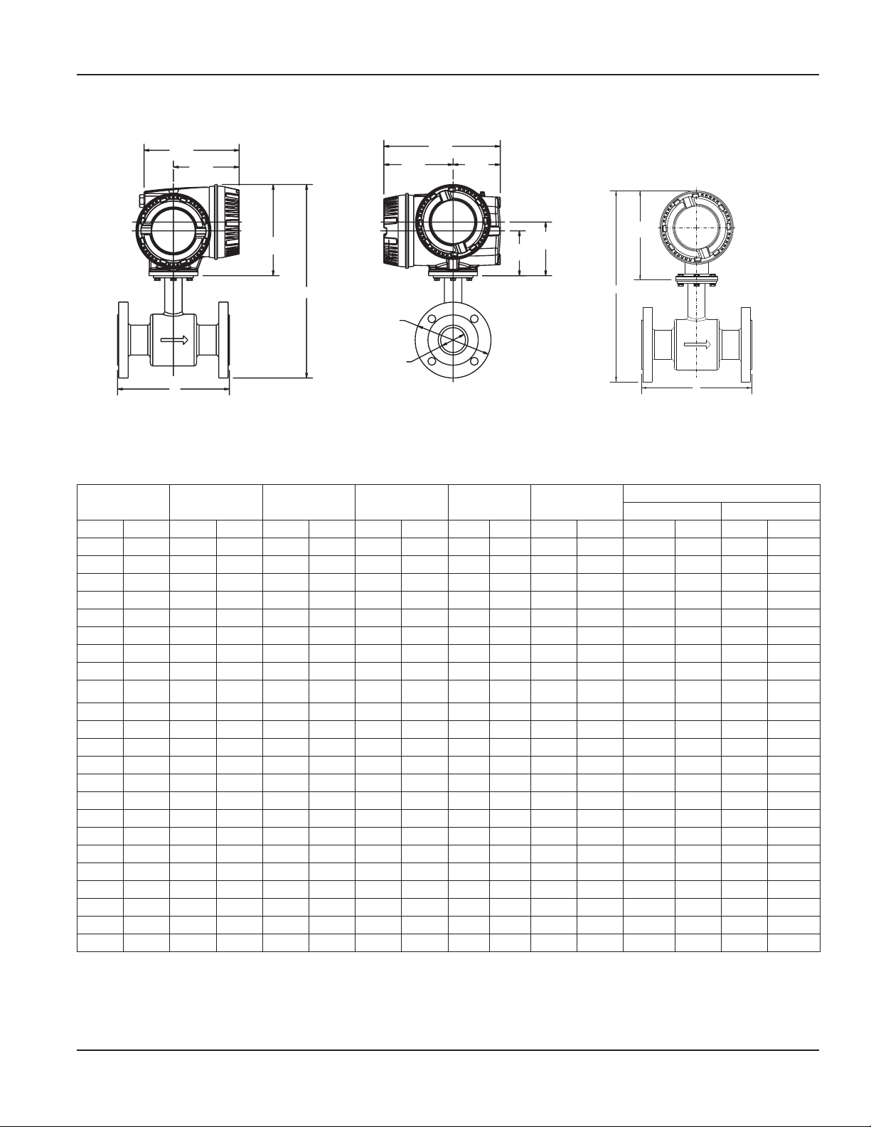
DIMENSIONS
m
Product Data Sheet
5.47"
139mm
9.20"
234mm
3.73"
95mm
3.54"
90mm
4.25"
108m
7.42"
188 mm
B
A
7.52"
191mm
A
5.20"
132mm
7.22"
183mm
B
0 C
SIZE
M3000 Meter Mount M3000 Remote Mount Junction Box on Detector
Size A B C D
Est. Weight
with Amplifier
Flow Range
GPM LPM
inch mm inch mm inch mm inch mm inch mm lb kg min max min max
1/4 6 6.7 170 13.4 342 3.5 89 13.9 351 17 7.7 0.01 5 0.05 20
5/16 8 6.7 170 13.4 342 3.5 89 13.9 351 17 7.7 0.02 10 0.09 36
3/8 10 6.7 170 13.4 342 3.5 89 13.9 351 17 7.7 0.04 15 0.14 57
1/2 15 6.7 170 13.4 342 3.5 89 13.9 351 17 7.7 0.08 34 0.32 127
3/4 20 6.7 170 13.6 347 3.9 99 14 356 17 7.7 0.12 48 0.46 183
1 25 8.9 225 13.8 352 4.3 108 14.2 361 18 8.8 0.21 84 0.79 318
1-1/4 32 8.9 225 14.6 372 4.6 117 15 381 20.3 9.2 0.39 157 1.5 594
1-1/2 40 8.9 225 14.8 376 5.0 127 15.2 386 22 10 0.55 220 2.1 834
2 50 8.9 225 15.3 389 6.0 152 15.7 398 26 11.7 0.94 378 3.6 1431
2-1/2 65 11.0 280 16.5 420 7.0 178 16.9 429 35 15.7 1.63 653 6.2 2471
3 80 11.0 280 16.7 426 7.5 191 17.2 435 38 17.1 2.21 883 8.4 3344
4 100 11.0 280 17.8 452 9.0 229 18.2 461 49 22.1 3.30 1320 12 4997
5 125 15.8 400 19 484 10.0 264 19.4 493 60 27.1 5.29 2115 20 8008
6 150 15.8 400 20 510 11.0 279 20.4 519 71 32.1 7.85 3141 30 11890
8 200 15.8 400 21.9 558 13.5 343 22.9 583 96 43.1 15.69 6278 59 23765
10 250 19.7 500 26.2 677 16.0 406 26.6 676 130 59.1 25.05 10021 95 37934
12 300 19.7 500 28.3 720 19.0 483 28.7 729 219 99.3 33.61 13445 127 50894
14 350 19.7 500 30.2 768 21.0 533 30.7 779 287 130.2 45.75 18300 173 69272
16 400 23.6 590 33.1 842 23.5 597 33.5 851 354 160.9 59.75 23902 226 90477
18 450 23.6 590 34.4 876 25.0 635 34.9 885 409 185.3 75.63 30250 286 114511
20 500 23.6 590 337.6 955 27.5 699 38 964 502 228.3 93.37 37346 353 141371
22 550 23.6 590 39 991 29.5 749 39.4 1000 532 241.3 112.97 45189 428 171059
24 600 23.6 590 41.6 1057 32.0 813 42 1066 561 255.3 134.45 53779 509 203574
Page 3 August 2018 MAG-DS-00493-EN-06
Page 4

M-Series® M3000, Electromagnetic Flow Meter
Control. Manage. Optimize.
M-SERIES is a registered trademark of Badger Meter, Inc. Other trademarks appearing in this document are the property of their respective entities. Due to continuous research,
product improvements and enhancements, Badger Meter reserves the right to change product or system specications without notice, except to the extent an outstanding
contractual obligation exists. © 2018 Badger Meter, Inc. All rights reserved.
www.badgermeter.com
The Americas | Badger Meter | 4545 West Brown Deer Rd | PO Box 245036 | Milwaukee, WI 53224-9536 | 800-876-3837 | 414-355-0400
México | Badger Meter de las Americas, S.A. de C.V. | Pedro Luis Ogazón N°32 | Esq. Angelina N°24 | Colonia Guadalupe Inn | CP 01050 | México, DF | México | +52-55-5662-0882
Europe, Eastern Europe Branch Office (for Poland, Latvia, Lithuania, Estonia, Ukraine, Belarus) | Badger Meter Europe | ul. Korfantego 6 | 44-193 Knurów | Poland | +48-32-236-8787
Europe, Middle East and Africa | Badger Meter Europa GmbH | Nurtinger Str 76 | 72639 Neuffen | Germany | +49-7025-9208-0
Europe, Middle East Branch Office | Badger Meter Europe | PO Box 341442 | Dubai Silicon Oasis, Head Quarter Building, Wing C, Office #C209 | Dubai / UAE | +971-4-371 2503
Slovakia | Badger Meter Slovakia s.r.o. | Racianska 109/B | 831 02 Bratislava, Slovakia | +421-2-44 63 83 01
Asia Pacific | Badger Meter | 80 Marine Parade Rd | 21-06 Parkway Parade | Singapore 449269 | +65-63464836
China | Badger Meter | 7-1202 | 99 Hangzhong Road | Minhang District | Shanghai | China 201101 | +86-21-5763 5412
Switzerland | Badger Meter Swiss AG | Mittelholzerstrasse 8 | 3006 Bern | Switzerland | +41-31-932 01 11 Legacy Document Numbers: ITB-139, ITB-141, ITB-165, ITB-166
 Loading...