

Page 1
M-Series® M2000
Electromagnetic Flow Meter
IOM-175-04-EN (August 2012)
53400-190 Rev. 4
Installation & Operation Manual
Page 2

M-Series® M2000 Electromagnetic Flow Meter
Page ii August 2012
Page 3

Installation & Operation Manual
CONTENTS
SAFETY PRECAUTIONS AND INSTRUCTIONS . . . . . . . . . . . . . . . . . . . . . . . . . . . . . . . . . . . . . .5
SYSTEM DESCRIPTION . . . . . . . . . . . . . . . . . . . . . . . . . . . . . . . . . . . . . . . . . . . . . . . . . . . . .5
UNPACKING AND INSPECTION . . . . . . . . . . . . . . . . . . . . . . . . . . . . . . . . . . . . . . . . . . . . . . .6
Rigging, Lifting and Moving Large Units . . . . . . . . . . . . . . . . . . . . . . . . . . . . . . . . . . . . . . . 6
METER LOCATION, ORIENTATION AND APPLICATIONS . . . . . . . . . . . . . . . . . . . . . . . . . . . . . . . .8
Remote Amplier Outdoor Location . . . . . . . . . . . . . . . . . . . . . . . . . . . . . . . . . . . . . . . . . .8
Pipelines and Fluid Flow. . . . . . . . . . . . . . . . . . . . . . . . . . . . . . . . . . . . . . . . . . . . . . . . . .8
Meter Orientation. . . . . . . . . . . . . . . . . . . . . . . . . . . . . . . . . . . . . . . . . . . . . . . . . . . . . .9
Vertical Placement . . . . . . . . . . . . . . . . . . . . . . . . . . . . . . . . . . . . . . . . . . . . . . . . . . . . .9
Horizontal Placement . . . . . . . . . . . . . . . . . . . . . . . . . . . . . . . . . . . . . . . . . . . . . . . . . . . 9
Straight Pipe Requirements . . . . . . . . . . . . . . . . . . . . . . . . . . . . . . . . . . . . . . . . . . . . . . 10
Pipe Reducer Requirements . . . . . . . . . . . . . . . . . . . . . . . . . . . . . . . . . . . . . . . . . . . . . . 10
Chemical Injection Applications. . . . . . . . . . . . . . . . . . . . . . . . . . . . . . . . . . . . . . . . . . . .11
Partially-Filled Pipe Situations . . . . . . . . . . . . . . . . . . . . . . . . . . . . . . . . . . . . . . . . . . . . . 12
METER GASKETS AND GROUNDING . . . . . . . . . . . . . . . . . . . . . . . . . . . . . . . . . . . . . . . . . . . 13
Meter/Pipeline Connection Gaskets . . . . . . . . . . . . . . . . . . . . . . . . . . . . . . . . . . . . . . . . . 13
Meter Grounding . . . . . . . . . . . . . . . . . . . . . . . . . . . . . . . . . . . . . . . . . . . . . . . . . . . . .13
Conductive Pipe Grounding . . . . . . . . . . . . . . . . . . . . . . . . . . . . . . . . . . . . . . . . . . . . . . 13
Non-Conductive Pipe Grounding . . . . . . . . . . . . . . . . . . . . . . . . . . . . . . . . . . . . . . . . . . . 14
AMPLIFIER MOUNTING CONFIGURATION OPTIONS . . . . . . . . . . . . . . . . . . . . . . . . . . . . . . . . .14
Meter Mount Conguration . . . . . . . . . . . . . . . . . . . . . . . . . . . . . . . . . . . . . . . . . . . . . . 14
Remote Mount Conguration . . . . . . . . . . . . . . . . . . . . . . . . . . . . . . . . . . . . . . . . . . . . . 14
Submersible Option . . . . . . . . . . . . . . . . . . . . . . . . . . . . . . . . . . . . . . . . . . . . . . . . . . . 14
WIRING. . . . . . . . . . . . . . . . . . . . . . . . . . . . . . . . . . . . . . . . . . . . . . . . . . . . . . . . . . . . . .15
Wiring Safety. . . . . . . . . . . . . . . . . . . . . . . . . . . . . . . . . . . . . . . . . . . . . . . . . . . . . . . .15
Opening the M2000 Cover . . . . . . . . . . . . . . . . . . . . . . . . . . . . . . . . . . . . . . . . . . . . . . . 15
Power Connections. . . . . . . . . . . . . . . . . . . . . . . . . . . . . . . . . . . . . . . . . . . . . . . . . . . .15
External Disconnect . . . . . . . . . . . . . . . . . . . . . . . . . . . . . . . . . . . . . . . . . . . . . . . . . . . . . . . . . . . . . 16
AC Power Wiring. . . . . . . . . . . . . . . . . . . . . . . . . . . . . . . . . . . . . . . . . . . . . . . . . . . . . . . . . . . . . . . . 16
Remote Mount Installation . . . . . . . . . . . . . . . . . . . . . . . . . . . . . . . . . . . . . . . . . . . . . . . 16
Mount Bracket to Amplier. . . . . . . . . . . . . . . . . . . . . . . . . . . . . . . . . . . . . . . . . . . . . . . . . . . . . . . . . 16
Wiring Conguration. . . . . . . . . . . . . . . . . . . . . . . . . . . . . . . . . . . . . . . . . . . . . . . . . . . . . . . . . . . . . 16
Wiring for Remote Conguration . . . . . . . . . . . . . . . . . . . . . . . . . . . . . . . . . . . . . . . . . . . . . . . . . . . . . 17
Empty Pipe Detection Considerations . . . . . . . . . . . . . . . . . . . . . . . . . . . . . . . . . . . . . . . . . . . . . . . . . . 17
CONFIGURING INPUT/OUTPUT I/O . . . . . . . . . . . . . . . . . . . . . . . . . . . . . . . . . . . . . . . . . . .18
Analog Output Wiring Diagram . . . . . . . . . . . . . . . . . . . . . . . . . . . . . . . . . . . . . . . . . . . . . . . . . . . . . . 19
Digital Output Wiring Diagrams. . . . . . . . . . . . . . . . . . . . . . . . . . . . . . . . . . . . . . . . . . . . . . . . . . . . . . 20
Digital Input Wiring Diagram. . . . . . . . . . . . . . . . . . . . . . . . . . . . . . . . . . . . . . . . . . . . . . . . . . . . . . . . 20
PROGRAMMING THE M2000 . . . . . . . . . . . . . . . . . . . . . . . . . . . . . . . . . . . . . . . . . . . . . . . . 21
Displays . . . . . . . . . . . . . . . . . . . . . . . . . . . . . . . . . . . . . . . . . . . . . . . . . . . . . . . . . . . 21
Menu Selection Display . . . . . . . . . . . . . . . . . . . . . . . . . . . . . . . . . . . . . . . . . . . . . . . . . . . . . . . . . . . 21
Numeric Entry Display . . . . . . . . . . . . . . . . . . . . . . . . . . . . . . . . . . . . . . . . . . . . . . . . . . . . . . . . . . . . 21
Function Buttons . . . . . . . . . . . . . . . . . . . . . . . . . . . . . . . . . . . . . . . . . . . . . . . . . . . . . 22
Page iii August 2012
Page 4

M-Series® M2000 Electromagnetic Flow Meter
SECURITY . . . . . . . . . . . . . . . . . . . . . . . . . . . . . . . . . . . . . . . . . . . . . . . . . . . . . . . . . . . . 24
Setting the Administration PIN . . . . . . . . . . . . . . . . . . . . . . . . . . . . . . . . . . . . . . . . . . . . 24
Setting the Service PIN . . . . . . . . . . . . . . . . . . . . . . . . . . . . . . . . . . . . . . . . . . . . . . . . . 24
Setting the User PIN . . . . . . . . . . . . . . . . . . . . . . . . . . . . . . . . . . . . . . . . . . . . . . . . . . . 24
Entering Your Personal Identication Number (PIN) . . . . . . . . . . . . . . . . . . . . . . . . . . . . . . . 25
SETTING UP THE M2000 WITH QUICK SETUP . . . . . . . . . . . . . . . . . . . . . . . . . . . . . . . . . . . . . 26
QUICK REFERENCE . . . . . . . . . . . . . . . . . . . . . . . . . . . . . . . . . . . . . . . . . . . . . . . . . . . . . . 28
USING THE M2000 MAIN MENU PROGRAMMING OPTIONS . . . . . . . . . . . . . . . . . . . . . . . . . . . . 29
ADE INTERFACE . . . . . . . . . . . . . . . . . . . . . . . . . . . . . . . . . . . . . . . . . . . . . . . . . . . . . . . . 52
STORE / RESTORE FEATURE . . . . . . . . . . . . . . . . . . . . . . . . . . . . . . . . . . . . . . . . . . . . . . . . .54
DATA LOGGING FEATURE . . . . . . . . . . . . . . . . . . . . . . . . . . . . . . . . . . . . . . . . . . . . . . . . . . 54
MAINTENANCE. . . . . . . . . . . . . . . . . . . . . . . . . . . . . . . . . . . . . . . . . . . . . . . . . . . . . . . . .55
Cleaning the Flow Tube and Electrode. . . . . . . . . . . . . . . . . . . . . . . . . . . . . . . . . . . . . . . .55
Replacing the Fuse . . . . . . . . . . . . . . . . . . . . . . . . . . . . . . . . . . . . . . . . . . . . . . . . . . . . 55
Replacing the Circuit Board. . . . . . . . . . . . . . . . . . . . . . . . . . . . . . . . . . . . . . . . . . . . . . .55
TROUBLESHOOTING . . . . . . . . . . . . . . . . . . . . . . . . . . . . . . . . . . . . . . . . . . . . . . . . . . . . . 56
Page iv August 2012
Page 5
Installation & Operation Manual
SAFETY PRECAUTIONS AND INSTRUCTIONS
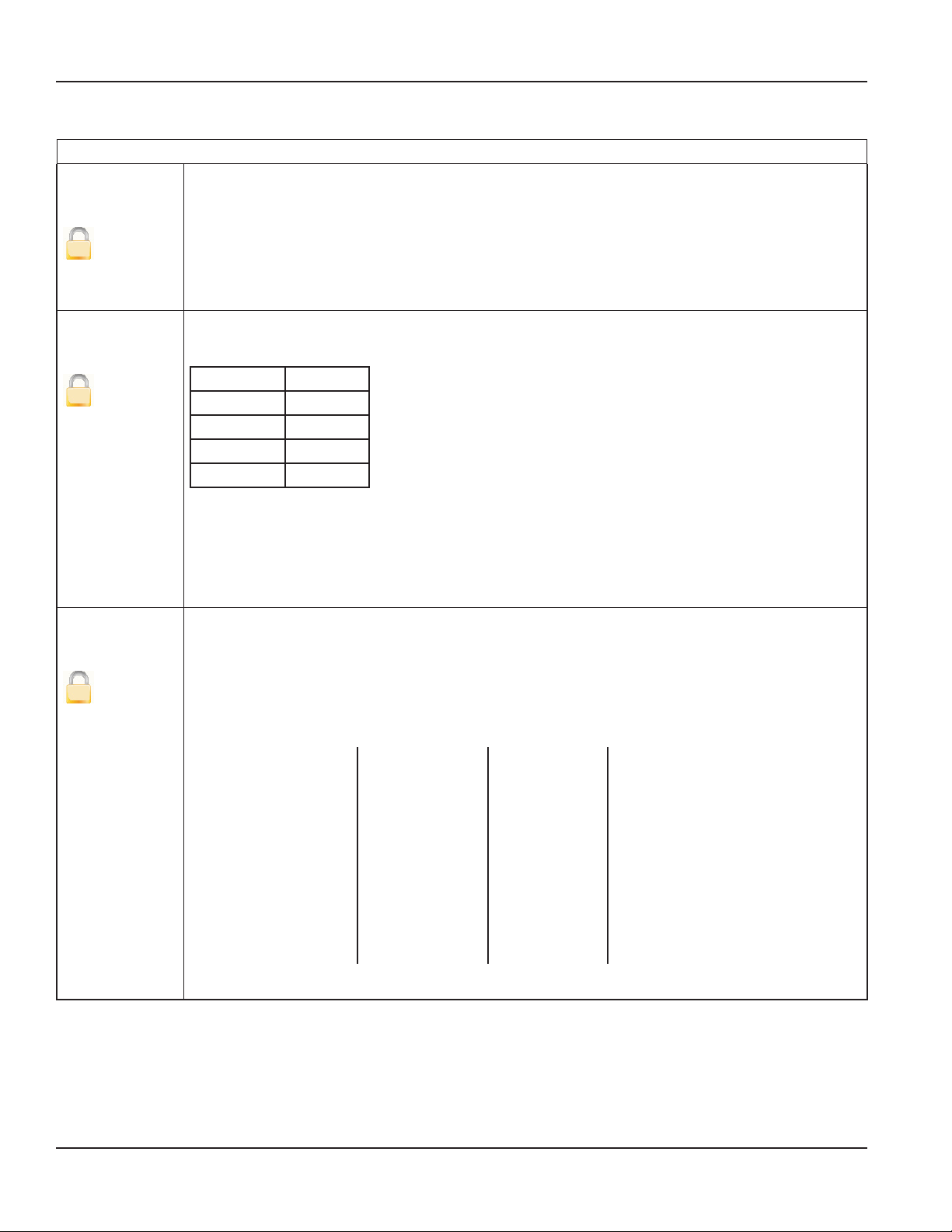
Some procedures in this manual require special safety considerations. In such cases, the text is emphasized with the following
symbols:
Symbol Explanation
Warning indicates the potential for severe personal injury, death or substantial property damage.
Comply with the instructions and proceed with care.
Caution indicates the potential for minor personal injury or property damage. Comply with the
instructions and proceed with care.
SYSTEM DESCRIPTION
The Badger Meter M-Series® model M2000 electromagnetic flow meter is intended for fluid metering in most industries
including water, wastewater, food and beverage, pharmaceutical and chemical.
The basic components of an electromagnetic flow meter are:
• The detector, which includes the flow tube, isolating liner and measuring electrodes.
• The amplifier, which is the electronic device responsible for the signal processing, flow calculation, display and output
signals.
Amplifier
®
Figure 1: Amplifier and Detector
The construction materials of the wetted parts (liner and electrodes) should be appropriate for the specifications on the
intended type of service. We recommend that you review all of the compatibilities consistent with the specifications.
Each meter is factory tested and calibrated. A calibration certificate is included with each meter.
Detector
Page 5 August 2012
Page 6
®
M-Series® M2000 Electromagnetic Flow Meter
UNPACKING AND INSPECTION
Follow these guidelines when unpacking the M-Series equipment.
• If a shipping container shows any sign of damage, have the shipper present when you unpack the meter.
• Follow all unpacking, lifting and moving instructions associated with the shipping container.
• Open the container and remove all packing materials. Store the shipping container and packing
materials in the event the unit needs to be shipped for service.
• Verify that the shipment matches the packing list and your order form.
• Inspect the meter for any signs of shipping damage, scratches, or loose or broken parts.
OTE:N If the unit was damaged in transit, it is your responsibility to request an inspection report from the carrier within 48
hours. You must then file a claim with the carrier and contact Badger Meter for appropriate repairs or replacement.
• All detectors with polytetrafluoroethylene (PTFE) liners are shipped with a liner protector on each end to maintain
proper form of the PTFE material during shipping and storage.
OTE:N Do not remove the liner protectors until you are ready to install.
• Storage: If the meter is to be stored, place it in its original container in a dry, sheltered location. Storage temperature
ranges are: –40…160° F (–40…70° C).
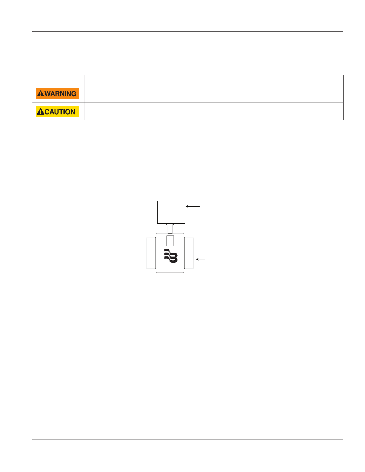
Rigging, Lifting and Moving Large Units
When rigging, lifting or moving large units, follow these guidelines:
• DO NOT lift or move a meter by its amplifier, junction box or cables.
• Use a crane rigged with soft straps to lift and move meters with flow tubes that are between two inches and eight
inches (50 mm and 200 mm). Place the straps around the detector body, between the flanges, on each side of the
detector.
• Use the lifting lugs when lifting meter flow tubes that are 10 inches (250 mm) in diameter or larger.
®
Place straps between flanges. Use lifting lugs with 10-inch or larger meters.
Figure 2: Rigging Large Units
Page 6 August 2012
Page 7
Installation & Operation Manual
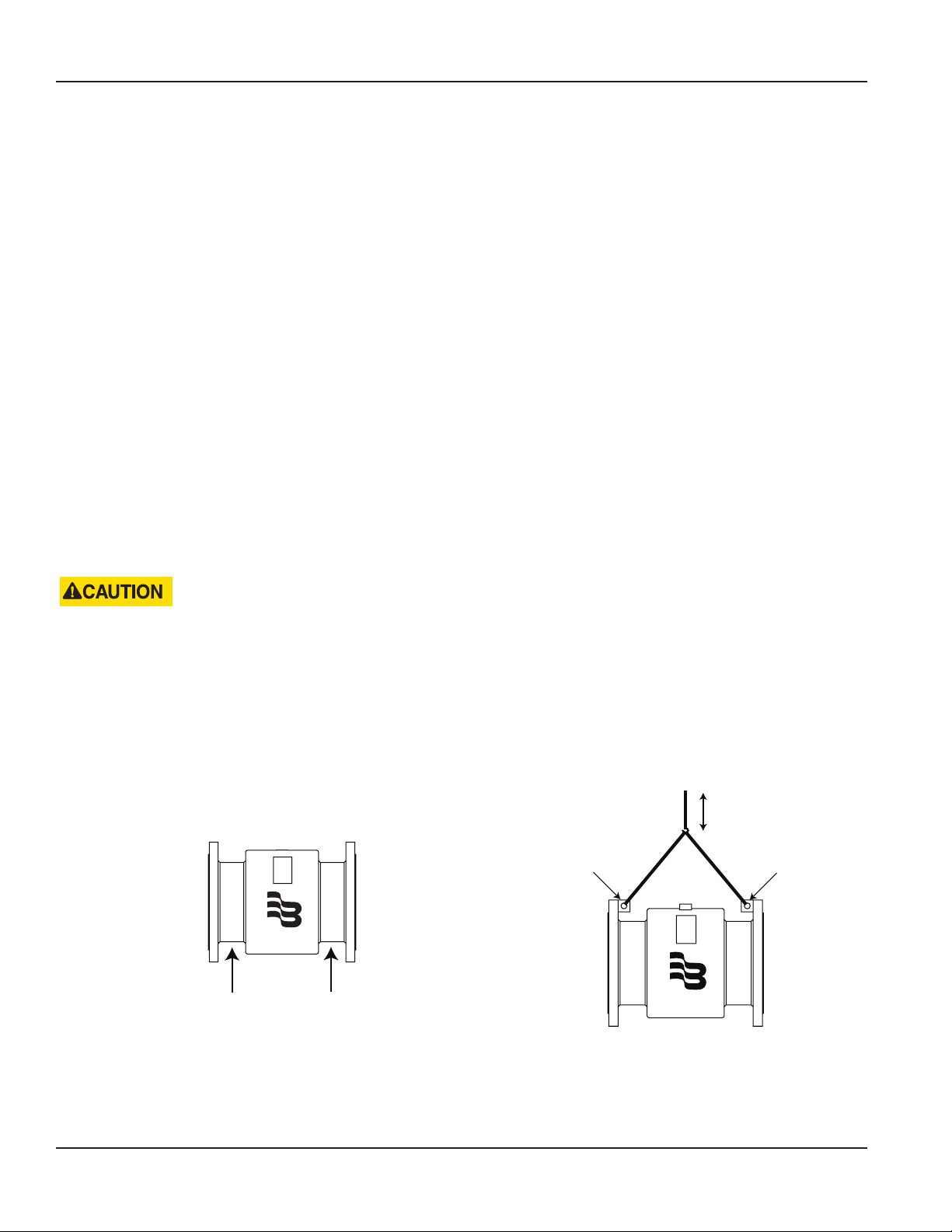
• Use the sling-rigged method to lift large detectors into a vertical position while they are still crated. Use this method
to position while they are still crated. Use this method to position large detectors vertically into pipelines.
Figure 3: Sling-Rigged Lifting Methods
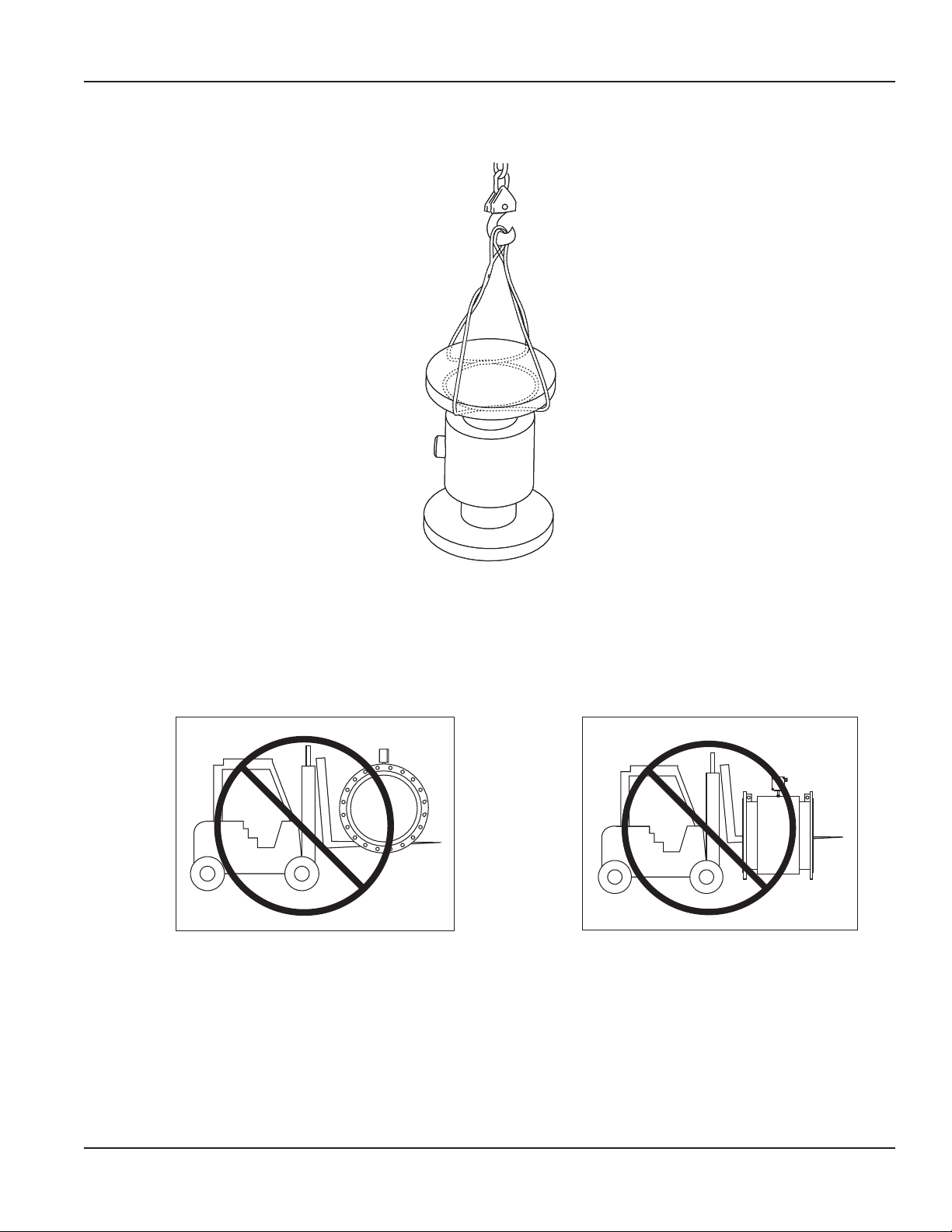
• Do not lift a detector with a forklift by positioning the detector body on the forks, with the flanges extending beyond
the lift. This could dent the housing or damage the internal coil assemblies.
• Never place forklift forks, rigging chains, straps, slings, hooks or other lifting devices inside or through the detector's
flow tube to hoist the unit. This could damage the isolating liner.
Do not lift detector with forklift. Do not lift or rig lifting devices through detector.
Figure 4: Lifting and Rigging Cautions
Page 7 August 2012
Page 8
M-Series® M2000 Electromagnetic Flow Meter
METER LOCATION, ORIENTATION AND APPLICATIONS
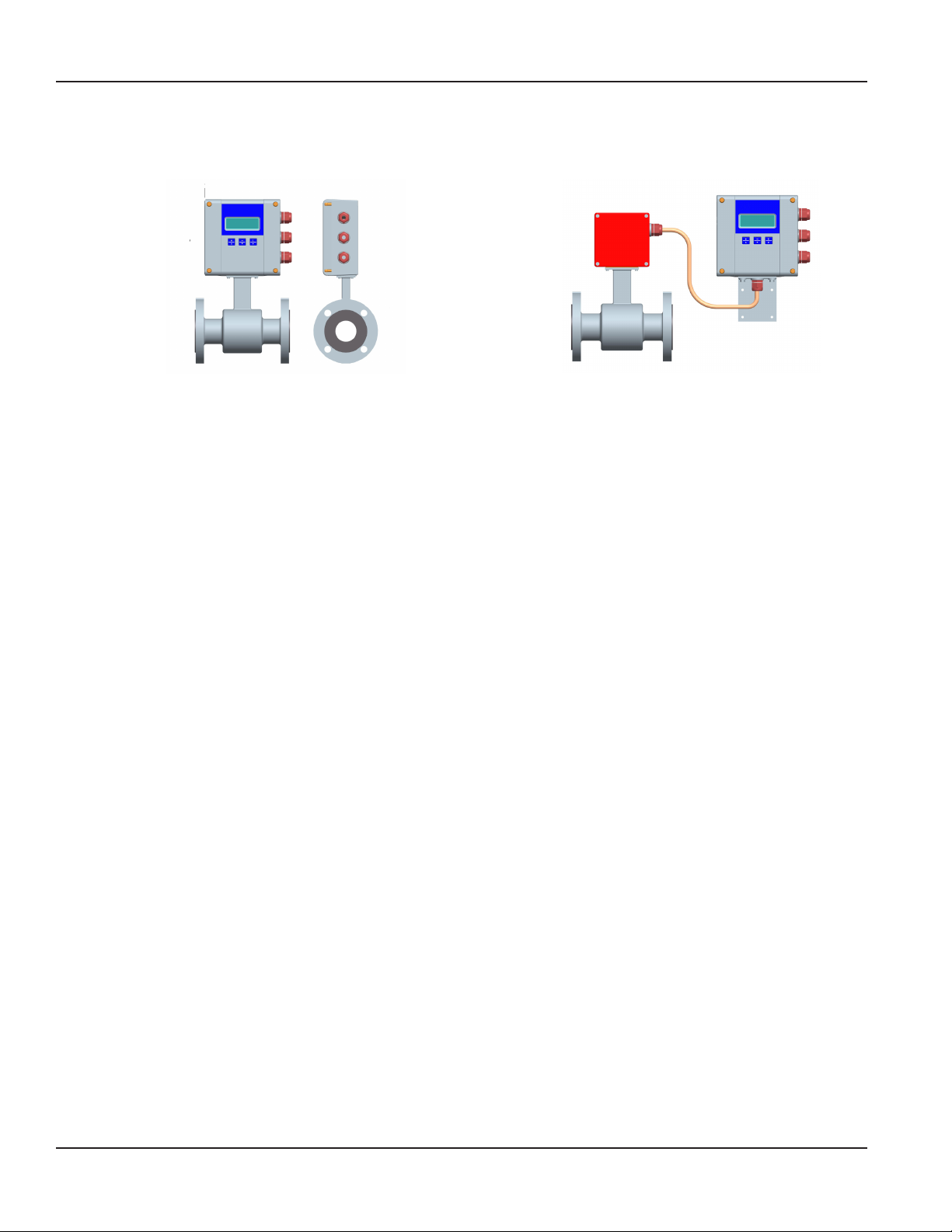
The M2000 provides two amplifier mounting options: an integral or meter mount option and a junction box/remote option.
Meter mount amplifier Junction box with remote amplifier
Figure 5: Amplifier Mounting Options
Remote Amplier Outdoor Location
The amplifier can be installed and operated outdoors. However, it must be protected from the elements, as follows:
• The ambient environment/temperature rating for the unit is –4…140° F (–20…60° C).
• If an indoor location is within 500 feet (152 meters) of the detector, consider increasing the cable length and
mounting the amplifier indoors.
• At minimum, fabricate a roof or shield over and/or around the amplifier to protect the LCD display screen from direct
sunlight.
Pipelines and Fluid Flow
Take the following precautions during installation:
• Do not install the meter on pipes with extreme pipe vibrations. If pipes are vibrating, secure the piping with
appropriate pipe supports in front of and behind the meter. If vibrations cannot be restrained, mount the amplifier in
a remote location.
• Do not install the detector close to pipeline valves, fittings or impediments that can cause flow disturbances.
• For detectors with PTFE liners, do not install the detector on suction sides of pumps.
• Do not install the detector on outlet sides of piston or diaphragm pumps. Pulsating flow can affect meter
performance.
• Avoid installing the detector near equipment that produces electrical interference such as electric motors, transformers,
variable frequency, and power cables.
• Verify that both ends of the signal cables are securely fastened.
• Place power cables and signal cables in separate conduits.
• Place the meter where there is enough access for installation and maintenance tasks.
Page 8 August 2012
Page 9
Installation & Operation Manual
Meter Orientation
Mag meters can operate accurately in any pipeline orientation and can measure volumetric flow in forward and reverse
directions.
OTE:N A "Forward Flow" direction arrow is printed on the detector label.
Vertical Placement
Mag meters perform best when placed vertically, with liquid flowing upward and meter electrodes in a closed, full pipe.
Figure 6: Vertical Placement
Vertical placement allows the pipe to remain completely full, even in low flow, low pressure applications, and it prevents
solids build-up, sediment deposit and accumulation on the liner and electrodes.
OTE:N Carefully observe the “Forward Flow” label on the meter body and install the meter accordingly. When
installed vertically, rotate amplifier so that cable glands are facing down.
Horizontal Placement
M2000 meters are equipped with an Empty Pipe Detection feature. If an electrode mounted in the pipe is not covered by fluid
for five seconds, the meter will display an Empty Pipe Detection condition. The meter will send out an error message and
stop measuring flow. When the electrode is again covered with fluid, the error message disappears and the meter will begin
measuring.
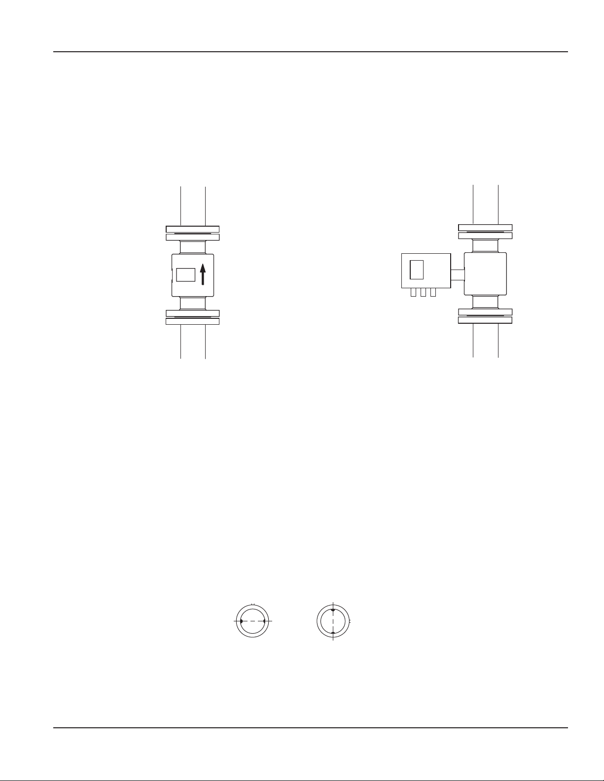
When installing the meter on a horizontal pipe, mount the detector to the pipe with the flow-measuring electrode axis in a
horizontal plane (three and nine o’clock). This placement helps prevent solids build-up, sediment deposit and accumulation
on the electrodes.
Electrode
Plane
Electrode
Plane
RIGHT
WRONG
Figure 7: Horizontal Placement
Page 9 August 2012
Page 10
M-Series® M2000 Electromagnetic Flow Meter
Straight Pipe Requirements
Sufficient straight-pipe runs are required at the detector inlet and outlet for optimum meter accuracy and performance. An
equivalent of three diameters of straight pipe is required on the inlet (upstream) side. Two diameters are required on the outlet
(downstream) side.
FLOWMETER
D (Pipe Size) D (Pipe Size)
FORWARD FLOW
ELBOW
CHECK VALVE
GLOBE VALVE
BUTTERFLY VALVE
PUMP
TEE
GATE VALVE
(FULLY OPEN)
MINIMUM STRAIGHT PIPE
MINIMUM STRAIGHT PIPE
7 x D
Figure 8: Straight Pipe Requirements
3 x D
STANDARD CONCENTRIC
REDUCERS
(NO DISTANCE REQUIRED)
MINIMUM PIPING REQUIREMENT
MINIMUM STRAIGHT PIPE
2 x D
ELBOW
TEE
ANY VALVE
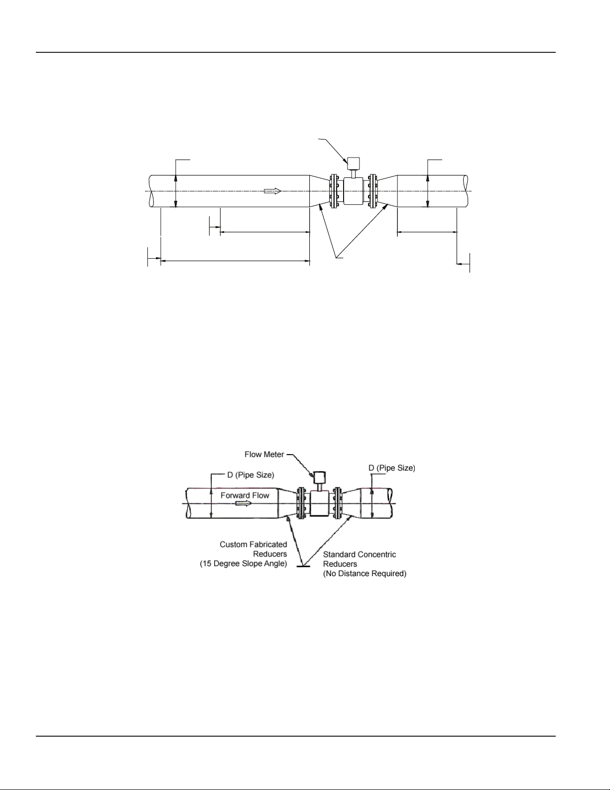
Pipe Reducer Requirements
With pipe reducers, a smaller meter can be mounted in larger pipelines. This arrangement may increase low-flow accuracy.
There are no special requirements for standard, concentric, pipe reducers.
Custom fabricated pipe reducers must have an approximate slope angle of 15 degrees to minimize flow disturbances and
excessive loss of head. If this is not possible, install the custom pipe reducers as if they were fittings and install the required
amount of straight pipe.
Figure 9: Pipe Reducer Requirements
Page 10 August 2012
Page 11
Installation & Operation Manual
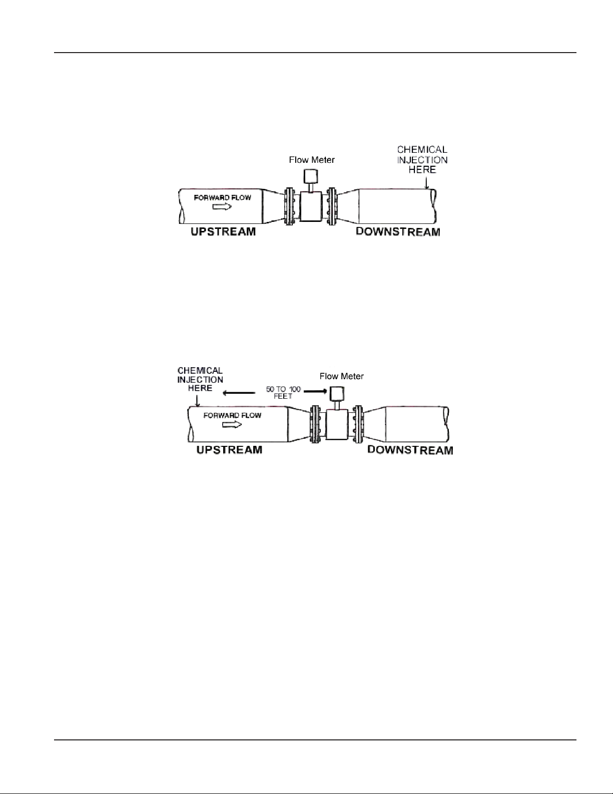
Chemical Injection Applications
For water line applications with a chemical injection point, install the meter upstream of the injection point. This eliminates
any meter performance issues.
Figure 10: Chemical Injection Point Upstream of Meter
If a meter must be installed downstream of a chemical injection connection, the distance between the meter and the
injection point should be between 50 and 100 feet (15 and 30 meters). The distance must be long enough to allow the water/
chemical solution to reach the meter in a complete, homogeneous mixture. If the injection point is too close, the meter senses
the two different conductivities for each liquid. This will likely result in inaccurate measurements. The injection method –
spaced bursts, continuous stream of drips or liquid or gas – can also affect downstream readings by the meter.
Figure 11: Chemical Injection Point Downstream of Meter
Sometimes, due to circumstances, it’s difficult to specify the exact downstream placement distances. Contact Badger Meter
Technical Support to review your application if necessary.
Page 11 August 2012
Page 12
WRONG
WRONG
RIGHT
FLOW
FLOW
FLOW
WRONG
FLOW
RIGHT
RIGHT
FLOW
FLOW
RIGHT
M-Series® M2000 Electromagnetic Flow Meter
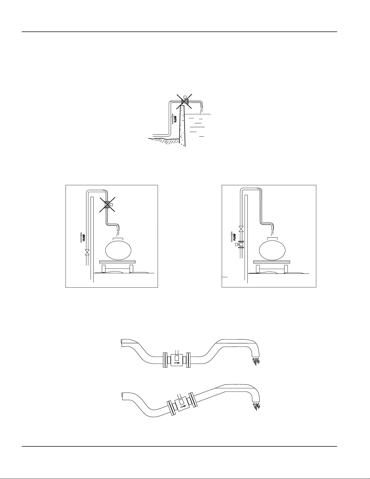
Partially-Filled Pipe Situations
In some locations, the process pipe may be momentarily only partially filled. Examples include: lack of back pressure,
insufficient line pressure and gravity flow applications.
To eliminate these situations, do not install the meter at the highest point of the pipeline.
FLOW
Figure 12: Incorrect Meter Placement
Do not install the meter in a vertical, downward flow section of pipe.
Always position the ON/OFF valves on the downstream side of the meter.
Do not install in a vertical, downward position. Position "On/Off" valves on downstream side.
Figure 13: Position Valves on Downstream Side
To minimize the possibility of partially-full pipe flows in horizontal, gravity or low pressure applications, create a pipe
arrangement that ensures the detector remains full of liquid at all times.
Page 12 August 2012
Figure 14: Pipe Positioned to Keep Water in Detector
Page 13
Installation & Operation Manual
METER GASKETS AND GROUNDING
Gasket and grounding requirements must be considered when determining the meter location, orientation and application.
Meter/Pipeline Connection Gaskets
You must install gaskets (not provided) between the detector's isolating liner and the pipeline flange to ensure a proper and
secure hydraulic seal. Use gaskets that are compatible with the fluid. Center each gasket on the flange to avoid flow
restrictions or turbulence in the line.
GASKETS RECOMMENDED
Figure 15: Meter/Pipeline Connection Gaskets
During installation, do not use graphite or any electrically conductive sealing compound to hold the gaskets. This could
compromise the accuracy of the measuring signal.
If you are using a grounding ring in the detector/pipeline connection, place the ring between two gaskets. (See
Non-Conductive Pipe Grounding section, page 14.)
Meter Grounding
Process pipeline material can be either electrically conductive (metal) or not electrically conductive (made of or lined with
PVC, fiberglass or concrete).
IMPORTANT
It is essential that the mag meter amplifier’s input ground (zero voltage reference)
be electrically connected to the liquid media and to a good, solid earth ground reference.
Conductive Pipe Grounding
To achieve an adequate ground, the meter body MUST be electrically connected to the liquid media. The mag meter flanges
are provided with grounding bolts for this purpose.
If the pipe material is electrically conductive, simply install grounding straps between these grounding bolts and the mating
flanges.
To ensure a good electrical connection at the mating flanges, we recommend that you drill and tap the flanges and install a
grounding screw (not provided).
These grounding straps must be copper wire, at least 12 AWG size. They must be connected on both sides (inlet and outlet) of
the detector and to a local, earth ground.
Page 13 August 2012
Page 14

GASKETS RECOMMENDED
GROUNDING RING
GROUNDING RING
M-Series® M2000 Electromagnetic Flow Meter
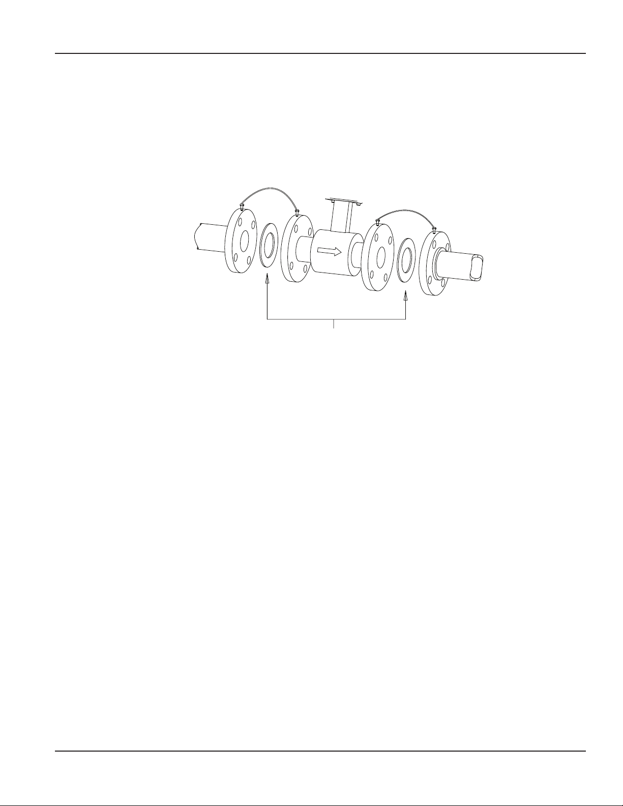
Non-Conductive Pipe Grounding
IMPORTANT
If the process pipe is not electrically conductive (PVC, fiberglass, cement-lined pipes or any other non-conductive material)
and the meter was not originally ordered with an optional grounding electrode, you must install a pair of grounding rings
between the mating flanges at both ends of the meter. See the following illustration.
Figure 16: Non-Conductive Pipe Grounding
In this case, the grounding straps should be connected to both of the grounding rings and to a good, solid earth ground.
Grounding rings are available in stainless steel. If your fluid is too aggressive for stainless steel, order a meter with the optional
grounding electrode in a material compatible with the fluid.
AMPLIFIER MOUNTING CONFIGURATION OPTIONS
There are two configuration options for mounting the amplifier. There are many options to accommodate a variety of
meter-placement and environmental conditions.
Meter Mount Conguration
The meter mount configuration has the amplifier mounted directly on the detector. This compact, self-contained
configuration minimizes installation wiring.
Remote Mount Conguration
The remote mount configuration places the amplifier at a location away from the fluid flow and detector. This is necessary in
situations where process fluid temperature or the environment exceeds amplifier ratings.
The detector and amplifier are connected by wires, run through conduit, between junction boxes on the detector and the
amplifier. The distance between the detector junction box and amplifier junction box can be up to 500 feet (152 meters). A
remote mounting bracket is supplied.
Submersible Option
If you are installing the meter in a vault, you should order the remote amplifier option. You must not install the amplifier inside
a vault. We also recommend ordering the remote meter package with the submersible option (NEMA 6P). This will eliminate
any potential problems resulting from humidity or temporary flooding in the vault.
OTE:N The National Electronics Manufacturer's Association (NEMA) 6P enclosures are constructed for indoor or outdoor use
to provide protection against access to hazardous parts; to provide a degree of protection against ingress of solid
foreign objects and water (hose directed water and the entry of water during prolonged submersion at a limited
depth); that provide an additional level of protection against corrosion and that will be undamaged by the external
formation of ice on the enclosure.
Page 14 August 2012
Page 15
WIRING
Wiring Safety
At installation, be sure to comply with the following requirements:
• Disconnect power to the unit before attempting any connection or service to the unit.
• Do not bundle or route signal lines with power lines.
• Keep all lines as short as possible.
• Use twisted pair shielded wire for all output wiring.
• Observe all applicable, local electrical codes.
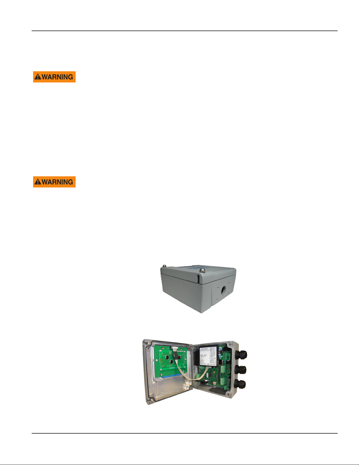
Opening the M2000 Cover
The M2000 amplifier's design lets you open the cover without completely removing it.
Cover is attached with display ribbon cable.
Installation & Operation Manual
To open the cover you will need a blade screwdriver.
Follow these steps:
1. Disconnect power to the unit.
2. Completely remove the two screws from either the left or the right side of
the amplier.
3. Loosen each of the remaining screws so that the round head of the screw clears the top edge of the cover.
4. Lift and pivot the cover into the open position.
Power Connections
Page 15 August 2012
Page 16
M-Series® M2000 Electromagnetic Flow Meter
External Disconnect
• Install an external disconnect switch or circuit breaker that meets local standards.
• Position the M2000 in an accessible location.
• Position and identify the disconnect device so as to provide safe and easy operation.
• Label the disconnect device as being for the mag meter.
AC Power Wiring
For the AC power connections, use three wire-sheathed cable with an overall cable diameter of 0.2…0.45 inch (5…12 mm).
For signal output, use 18…22 gauge (0.25…0.75 mm2) shielded wire. Overall cable diameter between 0.12…0.35 inch
(3…9 mm).
To prevent accidents, connect main power only after all other wiring has been completed.
The amplifier is a microprocessor device. It is important that the power supply be as “clean” as possible. Avoid using power
lines that feed heavy loads: pumps, motors, etc. If dedicated lines are not available, a filtering or isolation system may be
required.
Power wiring is the same for meter mount and remote mount amplifiers.
Remote Mount Installation
If you are installing the M2000 amplifier in a remote location, review the procedures in this section.
Mount Bracket to Amplifier
1. Align bracket-mounting holes with amplier mounting holes.
2. Attach bracket to amplier with supplied screws. Torque screws to 80 inch pounds.
Wiring Configuration
Wiring between the detector and the M2000 amplifier comes complete from the factory. If your installation requires the use
of conduit, we recommend that you follow these steps when wiring the detector to the amplifier.
1. Remove the junction box lid. Carefully remove the wires connected to the terminal blocks that run to the M2000
amplier. See the chart below for a reference of wire color to terminal connection.
2. Run cable through the conduit from the amplier location while retaining the wiring of the cable to the amplier, as
supplied.
3. Complete conduit assembly on both ends and rewire the cable into the junction box as it was previously wired.
Page 16 August 2012
Page 17
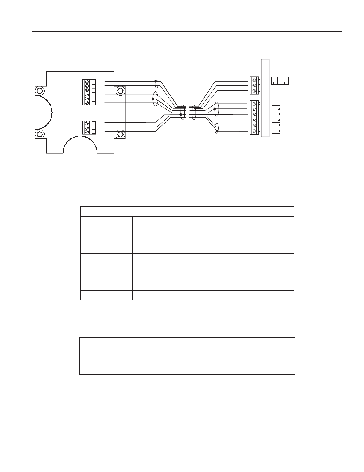
Wiring for Remote Configuration
Installation & Operation Manual
44
40
44
46
44
45
13
12
11
shield (black)
pink
brown
shield (black)
white
shield (black)
yellow
green
green
yellow
shield (black)
white
shield (black)
brown
pink
shield (black)
CS C2 C1
E1
ES
E2
RS
EP
ES
Figure 17: Wiring for Remote Configuration
Remote style M2000 amplifier models can be ordered with standard cables measuring 15, 30, 50 and 100 feet. In addition,
cables up to 500 feet are available.
Junction Box Amplifier
Connection No. Description Wire Color Connection
11 Coil Green C1
12 Coil Yellow C2
13 Main Shield Black (Red Ferrule) CS
45 Electrode White E1
44* Electrode Shield Black ES
46 Electrode Brown E2
40 Empty Pipe Pink EP
44* Empty Pipe Shield Black ES
*Connections with the No. 44 are lying on the same potential.
Empty Pipe Detection Considerations
Take into account the following cable length and conductivity requirements, if you will be using empty pipe detection.
Cable Length (Feet) Minimum Conductivity Required (µS/cm)
0* 5
100 20
500 100
* Meter Mount
Page 17 August 2012
Page 18
M-Series® M2000 Electromagnetic Flow Meter
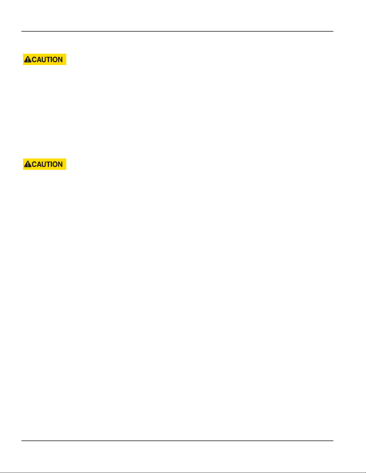
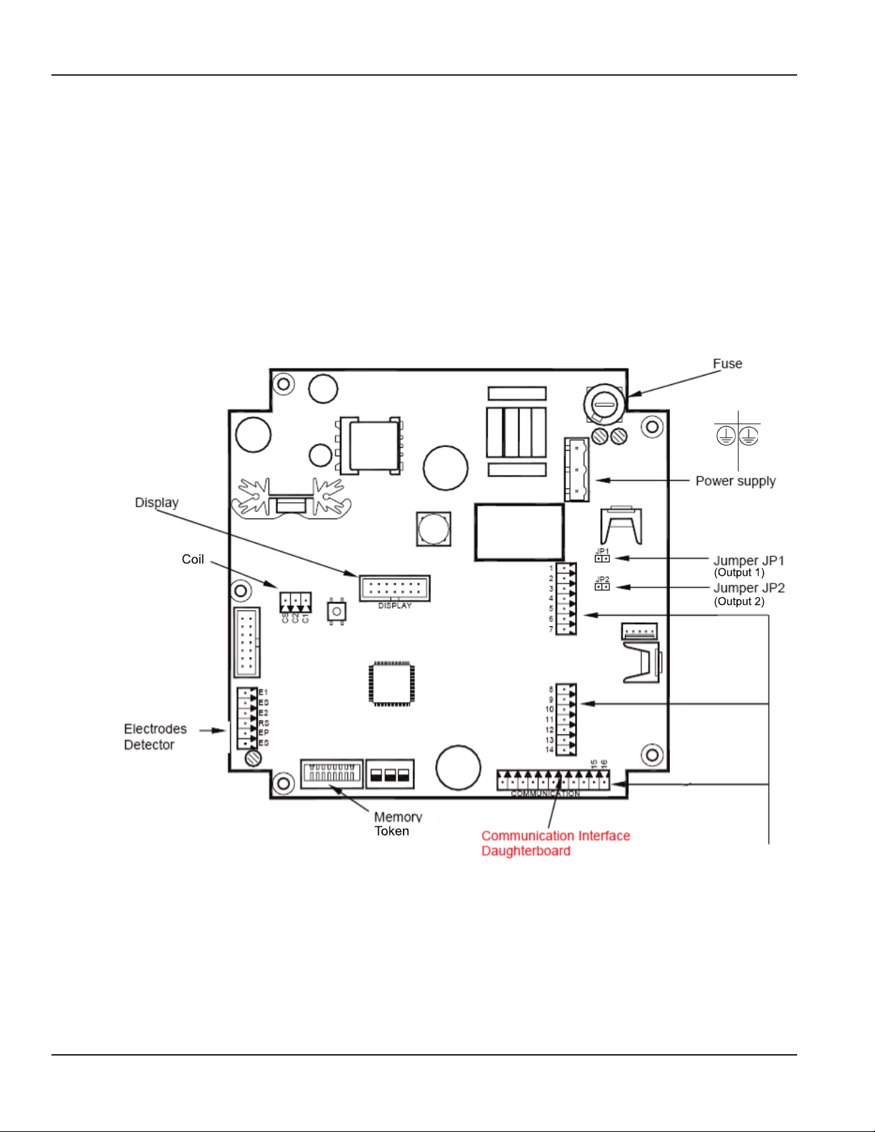
CONFIGURING INPUT/OUTPUT I/O
This section describes wiring the following M2000 inputs/outputs:
• Analog output
• Digital input
• Digital outputs
• Communication
Once the sensor and the amplifier have been wired, wire any inputs and outputs to the M2000 amplifier.
Do not connect the main power connection until you have made all other wiring connections. Follow all of the safety
precautions and local code to prevent electrical shock and damage to the electronic components.
AC DC
N
L
__
+
I/O
Connections
Supported protocols include:
RS485 MODBUS RTU
PROFIBUS DP
HART
Figure 18: Configuring Input/Output
Page 18 August 2012
Page 19

Installation & Operation Manual
Input/Output Description Terminal
Analog Output 0…20 mA Resistive Load < 800 ohms
4…20 mA Resistive Load < 800 ohms
16 (+)
15 (–)
0…10 mA Resistive Load < 800 ohms
2…20 mA Resistive Load < 800 ohms
Digital Output 1 Passive max. 30V DC, 100 mA
1 (+) and 2 (–)
Active 24V DC, 50 mA (set Jumper JP1)
Max. Frequency 10 kHz
Digital Output 2 Passive max. 30V DC, 100 mA
3 (+) and 4 (–)
Active 24V DC, 50 mA (set Jumper JP2)
Max. Frequency 10 kHz
Digital Output 3 Passive Max 30V DC, 100 mA, 10 kHz
Solid State Relay 48V AC, 500 mA, 1 kHz
10 (+) and 9 (–)
10 (+) and 11 (–)
* Software configurable
Digital Output 4 Passive Max 30V DC, 100 mA, 10 kHz
Solid State Relay 48V AC, 500 mA, 1 kHz
13 (+) and 12 (–)
13 (+) and 14 (–)
* Software configurable
Digital Input 5…30V DC 8 (+) and 9 (–)
Communications
(Port A)
RS232, configurable, MODBUS RTU, Remote Menu,
or Primo 3.1 Emulation.
7 GND
6 Rx
5 Tx
Analog Output Wiring Diagram
Figure 19: Analog Output Wiring Diagram
Page 19 August 2012
Page 20

M-Series® M2000 Electromagnetic Flow Meter
Digital Output Wiring Diagrams
Digital Input Wiring Diagram
Page 20 August 2012
Page 21

Installation & Operation Manual
PROGRAMMING THE M2000
The M2000 amplifier comes preprogrammed from the factory. Typically, you will not need to do any additional programming.
However, to take advantage of special features, you can program the meter for your specific needs. If you will be
programming the meter, familiarize yourself with the M2000 Function Buttons and follow the procedures outlined below.
Displays
There are two types of displays on the M2000:
• Menu Selection
• Numeric Entry
Menu Selection Display
Menu selection displays will appear in the following format:
DISPLAY TITLE
>Menu Selection 1
Menu Selection 2
DIRECTIONS LINE
Display format Example menu
The top line shows the title of the display screen. Below that are two visible menu selections. The bottom line provides
directions for user input.
Typically, a menu contains more options than will fit in the two menu selection lines. Press the [↑] and [↓] buttons to scroll the
display text up and down one line at a time. When the arrow is pointed to your desired menu option, press [E] to select the
item and open its display.
Numeric Entry Display
Numeric entry displays will appear in the following format:
DISPLAY TITLE
Description Line
Numeric Value
DIRECTIONS LINE
Display format Example numeric entry display
The top line shows the title of the display screen. The second line is a description of the value. The third line shows the
current value. The bottom line provides directions for user input.
START MENU
>Exit this Menu
Main Menu
ENTER:>
MORE:
↑,↓
LOW FLOW CUTOFF
% of 300.000 GPM
2.00%
CHG: +,- NEXT:E
Page 21 August 2012
Page 22

M-Series® M2000 Electromagnetic Flow Meter
OTE:N The bottom line of a numeric-value display provides prompts regarding the function of each button. The [+] or [–]
button will change the value of the numeral. The [E] button will move the cursor one digit to the right. When the
cursor is at the final, right-most digit, pressing [E] will reposition the cursor at the left-most digit. The bottom line
display will change to reflect the new function of the [E] button. Press [E] to save the current entry. Press [+] to edit
the current entry.
LOW FLOW CUTOFF
% of 300.000 GPM
3.00%
EDIT:+ SAVE:E
Details on how to change and set numeric values are described in the following section.
Function Buttons
All M2000 programming is accomplished using the three function buttons located on the front of the amplifier:
OTE:N Throughout this manual, the buttons will be referred to as: [↑] or [+] and [↓] or [–], depending on the context. The
"Enter" button will be referred to as [E].
Consider the [+ | ↑] button as the "next step" or "scroll text up" button. During programming, pressing this button will
go to the next menu selection, or increment a numeral.
Example 1: The illustration below shows the M2000 Main Menu. The selection arrow is pointing to the Exit this Menu
selection.
To scroll up to the menu's next selection, press [↑] once. The menu text scrolls up to the next menu selection, Main Menu.
START MENU
>Exit this Menu
Main Menu
MORE:
Example 2: Some procedures require you to enter a numeric value. The [+] button is used to increment the selected numeral.
The illustration below shows the Low Flow Cutoff parameter display. Notice the cursor under the 2 in the ones' place. In this
case, press [+] once to increment the numeral to the value of 3.00%.
↑,↓ ENTER:>
LOW FLOW CUTOFF
% of 300.000 GPM
2.00%
CHG: +,- NEXT:E
Press [↑]
Press [+]
START MENU
> Main Menu
Quick Setup
MORE:
↑,↓ ENTER:>
LOW FLOW CUTOFF
% of 300.000 GPM
3.00%
CHG: +,- NEXT:E
Page 22 August 2012
Page 23

Installation & Operation Manual
Consider the Down Arrow [ – | ↓ ] button as the "previous step" button. During a procedure, pressing this button will go
to the menu's previous selection or decrement a numeral.
Example 1: The illustration below shows the M2000 Main Menu. The selection arrow is pointing to the Meter Setup selection.
To scroll the text down to the menu's previous selection, Exit this Menu (which is not visible on the display), press [↓] once.
MAIN MENU
>Meter Setup
Press [↓]
Measurements
MORE:
Example 2: For procedures that require you to enter a numeric value, the [-] button is used to decrement the selected
numeral. The illustration below shows the Low Flow Cutoff parameter display. Notice the cursor under the 3 in the ones' place.
In this case, press the [-] once to decrement the numeral to the value of 2.00 %.
↑,↓ ENTER:>
LOW FLOW CUTOFF
% of 300.000 GPM
Press [–]
3.00%
CHG: +,- NEXT:E
The [E] button functions as an "Enter" button, or "cursor right" button.
Example 1: The illustration below shows the M2000 Main Menu. The selection arrow is pointing to the Meter Setup selection.
Press [E] to select Meter Setup, and open the Meter Setup display.
MAIN MENU
>Meter Setup
Press [E]
Measurements
MORE:
↑,↓ ENTER:>
MAIN MENU
>Exit this Menu
Meter Setup
MORE:
↑,↓ ENTER:>
LOW FLOW CUTOFF
% of 300.000 GPM
2.00%
CHG: +,- NEXT:E
METER SETUP
>Exit this Menu
Scale Factor
MORE:
↑,↓ ENTER:>
In cases where you are entering a numeric value, the [E] button does not function as the "Enter" button, but rather, will move
the cursor to the right. When the cursor is at the right-most position, the [E] will now serve as the Enter key.
Example 2: The illustration below shows the Low Flow Cutoff display. The cursor is under the 3 in the ones' place. In this case,
press [E] to move the cursor to the right one digit.
LOW FLOW CUTOFF
% of 300.000 GPM
3.00%
CHG: +,- NEXT:E
Press [E]
LOW FLOW CUTOFF
% of 300.000 GPM
3.00%
CHG: +,- NEXT:E
Page 23 August 2012
Page 24

M-Series® M2000 Electromagnetic Flow Meter
SECURITY
The M2000 security feature gives you the option to restrict access to the meter by way of a five-digit Personal Identification
Number (PIN). The system administrator can set up a single PIN for each of the three different levels of access:
• Administration – allows access to all M2000 menu configuration screens.
• Service – allows access to service-level and user-level menu configuration screens.
• User – allows access only to user-level menu configuration screens.
Not all levels of access need to be set. If no PINs are set up, any M2000 user will have access to all functions.
OTE:N The security settings will also apply to remote access. All remote writes to the meter will be blocked unless the user is
remotely logged in.
Setting the Administration PIN
Users logged in with the Administration PIN have access to all M2000 menu configuration screens.
To set the administrator's PIN, follow these steps from the Advanced menu:
1. Select Security to view the Security menu.
2. Select Set Admin PIN to view the Admin PIN display.
3. Set the ve-digit PIN number to the desired value.
4. Press [E] to save the PIN and to return to the Security menu.
Setting the Service PIN
Users logged in with the Service PIN have access to service level menu configuration screens. Service users will not have
access to administrative screens.
OTE:N In order to set a service-level PIN, you must first set up an administration PIN.
To set the service PIN, follow these steps from the Advanced menu:
1. Select Security to view the Security menu.
2. Select Set Service PIN to view the Service PIN display.
3. Set the ve-digit PIN number to the desired value.
4. Press [E] to save the PIN and to return to the Security menu.
Setting the User PIN
Users logged in with this User PIN have access to user-level procedures. Users will not have access to administrative or service
screens.
OTE:N In order to set a user-level PIN, you must first set up an administration PIN and a service PIN.
To set the user's PIN, follow these steps from the Advanced menu:
1. Select Security to view the Security menu.
2. Select Set User PIN to view the User PIN display.
3. Set the ve-digit PIN number to the desired value.
4. Press [E] to save the PIN and to return to the Security menu.
Page 24 August 2012
Page 25

Installation & Operation Manual
Entering Your Personal Identication Number (PIN)
If your system has been set up with PIN security, you will need to enter a PIN to access programming functions. There are
three possible access levels, each with its own unique PIN: User, Service and Administration. Your system administrator will
provide you with the appropriate PIN.
OTE:N All PINs are factory set to 00000. At this setting, you will not be required to enter a PIN. If the system administrator has
not set the PIN, pressing [E] from the Start Screen opens the Main Menu.
If you forget or misplace your PIN, call Badger Meter Customer Service to get a master password. When you call, have
the security code that appears in the upper right corner of the PIN Request display.
Follow these steps to enter your PIN in the M2000:
1. At the Main Menu, press [E]. The PIN Request display opens.
PIN REQUEST 12345
Security Code
Please enter
pin #: 00000
CHG:+,- NEXT:E
2. Press [+] to increment the numeral.
3. Press [E] to move the cursor to the next digit.
4. Repeat the steps to set each of the ve digits to match your PIN.
5. Press [E]. If you entered a valid PIN, the Main Menu opens indicating your level of access.
If you entered the wrong PIN, you will see the following display:
MENU ACCESS
DENIED
• Press [E] to return to the PIN Request display.
• Repeat Steps 1 through 5.
OTE:N Be sure to log off when you have completed work with the M2000. Otherwise, there will be a five-minute delay
between your last activity and the time when the M2000 will automatically log you off.
Page 25 August 2012
Page 26

M-Series® M2000 Electromagnetic Flow Meter
SETTING UP THE M2000 WITH QUICK SETUP
The M2000 provides you with a Quick Setup utility that allows you to set or change your Flow Units, Totalizer Units, Full Scale
Flow and Low Flow Cutoff settings. To open the Quick Setup, select Quick Setup from the Start Menu.
Quick Setup
Flow Unit
[GPM]
Totalizer Unit
[USG]
Flow Unit lets you set the unit of measure for the flow rate and full scale flow.
To change the Flow Unit value, follow these steps from the Quick Setup menu.
1. Select Flow Unit to view the Flow Unit display.
2. Press [↑] or [↓] to position the arrow next to one of the following Flow Units:
Code Flow Unit Code Flow Unit
LPS Liter/Second GPM Gallons/Min
LPM Liter/Minute GPH Gallons/Hour
LPH Liter/Hour MGD MegaGallon/Day
M3S Cubic Meter/Sec IGS UKG/Sec
M3M Cubic Meter/Min IGM UKG/Min
M3H Cubic Meter/Hour IGH UKG/Hour
F3S Cubic Feet/Sec LbM Pound/Min
F3M Cubic Feet/Min OPM Ounce/Min
F3H Cubic Feet/Hour BPM Barrel/Min
GPS Gallons/Sec — —
3. Press [E] to save the Flow Units setting.
Totalizer Unit establishes the units of measure for the totalizers.
To change the Totalizer Unit value, follow these steps from the Totalizer Unit display.
1. Press [↑] or [↓] to position the arrow next to one of the following Totalizer Units:
Code Totalizer Unit Code Totalizer Unit
L Liters UKG Imperial Gallons
HL HectoLiters Lb Pounds
3
M
Cubic Meters Oz Fluid Ounces
CFt Cubic Feet Aft Acre Feet
USG U.S. Gallons BBL Barrel
MG MegaGallons — —
2. Press [E] to save the Totalizer Units setting.
Page 26 August 2012
Page 27

Installation & Operation Manual
Quick Setup
Full Scale Flow Full Scale Flow sets the maximum flow the system is expected to measure. This parameter has
influence on other system parameters. These parameters include:
• Frequency Output – Full scale frequency is observed at full scale flow
• Low Flow Cutoff – Changes to full scale flow affect the measuring cut-off threshold of the meter
• Alarm Outputs – Changes to full scale flow adjusts the thresholds for generating set point alarms
• Pulse Outputs – Changes to full scale flow adjusts the pulse frequency and duty cycle
• Analog Outputs – Changes to full scale flow adjusts the interpretation of the analog output signal
Change the full scale flow based on the meter size and the application’s requirements. Verify that the
full scale flow falls within the meter’s suggested flow range limits. In terms of flow velocity, the meter's
limits are from 0.1 to 39.4 feet/second.
The full scale flow is valid for both flow directions.
OTE:N If the flow rate exceeds the full scale setting, an error message indicates that the configured
full scale range has been exceeded. However, the meter will continue to measure. This will
affect the latency of the pulse outputs and possibly cause overflow. Furthermore, the analog
output may also be placed in alarm mode.
To set or change the Full Scale Flow, follow these steps from the Quick Setup menu:
1. Select Full Scale Flow to view the Full Scale Flow display.
2. Set the full scale flow value to the desired setting.
3. Press [E] to save the full scale flow value and return to the Measurements menu.
Low Flow Cutoff Low Flow Cutoff defines the threshold at which flow measurement will be forced to zero. The cutoff
value can be set from 0% to 10% of the full scale flow. Increasing this threshold will help prevent false
readings during “no flow” conditions possibly caused by pipe vibration or inherent system noise.
To change Low Flow Cutoff, follow these steps from the Low Flow Cutoff display.
1. Set the Low Flow Cutoff value to the desired setting, between 0% and 10%.
2. Press [E] to save the value.
Page 27 August 2012
Page 28

M-Series® M2000 Electromagnetic Flow Meter
QUICK REFERENCE
Main Menu
Meter Setup Scale Factor
Empty Pipe Detect
Power Line Freq
Excitation Freq
Pipe Diameter
Detector Factor
Detector Offset
Measurements Flow Unit
Totalizer Unit
Full Scale Flow
Low Flow Cutoff
Flow Direction
Damping Factor
Inputs/Outputs Analog Output
Digital Input 1
Digital Output 1
Digital Output 2
Digital Output 3
Digital Output 4
Flow Simulation
Clear Totals T1
T2
PS
Tpwroff
Communications Port A Settings
Port B Settings
Diagnostics
Advanced Data Logger
Token Copy
ADE
Unit Multiplier
Backlight Control
Analog Calibrate
Software Filter
Empty Pipe Cal.
Security
Info/Help Error Counts
Rollover Counts
Power Up Counter
Power Off Totalizer
Version Info
Serial Number
Meter Tag Name
Daughterboard Info
Polarization Volt
Restore Defaults
Language Select English
Espanol
Page 28 August 2012
Page 29

Installation & Operation Manual
USING THE M2000 MAIN MENU PROGRAMMING OPTIONS
The following M2000 programming options are available from the Main Menu:
• Meter Setup
• Measurements
• Inputs/Outputs
• Clear Totals
• Communications
• Advanced
• Info/Help
• Language Select
In the section that follows, the applicable security level for each menu option is indicated as follows:
A
Administrative Service User
Options that can be set at Quick Setup are indicated with:
The factory default values are shown, enclosed in brackets.
OTE:N Options that are listed [Factory Set] should not be changed without specific directions from authorized Badger Meter
personnel.
Meter Setup
Scale Factor
[0.0%]
S
Empty Pipe Detect
[Off ]
S
Changing the scale factor lets you adjust the meter's accuracy without disturbing factory-set
parameters. You can tune the meter to meet changing application requirements. For example, if the
meter is under registering by 0.5 percent then set the scale factor to +0.5%. If the meter is over
registering by 0.5 percent then set the scale factor to –0.5%.
To set the Scale Factor, follow these steps from the Meter Setup menu:
1. Select Scale Factor, to open the Detector Factor display.
2. Set the Detector Factor value to the desired setting.
3. Press [E], to save the new value and return to the Meter Setup menu.
When set to On, Empty Pipe Detect indicates to the outputs and the display that the meter is not
completely filled. When set to Off, empty pipe detect is disabled.
Enabling empty pipe detect requires a one-time calibration. Calibration is described in the Advanced
menu section under Empty Pipe Cal.
To set Empty Pipe Detect, follow these steps from the Meter Setup menu:
1. Select Empty Pipe Detect to view the Empty Pipe Detect display.
2. Position the arrow next to On or Off.
3. Press [E] to save the Empty Pipe Detect On or Off and return to the Meter Setup menu.
S
U
Page 29 August 2012
Page 30
M-Series® M2000 Electromagnetic Flow Meter
Meter Setup
Power Line Freq
[60 Hz]
S
Excitation Freq
[Factory Set]
A
Pipe Diameter
[Factory Set]
A
Power Line Freq provides measuring immunity to industrial noise from a power supply feed.
To set Power Line Frequency, follow these steps from the Meter Setup menu:
1. Select Power Line Freq to view the Power Line Frequency display.
2. Position the arrow next to 50 Hz or 60 Hz.
3. Press [E] to save the power line frequency and return to the Meter Setup menu.
The Excitation Freq parameter is set at the factory. You can change Excitation Freq to configure the DC
excitation of the coils. Supported frequencies are dependent on the configured power line frequency:
50 Hz 60 Hz
1 Hz 1 Hz
3.125 Hz 3.75 Hz
6.25 Hz 7.5 Hz
12.5 Hz 15 Hz
To change Excitation Frequency, follow these steps from the Meter Setup menu:
1. Select Excitation Freq to view the Excitation Frequency display.
2. Position the arrow next the desired frequency.
3. Press [E] to save the excitation frequency and return to the Meter Setup menu.
The Pipe Diameter parameter is set at the factory. In the event the amplifier is replaced, verify that the
pipe diameter matches the installed pipe size.
To change Pipe Diameter, follow these steps from the Meter Setup menu:
1. Select Pipe Diameter to open the Pipe Diameter display.
2. Position the arrow next to one of the following pipe diameters.
6 mm [1/4"] 65 mm [2-1/2"] 400 mm [16"] 1000 mm [40"]
8 mm [1/4"] 80 mm [3"] 450 mm [18"] 1050 mm [42"]
10 mm [1/4"] 100 mm [4"] 500 mm [20"] 1200 mm [48"]
15 mm [1/4"] 125 mm [5"] 550 mm [22"] 1400 mm [54"]
20 mm [1/4"] 150 mm [6"] 600 mm [24"] 1600 mm [64"]
25 mm [1"] 200 mm [8"] 700 mm [28"] 1800 mm [72"]
32 mm [1-1/4"] 250 mm [10"] 750 mm [30"] 2000 mm [80"]
40 mm [1-1/2"] 300 mm [14"] 800 mm [32"] Other
50 mm [2"] 350 mm [14"] 900 mm [36"] —
3. Press [E] to save the pipe diameter and return to the Meter Setup menu.
Page 30 August 2012
Page 31

Meter Setup
Installation & Operation Manual
Detector Factor
[Factory Set]
A
Detector Offset
[Factory Set]
A
Flow Units
[GPM]
U
The Detector Factor parameter is set at the factory. This factor compensates for accuracy error as a result
of the installed detector. If accuracy adjustment of the meter is required, please refer to the scale factor.
In the event the amplifier is replaced, this parameter must be reprogrammed with the original detector
factor.
The Detector Offset parameter is set at the factory. This parameter compensates for accuracy error as a
result of the installed detector. If accuracy adjustment of the meter is required, please refer to the scale
factor.
Measurements
Flow Units lets you set the unit of measure for the flow rate and full scale flow. Changing the flow units
parameter readjusts the full scale flow parameter. For example, changing from gpm to gps would
change the full scale flow from 60 gpm to 1 gps.
To change the Flow Unit, follow these steps from the Measurements menu:
1. Select Flow Units to view the Flow Units display.
2. Position the arrow next to one of the following flow unit options:
Code Flow Unit Code Flow Unit
LPS Liter/Second GPM Gallons/Min
LPM Liter/Minute GPH Gallons/Hour
LPH Liter/Hour MGD MegaGallon/Day
M3S Cubic Meter/Sec. IGS UKG/Sec.
M3M Cubic Meter/Min IGM UKG/Min
M3H Cubic Meter/Hour IGH UKG/Hour
F3S Cubic Feet/Sec. LbM Pound/Min
F3M Cubic Feet/Min OPM Ounce/Min
F3H Cubic Feet/Hour BPM Barrel/Min
GPS Gallons/Sec.
3. Press [E] to save the flow units and return to the Measurements menu.
Page 31 August 2012
Page 32

M-Series® M2000 Electromagnetic Flow Meter
Measurements
Totalizer Unit
[USG]
U
Full Scale Flow
[Factory Set]
U
The Totalizer Unit parameter establishes the units of measure for the totalizers.
To change the Totalizer Unit value, follow these steps from the Measurements menu:
1. Select Totalizer Unit to view the Totalizer Unit display.
2. Position the arrow next to one of the following totalizer units:
Code Totalizer Unit Code Totalizer Unit
L Liters UKG Imperial Gallons
HL HectoLiters Lb Pounds
3
M
CFt Cubic Feet Aft Acre Feet
USG U.S. Gallons BBL Barrel
MG MegaGallons — —
3. Press [E] to save the totalizer unit and return to the Measurements menu.
The Full Scale Flow parameter sets the maximum flow the system is expected to measure. This
parameter has influence on other system parameters. These parameters include:
• Frequency Output – Full scale frequency is observed at full scale flow
• Low Flow Cutoff – Changes to full scale flow affect the measuring cut-off threshold of the meter
• Alarm Outputs – Changes to full scale flow adjusts the thresholds for generating set point alarms
Cubic Meters Oz Fluid Ounces
• Pulse Outputs – Changes to full scale flow adjusts the pulse frequency and duty cycle
• Analog Outputs – Changes to full scale flow adjusts the interpretation of the analog output signal
Change the full scale flow based on the meter size and the application’s requirements. Verify that the
full scale flow falls within the meter’s suggested flow range limits. In terms of flow velocity, the meter's
limits are from 0.1 to 39.4 feet/second.
The full scale flow is valid for both flow directions.
OTE:N If the flow rate exceeds the full scale setting, an error message indicates that the configured full
scale range has been exceeded. However, the meter will continue to measure. This will affect
the latency of the pulse outputs and possibly cause overflow. Furthermore, the analog output
may also be placed in alarm mode.
To change the Full Scale Flow, follow these steps from the Measurements menu:
1. Select Full Scale Flow to view the Full Scale Flow display.
2. Set the full scale flow value to the desired setting.
3. Press [E] to save the full scale flow value and return to the Measurements menu.
Page 32 August 2012
Page 33

Measurements
Installation & Operation Manual
Low Flow Cutoff
[0.2%]
U
Flow Direction
[Bi-Directional]
U
Low flow cutoff defines the threshold at which flow measurement will be forced to zero. The cutoff
value can be set from 0% to 10% of the full scale flow. Increasing this threshold will help prevent false
readings during “no flow” conditions possibly caused by pipe vibration or inherent system noise.
To change the Low Flow Cutoff value, follow these steps from the Measurements menu:
1. Select Low Flow Cutoff to view the Low Flow Cutoff display.
2. Set the low flow cutoff value to the desired setting.
3. Press [E] to save the new low flow cutoff value.
Flow Direction lets you set the meter to measure forward flow only (uni-directional) or both forward and
reverse flow (bi-directional).
Uni-Directional
Flow is totalized in only one direction. The flow direction is indicated by the arrow printed on the
detector label. Uni-directional measurements on the main display screen include:
• T1: Registers forward flow, resettable by menu or MODBUS RTU
• T2: Registers forward flow, resettable by menu, MODBUS RTU, or digital input configured for
Remote Reset
Bi-Directional
Flow is totalized in both directions. Bi-directional measurements on the main display screen include:
• T+: Registers forward flow, resettable by menu or MODBUS RTU
• T–: Registers reverse flow, resettable by menu or MODBUS RTU
• TN: Registers total flow, T+ – T–, resettable by menu or MODBUS RTU
Damping Factor
[No Damping]
U
To change the flow direction follow these steps from the Measurements menu.
1. Select Flow Direction to view the Flow Direction display.
2. Select Uni-Directional or Bi-Directional.
3. Press [E] to save the flow direction and return to the Measurements menu.
The damping factor establishes the stability of the measured flow rate. If back and forth oscillations of
the flow rate are observed during normal flow conditions, increase this value incrementally until the
flow rate stabilizes. This parameter has no affect on the totalizers.
To change the Damping Factor value, follow these steps from the Measurements menu.
1. Select Damping Factor to view the Damping Factor display.
2. Select one of the following damping factors:
1 Second 10 Seconds
2 Seconds 20 Seconds
3 Seconds 30 Seconds
4 Seconds No Dampening
5 Seconds
3. Press [E] to save the damping factor and return to the Measurements menu.
Page 33 August 2012
Page 34

M-Series® M2000 Electromagnetic Flow Meter
Analog Output Range
[4 to 20 mA]
S
The Analog Output parameter establishes the range of the analog output signal. To
change Analog Output range, follow these steps from the Inputs/Outputs menu:
1. Select Analog Output to view the Analog Output display.
2. Select one of the following options:
• 4 to 20 mA
• 0 to 20 mA
• 2 to 10 mA
• 0 to 10 mA
3. Press [E] to save the analog output and return to the Inputs/Outputs menu:
Inputs/Outputs
Alarm Mode
[OFF]
S
Digital Input Digital Input lets you configure the functional operation of the digital input. The following functions are
supported:
• Remote Reset – Clears totalizer T2 (uni-directional)
This parameter configures the behavior of the analog output during alarm conditions.
Three options exist for this parameter: OFF, LOW, and HIGH.
OFF: Analog signal is based on flow rate and always within the configured range
LOW: During alarm conditions, the analog signal will be 2 mA less than the
configured lower range
HIGH: During alarm conditions, the analog signal will be 2 mA more than the
configured upper range
For example, if the analog range is 4 to 20 mA and the alarm mode is set to HIGH, then
during a full scale flow alarm condition, the analog output current will be 22 mA.
To change the analog output alarm mode, follow these steps from the Inputs/Outputs
menu:
1. Select Alarm Mode to view the Alarm Mode display.
2. Select one of the following options:
• OFF
• LOW
• HIGH
3. Press [E] to save the alarm mode and return to the Inputs/Outputs menu.
• Batch Reset – Resets batch totalizer PS to preset amount and clears T2 (uni-directional)
• Pos Zero Return – Forces flow rate to zero (does not totalize)
• ADE – Input configured for ADE operation. See "ADE Interface" on page 52.
To change Digital Input, follow these steps from the Inputs/Outputs menu:
1. Select Digital Input to view the Digital Input display.
2. Select the desired function.
3. Press [E] to save the digital input and return to the Inputs/Outputs menu.
Page 34 August 2012
Page 35

Digital Output Pulses/Unit
[1]
Installation & Operation Manual
Inputs/Outputs
The Pulses/Unit parameter lets you set how many pulses per unit of measure will be
transmitted to remote applications. For example, assuming the unit of measure is
gallons:
S
Pulse Width
[0 ms]
S
• Setting the Pulses/Unit to 1 will transmit 1 pulse every gallon
• Setting the Pulses/Unit to 0.01 will transmit 1 pulse every 100 gallons
You must configure pulses/unit if the function of the selected output is to be
forward, reverse or AMR pulse.
This parameter must be considered with the Pulse Width and Full Scale Flow
parameters. The maximum pulse frequency is 10 kHz. The frequency is correlated
with the flow rate. Violation of output frequency limits will generate a configuration
error.
To change the pulses/unit, follow these steps from the Inputs/Outputs menu:
1. Select Digital Output 1 or 2 and press [E] to open the Digital Output menu.
2. From the Digital Output menu select Pulses/Unit, and press [E] to open the
Pulses/Unit display.
3. Enter the pulses/unit value. Press [E] to save the new parameter and return to
the Digital Output menu.
The Pulse Width parameter establishes the On duration of the transmitted pulse. The
configurable range is from 0 to 1000 ms.
• Non-zero pulse width configuration – the Off duration of the transmitted pulse
is dependent on flow rate. The Off duration is to be at least the configured On
duration. At full scale flow, the On duration equals the Off duration. The
maximum configurable output frequency is limited to 500 Hz.
• 0 ms pulse width configuration – the duty cycle of the transmitted pulse is at 50
percent allowing for a maximum configurable output frequency of 10 kHz.
This parameter must be considered with the Pulses/Unit and Full Scale Flow
parameters. The maximum pulse frequency is 10 kHz. The frequency is correlated
with the flow rate. Violation of output frequency limits will generate a configuration
error.
To change the pulse width, follow these steps from the Inputs/Outputs menu:
1. Select Digital Output 1 or 2 and press [E] to open the Digital Output menu.
2. From the Digital Output menu select Pulse Width, and press [E] to open the
Pulse Width display.
3. Enter the pulse width value. Press [E] to save the new parameter and return to
the Digital Output menu.
Page 35 August 2012
Page 36

M-Series® M2000 Electromagnetic Flow Meter
Digital Output Preset Amount
[0.0]
Preset amount lets you set the reset value for the associated PS totalizer when the
digital input is set to Batch Reset.
To change the preset amount, follow these steps from the Inputs/Outputs menu:
Inputs/Outputs
S
Set Point Min.
[0%]
S
Set Point Max.
[100%]
1. Select Digital Output 1, 2, 3 or 4 and press [E] to open the Digital Output
menu.
2. From the Digital Output menu select Preset Amount, and press [E] to open the
Preset Amount display.
3. Enter the preset amount value. Press [E] to save the new parameter and return
to the Digital Output menu.
OTE:N You can only set one Preset Amount. If you set the Preset Amount for Digital
Output 1, it will be the same for 2, 3 and 4.
This parameter establishes, as a percentage of full scale flow, the threshold at which
the output alarm will be activated. Flow rates below the threshold will activate the
output alarm.
To change the set point minimum, follow these steps from the Inputs/Outputs menu:
1. Select Digital Output 1, 2, 3 or 4 and press [E] to open the Digital Output
menu.
2. From the Digital Output menu select Set Point Min., and press [E] to open the
Set Point Min. display.
3. Enter the set point minimum value. Press [E] to save the new parameter and
return to the Digital Output menu.
This parameter establishes, as a percentage of full scale flow, the threshold at which
the output alarm will be activated. Flow rates above the threshold will activate the
output alarm.
S
To change the maximum set point, follow these steps from the Inputs/Outputs menu:
1. Select Digital Output 1, 2, 3 or 4 and press [E] to open the Digital Output
menu.
2. From the Digital Output menu select Set Point Max. and press [E] to open the
Set Point Max. display.
3. Enter the set point maximum value and press [E] to save the new parameter
and return to the Digital Output menu.
Page 36 August 2012
Page 37
Digital Output Output Type
[1: Normally Open]
[2: Normally Open]
Installation & Operation Manual
Inputs/Outputs
The Output Type parameter lets you set the output switch to normally open
or normally closed. If normally open is selected, the output switch is open (no
current) when the output is inactive, and closed (current flows) when the output
is active.
[3: Normally Open]
[4: Normally Closed]
S
Hardware Type
[3: Open Collector]
[4: Open Collector]
S
If normally closed is selected, the output switch is closed (current flows) when
the output is inactive, and open (no current) when the output is active.
To change the Output Type, follow these steps from the Inputs/Outputs main
menu:
1. Select Digital Output 1, 2, 3 or 4 and press [E] to open the Digital Output
menu.
2. From the Digital Output menu, select Output Type and press [E] to open
the Output Type display.
3. Select Normally Open or Normally Closed.
4. Press [E] to save the new parameter and return to the Digital Output
menu.
The Hardware Type parameter lets you select the type of hardware used to drive
the output signal: either open collector or solid-state relay.
To change the Hardware Type, follow these steps from the Inputs/Outputs main
menu:
1. Select Digital Output 3 or 4 and press [E] to open the Digital Output
menu.
2. From the Digital Output menu select Hardware Type, and press [E] to
open the Hardware Type display.
3. Select Open Collector or Relay.
Full Scale Frequency
[3: 1000 Hz]
S
4. Press [E] to save the new parameter and return to the Digital Output
menu.
The Full Scale Frequency parameter establishes the full scale flow output
frequency when the flow rate equals the configured full scale flow.
To change the Full Scale Frequency, follow these steps from the Inputs/Outputs
main menu:
1. Select Digital Output 3 and press [E] to open the Digital Output menu.
2. From the Digital Output menu select Full Scale Frequency, and press [E]
to open the Full Scale Frequency display.
3. Set the full scale frequency value to the desired setting.
4. Press [E] to save the new parameter and return to the Digital Output
menu.
Page 37 August 2012
Page 38
M-Series® M2000 Electromagnetic Flow Meter
Digital Output Select Function
[1: Forward Pulse]
[2: Reverse Pulse]
[3: Frequency Pulse]
[4: Error Alarm]
Inputs/Outputs
Digital Output lets you configure the functional operation of the associated
output. The following operations are supported:
• Reverse Pulse – Generates pulses during reverse flow conditions.
• Forward Pulse – Generates pulses during forward flow conditions.
• Frequency Output – Generates pulses correlated to the absolute value of
the flow rate.
S
• Preset Output – Provides indication when preset batch amount has been
realized.
• Flow Set Point – Provides indication when flow rate exceeds thresholds
defined by flow set points.
• 24V DC Supply – Provides constant 24 volts on output (forces output type
to normally open).
• Error Alarm – Provides indication when meter has error condition. Error
conditions include, empty pipe error, full scale flow error, and detector
error.
• Flow Direction – Provides indication on current flow direction
(Inactive = Reverse or No Flow, Active = Forward).
• Empty Pipe Alarm – Provides indication when pipe is empty.
• ADE – Provides meter information in digital format. See "ADE Interface" on
page 52.
To change the Function Select, follow these steps from the Inputs/Outputs main
menu:
1. Select Digital Output 1, 2, 3 or 4 and press [E] to open the Digital Output
menu.
2. From the Digital Output menu choose Select Function, and press [E] to
open the Select Function display.
3. Select the desired function.
4. Press [E] to save and return to the Digital Output menu.
Flow Simulation
[Off ]
S
Page 38 August 2012
Flow Simulation provides output simulation based on a percentage of the full scale flow. Simulation
will not accumulate the totalizers. The range of simulation includes –100% to 100% of the full scale
flow.
The Flow Simulation Parameter lets you set the range of simulation in 10% increments.
To change the Flow Simulation, follow these steps from the Inputs/Outputs menu:
1. Select Flow Simulation to view the Flow Simulation display.
2. Click [+] to increment the percentage by 10, or click [–] to decrement the percentage by 10.
3. Press [E] to save the displayed setting and return to the Inputs/Outputs menu.
Page 39

Clear Totals
Installation & Operation Manual
T1
S
T2
U
T+
S
T–
S
Tn
S
PS
S
Tpwroff
S
The uni-directional totalizer is reset within the menu manager or through remote communications.
Clearing T1 also clears the associated rollover counter.
The uni-directional totalizer is reset within the menu manager, through remote communications or with
properly-configured digital input (function = remote reset). Clearing T2 also clears the associated rollover
counter.
The bi-directional forward flow totalizer is reset within the menu manager or through remote
communications. Clearing T+ also clears the associated rollover counter.
The bi-directional reverse flow totalizer is reset within the menu manager or through remote
communications. Clearing T– also clears the associated rollover counter.
The bi-directional net totalizer, when reset, clears both the forward and the reverse flow totalizers (T+ and
T–). This is reset within the menu manager or through remote communications. Clearing Tn also clears the
associated rollover counter.
The batch totalizer is reset to the configured preset amount value. It is reset within the menu manager,
remote communications or through a properly-configured digital input (function = batch reset).
The totalizer accumulating meter time without external power is reset with the menu manager or through
remote communications.
Interface
[MODBUS RTU]
S
Communication: Port Settings
The Interface parameter lets you configure how the RS232 communication port will be used.
• MODBUS RTU
• Remote menu (RDI – Remote Display Interface)
• Primo 3.x
• Disable port
The remote menu interface will check for display updates once a second. If a change is detected, the
display contents will be transmitted in ASCII format over the RS232 communication port. The remote
menu interface also allows for menu navigation and control of the meter as if using the external push
buttons. Keyboard control characters such as <UP>,<DWN>, and <ENTER> are supported to navigate the
menus.
The Primo 3.x interface will emulate the legacy Primo 3.x Protocol. This protocol will transmit an ASCII
string in the following format every 500 ms:
“RATE;0.0000; GPM; TOT1;150.0000; USG ; TOT2;150.0000; USG ;” – For Unidirectional Mode
“RATE;0.0000; GPM; TOT+;10.0000; USG ; TOT-;50.0000; USG ;” – For Bidirectional Mode
To change the Interface follow these steps from the Port A Settings menu:
1. Select Interface to view the Interface display.
2. Select the desired interface.
3. Press [E] to save and return to the Port A Settings menu.
Page 39 August 2012
Page 40

M-Series® M2000 Electromagnetic Flow Meter
Communication: Port Settings
Port Address
[1]
S
External Port
Address
[1]
S
Baud Rate
[9600]
S
This parameter establishes the MODBUS RTU address. MODBUS RTU requests will only be processed
if the configured port address of the meter matches the request address found in the MODBUS RTU
packet. The range of addresses supported by MODBUS RTU is 1…247. MODBUS RTU request packets
with an address of 0 imply the packet is to be treated as a broadcast packet.
To change the port address, follow these steps from the Port A Settings menu:
1. Select Port Address to view the Port Address display.
2. Select the desired port address (1…247).
3. Press [E] to save the option and to return to the Port A Settings menu.
For PROFIBUS® use only. This parameter allows configuration of the PROFIBUS DP daughterboard
address.
The following Baud Rates are supported
• 9600
• 19200
• 38400
To change the baud rate, follow these steps from the Port A Settings menu:
Data Bits
[8 bits]
S
1. Select Baud Rate to view the Baud Rate display.
2. Select one of the following baud rates: 9600, 19200 or 38400.
3. Press [E] to save the option and to return to the Port A Settings menu.
The Data Bits parameter configures the port data bits. The following data bits are supported:
• 8 bits
• 7 bits
• 5 bits
To change the data bits, follow these steps from the Port A Settings menu:
1. Select Data Bits to view the Data Bits display.
2. Select one of the following: 8 Bits, 7 Bits or 5 Bits.
3. Press [E] to save the option and to return to the Port A Settings menu.
Page 40 August 2012
Page 41

Communication: Port Settings
Installation & Operation Manual
Parity
[Even]
S
Stop Bits
[1 Stop Bit]
S
The following Parities are supported
• Even
• Odd
• None
To change the parity, follow these steps from the Port A Settings menu:
1. Select Parity to view the Parity display.
2. Select one of the following: None, Even or Odd.
3. Press [E] to save the option and to return to the Port A Settings menu.
The Stop Bits parameter configures the port stop bits. The following stop bits are supported:
• 1 Stop Bit
• 2 Stop Bits
To change the stop bits, follow these steps from the Port A Settings menu:
1. Select Stop Bits to view the Stop Bits display.
2. Select one of the following: 1 Stop Bit, or 2 Stop Bits.
3. Press [E] to save the option and to return to the Port A Settings menu.
Communication: Port B
Port Address
[1]
S
An additional communication port, known as Port B, is used to offer enhanced communications with the
meter. This port is located on the 11-pin terminal of the PCB. Enhanced protocols like Hart, Profibus DP
or Modbus RTU over RS485 are available. In addition, this communication port has similar configurable
properties as port A. Refer to the following IOMs for additional information regarding the enhanced
communication capabilities of the M2000.
• See IOM-191-XX-EN for details on HART® communication protocol.
• See IOM-192-XX-EN for details on PROFIBUS DP communication protocol.
• See IOM-193-XX-EN for details on MODBUS RTU communication protocol.
Page 41 August 2012
Page 42

M-Series® M2000 Electromagnetic Flow Meter
Port Counters
[0]
S
Port counters are used for diagnostics when configured for MODBUS RTU. These counters are only cleared
on power up.
Counter Description
Pkts Processed Number of packets processed by meter.
Broadcast Pkts Number of broadcast packets (address = 0) processed by meter.
CRC Errors Number of received packets with CRC error; packet is discarded.
Pkts Rcvd Number of packets received with an address of the configured port address.
Pkts Sent Number of packets transmitted in response to a received packet.
Parity Errors Number of characters with parity errors (i.e., received character has a mismatch
between the number of 1s and its parity bit); packet is discarded.
Framing Errors Number of characters with framing errors (i.e. missing stop bit is not found –
indicates that synchronization with the start bit has been lost and that the character
is improperly framed); packet is discarded.
Overrun Errors Number of characters received that were not processed due to degradation of
system performance.
Break Detects Number of detections that transmission line is locked (i.e., receive line is low for
10-bit transmissions following a missing stop bit).
Communication: Diagnostics
Page 42 August 2012
Page 43
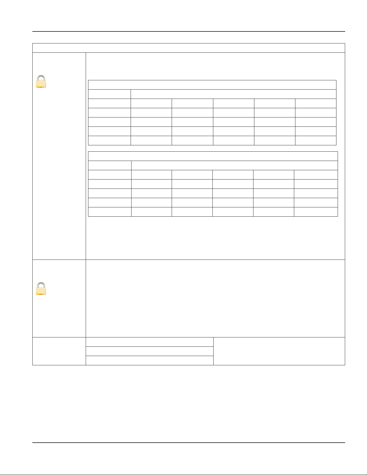
Unit Multiplier
[Off ]
Installation & Operation Manual
Advanced Features
The Unit Multiplier establishes the number of units of measure that have to accumulate before the
display totalizers are updated. This is also known as setting the number of “dead” zeroes in the display
totalizer. For example:
U
Backlight Control
Unit Multiplier less than 1
Unit Multiplier Example
OFF 0.00000 USG 0.00012 USG 0.00123 USG 0.01234 USG 0.12345 USG
0.0001 0.0000 USG 0.0001 USG 0.0012 USG 0.0123 USG 0.1234 USG
0.001 0.000 USG 0.000 USG 0.001 USG 0.012 USG 0.123 USG
0.01 0.00 USG 0.00 USG 0.00 USG 0.01 USG 0.12 USG
0.1 0.0 USG 0.0 USG 0.0 USG 0.0 USG 0.1 USG
Unit Multiplier greater than or equal to 1
Unit Multiplier Example
OFF 0.00000 USG 1.23456 USG 12.34567 USG 123.4567 USG 1234.456 USG
1 0 USG 1 USG 12 USG 123 USG 1234 USG
10 0 USG 0 USG 10 USG 120 USG 1230 USG
100 0 USG 0 USG 0 USG 100 USG 1200 USG
1000 0 USG 0 USG 0 USG 0 USG 1000 USG
To change the Unit Multiplier, follow these steps from the Advanced menu:
1. Select Unit Multiplier to view the Unit Multiplier display.
2. Select the desired unit multiplier.
3. Press [E] to save the option and to return to the Advanced menu.
You can set the meter's backlight to: Always On, Always Off and Timed Off.
[Timed Off ]
U
Token Copy Configuration
When set to Timed Off, the backlight will automatically turn off after one minute of inactivity
(no buttons pressed). Pressing any button will turn the backlight on, but will not immediately
navigate the menu.
To change the backlight control, follow these steps from the Advanced menu:
1. Select Backlight Control to view the Backlight Control display.
2. Select the desired option.
3. Press [E] to save the option and to return to the Advanced menu.
Store to Token
Restore from Token
Refer to IOM-194-XX-EN for details on using the
Token Copy features.
Page 43 August 2012
Page 44

M-Series® M2000 Electromagnetic Flow Meter
ADE Protocol Type The protocol type enables the ADE interface.
Selecting S1 or S2 will automatically configure
the Digital Input and Digital Output #1 for ADE
operation. Manually configuring the input and
output for ADE operation is not allowed and will
result in a on-screen error.
See "ADE Interface" on page 52 for further
details.
S1 – Standard ADE protocol
S2 – Enhanced ADE protocol, provides additional
digital information
Disabled – disables and removed ADE
configuration
Dial Type 4 – 8 dials
Analog Calibrate Custom Settings
[Zero Scale: 0 mA]
[Full Scale: 0 mA]
S
Factory Settings
[Factory Set]
S
To set the analog calibration custom settings, follow these steps from the
Advanced menu:
1. Select Analog Calibrate to view the Analog Calibrate menu.
2. Select Custom Settings to view the Custom Settings display.
3. Select one of the following:
• Offset 4 mA
• Offset 20 mA
4. Configure desired offset.
5. Press [E] to save the option and to return to the Custom Settings menu.
6. Press [E] to return to the Analog Calibrate menu.
To change the analog calibration factory settings, follow these steps from the
Advanced menu:
1. Select Analog Calibrate to view the Analog Calibrate menu.
2. Select Factory Settings to view the Factory Settings display.
3. Select one of the following:
• Calibration Point A
• Calibration Point B
4. Set the calibration point to the measured output current.
5. Press [E] to save the option and to return to the Factory Settings menu.
6. Press [E] to return to the Analog Calibrate menu.
Page 44 August 2012
Page 45

Installation & Operation Manual
Advanced Features
Software Filter Description The software filter operates as an acceleration filter. This filter when configured
properly allows for filtering of fast changes in fluid flow. Generally, this filter is used
in applications having highly conductive fluids. This filter is intended to help provide
smoothing of the analog output and display fluctuations.
Activation
The Activation parameter setting enables or disables the software acceleration filter.
[Off ]
A
Filter Delay
[1]
A
Acceleration
Factor
[1]
A
To change the Activation setting, follow these steps from the Advanced menu:
1. Select Activation from the Advanced menu.
2. Select the desired setting.
3. Press [E] to save the option and to return to the Advanced menu.
The Filter Delay parameter lets you set the amount of time that the flow will be
held constant once the filter is activated. The filter is activated by an acceleration
component of the fluid exceeding the configured limit.
To change the Filter Delay follow these steps from the Advanced menu:
1. Select Filter Delay, from the Advanced menu.
2. Select the desired setting.
3. Press [E] to save the option and to return to the Advanced menu.
The Acceleration Factor parameter lets you set the maximum acceleration for a given
pipe diameter and is dependent on the excitation frequency. The maximum fluid
velocity is 12 m/s. The following equation defines the maximum fluid acceleration:
Acceleration(MAX) = Acceleration Factor * 12 m/s * Pipe Area * Excitation
Frequency / 1.5
If the realized fluid acceleration exceeds the configured maximum acceleration, fluid
flow will be held constant for the time set at the Filter Delay parameter.
To change the Acceleration Factor setting, follow these steps from the Advanced
menu:
1. Select Acceleration Factor from the Advanced menu.
2. Select the desired setting.
3. Press [E] to save the option and to return to the Advanced menu.
Page 45 August 2012
Page 46

M-Series® M2000 Electromagnetic Flow Meter
Software Filter Constant Flow
During normal flow conditions, there is always a non-zero acceleration component.
Advanced Features
[150 M3/Sec2]
A
Peak Detect
[0 M3/Sec2]
A
MDN Filter Description This software filter operates as a Median filter. This filter is very responsive and can
For example, if acceleration of the flow activates the filter, the meter will assume
constant flow for the duration of the filter delay time unless the flow returns within
limits.
Properly configured, this parameter will help offset excessive impacts of the filter
delay. The Constant Flow parameter lets you set the acceleration limit for constant
flow.
To change the Constant Flow setting, follow these steps from the Advanced menu:
1. Select Constant Flow from the Advanced menu.
2. Select the desired setting.
3. Press [E] to save the option and to return to the Advanced menu.
Peak Detect offers a diagnostic view of the acceleration components observed
during flow conditions. This parameter records the “high water mark” of the
measured accelerations component. This value will help to properly configure the
Acceleration Factor parameter. Generally, you will set the acceleration factor at about
75% of the Peak Detect measurement.
To reset the Peak Detect setting, follow these steps from the Advanced menu:
1. Select Peak Detect from the Advanced menu.
2. Press [+] to reset.
3. Press [E] to return to the Advanced menu.
be used to help stabilize flow measurements. This filer is enabled by selecting a nonzero filter size. Supported filter sizes are:
• S5 - Size 5
• S7 - Size 7
• S9 - Size 9
The filter technique will use the median value of the last Sx samples used for
determining flow measurement.:
Page 46 August 2012
Page 47

Empty Pipe Cal.
EMPTY PIPE CALIBRATE
Volts = 3.00
> Cal [ON] E=OFF
Exit with Save
[Default]
S
Installation & Operation Manual
Advanced Features
Fluid conductivity impacts the performance of empty pipe measurements. If you require empty pipe
detection, you should perform this empty pipe calibration procedure.
Before starting the empty pipe calibration, verify that empty pipe detection is enabled. Also, run both
the empty pipe and the full pipe calibration procedures.
Calibrating an Empty Pipe
Before calibrating an empty pipe, verify that the pipe is empty.
To calibrate with an empty pipe, follow these steps from the Advanced menu:
1. Select Empty Pipe Cal to view the Calibration menus.
2. Select Cal. Empty Pipe to view the Empty Pipe Calibrate menu.
3. To enable calibration, place the cursor on the calibration enable line and press [E].
EMPTY PIPE CALIBRATE
Volts = 3.00
> Cal [ON] E=OFF
Exit with Save
4. Wait 30 seconds for voltage measurement to stabilize.
5. To save the setting, place the cursor on Exit with Save and press [E].
Calibrating a Full Pipe
Before calibrating a full pipe, verify that the pipe is full.
To calibrate with a full pipe, follow these steps from the Advanced menu:
1. Select Empty Pipe Cal to view the Calibration menus.
2. Select Cal. Full Pipe to view the Full Pipe Calibrate menu.
3. Enable calibration by placing the cursor on the calibration enable line and press [E].
FULL PIPE CALIBRATE
Volts = 1.515
> Cal [OFF] E=ON
Exit with Save
4. Wait 30 seconds for voltage measurement to stabilize.
5. To save the setting, place the cursor on Exit with Save and press [E].
Page 47 August 2012
Page 48

M-Series® M2000 Electromagnetic Flow Meter
Security Set Admin PIN
[00000]
Users logged in with this PIN will have access to all M2000 procedures.
To set the administrator's PIN, follow these steps from the Advanced Menu:
Advanced Features
A
Set Service PIN
[00000]
A
Set User PIN
[00000]
A
1. Select Security to view the Security menu.
2. Select Set Admin PIN to view the Admin PIN display.
3. Set the five-digit PIN number to the desired value.
4. Press [E] to save the PIN and to return to the Security menu.
Users logged in with this PIN will have access to all service level and user-level procedures.
Service users will not have access to administrative procedures.
To set the service PIN, follow these steps from the Advanced Menu:
1. Select Security to view the Security menu.
2. Select Set Service PIN to view the Service PIN display.
3. Set the five-digit PIN number to the desired value.
4. Press [E] to save the PIN and to return to the Security menu.
Users logged in with this PIN will have access to user-level procedures. User at this level
will not have access to administrative or service procedures.
To set the user's PIN, follow these steps from the Advanced Menu:
1. Select Security to view the Security menu.
2. Select Set User PIN to view the User PIN display.
3. Set the five-digit PIN number to the desired value.
4. Press [E] to save the PIN and to return to the Security menu.
Page 48 August 2012
Page 49

Error Counts
[0]
U
Installation & Operation Manual
Info/Help
Description This menu provides a diagnostic view of the meter’s performance. Below are several
system diagnostic counters and their definitions. Use discretion when interpreting
these counters. These values could be altered during system setup or when using
the verification device. We suggest that you reset these counters before you start
monitoring your system and look for conditions possibly affecting performance.
Detector The number of times an invalid detector condition has been observed.
Empty Pipe The number of times an empty pipe condition has been observed by the meter.
Full Scale The number of times the flow has exceeded the full scale flow setting.
Totalizer The number of times the totalizers have exceeded limits of the meter.
Pulse Sync. The number of times the pulse outputs have fallen out of synchronization.
ADC Interrupt The number of times an analog input measurement has been missed.
ADC Range The number of times the analog input measurement range has been exceeded.
System Error A diagnostic system message indicating the reason for a system reset.
System Resets The number of times the meter has been reset.
System Reset ID Diagnostic information about a system reset as a result of expired internal timers.
Token Errors Indicates the number of parameter copies from a memory token that failed to be copied
to the meter.
Page 49 August 2012
Page 50

M-Series® M2000 Electromagnetic Flow Meter
Rollover Counts
[0]
U
The number of times the totalizers have rolled over 9,999,999,999 (10 billion).
As the meter rolls over, a status indicator appears in the display. When this occurs, we suggest that
you record the totalizers and rollover counter and reset the totalizers. Resetting totalizers will also
clear the rollover counter.
For a meter configured in bidirectional mode, rollover is represented by the net totalizer (TN) as
“*********”. During this condition, the net totalizer (TN) can be calculated using the following
equation:
T(FWD) = [(ROLLOVERT+ x 10,000,000,000) + T+]
Info/Help
PowerUp Counter
[Not applicable]
U
Power Off Totalizer
[Not applicable]
U
Version Info
T(REV) = [(ROLLOVER
TN =T(FWD) – T(REV)
Where ROLLOVERTx is the rollover count for the appropriate totalizer
For a meter configured in unidirectional mode, the totalizer can be calculated using the following
equation:
T1 = [(ROLLOVERT1 x 10,000,000,000) + T1]
T2 = [(ROLLOVERT2 x 10,000,000,000) + T2]
Where ROLLOVERTx is the rollover count for the appropriate totalizer
The number of times that the unit has been powered on.
The length of time that the unit has been without power.
The current software version.
x 10,000,000,000) + T–]
T-
[Not applicable]
U
Serial Number
[Not applicable]
The manufacturing serial number in the format YYMM####.
Where YYMM indicates year and month of manufacturing and #### indicates the sequence number.
U
Page 50 August 2012
Page 51

Installation & Operation Manual
Info/Help
Meter Tag Name For PROFIBUS – This parameter is only programmable over external PROFIBUS communications.
Daughterboard
Information
Polarization Voltage Diagnostic voltage to help determine if the meter or application is performing optimally.
Restore Defaults
[Not applicable]
Describes current version of attached daughterboard.
OTE:N RS485 daughterboard is not recognized because it is a pass-through device rather than an
intelligent protocol converter like Hart-to-MODBUS.
Restores all non-calibrated parameters to the factory defaults.
A
Language Select
Language Select
[English]
U
The M2000 supports one alternate language along with English. This alternate language choice is
set at the factory. The options are: Spanish, German, Czech or French.
To select the language, follow these steps from the Language Select menu:
1. Select English or the Alternate Language.
2. Press [E] to save the selection.
Page 51 August 2012
Page 52

M-Series® M2000 Electromagnetic Flow Meter
ADE INTERFACE
This feature requires firmware version 1.10 or later. Reference Badger Meter P/N 6734-003 to obtain a firmware upgrade kit.
Enabling the meter as an ADE register requires three settings, all within the advanced menu, to be configured.
• Unit Multiplier – Selects the resolution of the display totalizer.
• Protocol Type – Selects the type of information to be transmitted to the ADE transmitter.
• Dial Type – Enables ADE and selects the number of significant totalizer digits to transmit.
Changing the dial type from Disabled will automatically configure the necessary digital inputs/outputs. It is not allowed to
manually change the digital inputs/outputs within the Input/Outputs menu. Below is a wiring diagram for connecting an ADE
transmitter to the meter.
ADE Connections
IMPORTANT: Remove jumper
JP1 before connecting transmitter
to meter
Output #1
COM
1
2
3
JP1
GREEN = DATA
BLACK = GND
Input
4
5
6
7
8
RED = CLOCK
9
10
11
12
13
14
Figure 20: ADE Interface
ADE Transmitter Cable
Page 52 August 2012
Page 53

Installation & Operation Manual
The following table demonstrates how the totalizers are displayed under various configurations of the Unit Multiplier (that is,
resolution) and Dial Type. The non-shaded digits are transmitted as defined by the dial type.
For example, if the dial type is 4-dial and the resolution is 10000 then an arbitrary totalizer value of 99999999 is displayed on
the meter as 99990000 and 9999 is transmitted to the receiving application. In this configuration it will take 10000 units (i.e.
USG) before the display totalizer is updated to a new value. For this example the display totalizer will rollover to 00000000.
Dial
Type
4 dial
5 dial
6 dial
7 dial
Unit Multiplier
(Resolution)
1 2 3 4 5 6 7 8 9 0
Display Digits
10000 1 2 3 4 0 0 0 0
1000 1 2 3 4 0 0 0
100 1 2 3 4 0 0
10 1 2 3 4 0
1 1 2 3 4
0.1 1 2 3 . 4
0.01 1 2 . 3 4
0.001 1 . 2 3 4
0.0001 0 0 1 2 3 4
10000 1 2 3 4 5 0 0 0 0
1000 1 2 3 4 5 0 0 0
100 1 2 3 4 5 0 0
10 1 2 3 4 5 0
1 1 2 3 4 5
0.1 1 2 3 4 . 5
0.01 1 2 3 . 4 5
0.001 1 2 . 3 4 5
0.0001 1 . 2 3 4 5
10000 1 2 3 4 5 6 0 0 0 0
1000 1 2 3 4 5 6 0 0 0
100 1 2 3 4 5 6 0 0
10 1 2 3 4 5 6 0
1 1 2 3 4 5 6
0.1 1 2 3 4 5 . 6
0.01 1 2 3 4 . 5 6
0.001 1 2 3 . 4 5 6
0.0001 1 2 . 3 4 5 6
10000 Not Applicable – Not enough display digits
1000 1 2 3 4 5 6 7 0 0 0
100 1 2 3 4 5 6 7 0 0
10 1 2 3 4 5 6 7 0
1 1 2 3 4 5 6 7
0.1 1 2 3 4 5 6 . 7
0.01 1 2 3 4 5 . 6 7
0.001 1 2 3 4 . 5 6 7
0.0001 1 2 3 . 4 5 6 7
Page 53 August 2012
Page 54

M-Series® M2000 Electromagnetic Flow Meter
Dial
Type
8 dial
It is important to understand that the totalizers will be represented in a manner equivalent to an actual ADE register. For
example, 1 USG on a 4 dial will be transmitted/displayed as “0001”. If in bidirectional mode, –1 USG will be transmitted/
displayed as “9999”.
The protocol type has two options:
• V1 – meter provides single totalizer, Tn (bi-directional) or T1 (uni-directional),
• V2 – meter provides extended information (For ORION SE or ORION ME)
The additional information provided by protocol type V2 is only accessible for specific models of the ADE transmitter (i.e.
ORION SE or ORION ME). The additional information of protocol type V2 includes, status information of the meter, meter
identification, a second totalizer reading (T+ or T2), relative flow rate (0…100%), and flow direction.
Unit Multiplier
(Resolution)
10000 Not Applicable – Not enough display digits
1000 Not Applicable – Not enough display digits
100 1 2 3 4 5 6 7 8 0 0
10 1 2 3 4 5 6 7 8 0
1 1 2 3 4 5 6 7 8
0.1 1 2 3 4 5 6 7 . 8
0.01 1 2 3 4 5 6 . 7 8
0.001 1 2 3 4 5 . 6 7 8
0.0001 1 2 3 4 . 5 6 7 8
1 2 3 4 5 6 7 8 9 0
Display Digits
STORE / RESTORE FEATURE
The Store/Restore feature is intended to save installation costs and reduce installation time. This feature is also intended to
protect meter configuration and assure the operator that the meter is properly configured. Over time and handling of the
meter, the meter configuration could change. The Store/Restore feature allows the meter to be quickly set to the operator’s
original configuration. Refer to the Store/Restore IOM for details on this feature.
DATA LOGGING FEATURE
The Data Logging feature records three types of events to a memory token:
• Totalizer/error events
• Configuration change events
• Startup events (power up, power down or reset events)
Each type of event is recorded into three separate files stored on the memory token. These files are extracted using the
provided flow meter tool software over the RS232 communication link. Refer to the Data Logging IOM for details on this
feature.
Page 54 August 2012
Page 55

Installation & Operation Manual
MAINTENANCE
Mandatory, routine or scheduled maintenance should not be required for the M2000 Mag Meter electronics or flow tube after
proper installation.
However, some instances may require personnel to perform the following:
• Flow tube and electrode cleaning
• Fuse replacement
• Circuit board replacement
• Disconnect main power to the unit before attempting any device maintenance or cleaning.
• Do not clean components inside the amplifier or junction box.
Cleaning the Flow Tube and Electrode
At times flow tube, electrodes, amplifier/junction box housings and the amplifier window may need periodic cleaning,
depending on process fluid properties, fluid flow rate and surrounding environment.
Clean the flow tube and electrodes by following the material handling and cleaning procedures documented in Material
Safety Data Sheet (MSDS) guidelines for the product(s) that were in contact with the flow tube and electrodes.
Should flow tube and/or electrode cleaning become necessary:
1. Disconnect detector from pipeline.
2. Clean electrodes according to MSDS guidelines.
3. Reconnect detector to pipeline.
Replacing the Fuse
Disconnect main power to the unit before attempting any device maintenance. Risk of electrical shock. Replace the fuse only
with 250V AC, 2 amp, slow blow (5 x 20 mm).
Authorized personnel must replace fuses.
Replacing the Circuit Board
Refer to the M-Series M2000 Interchangeability Procedure Application Brief for information on replacing circuit boards.
Page 55 August 2012
Page 56

M-Series® M2000 Electromagnetic Flow Meter
TROUBLESHOOTING
The M2000 mag meter is designed for many years of optimal performance. However, should it malfunction, there are certain
things that we recommend you check before contacting our Technical Support department or your local Badger Meter
Representative.
OTE:N If the fluid measured has a high concentration of conductive solids, deposits may accumulate on the internal
liner walls and electrodes. These deposits will cause a reduction of the measuring output. Thus, Badger Meter
recommends that you remove the meter and inspect the liner and electrodes after six months. If deposits are found,
remove them with a soft brush. Repeat inspection process every six months or until an appropriate inspection cycle
can be established for the specific application.
OTE:N Other general conditions include:
Description Possible Cause Recommended Action
Flow is present but display
is "0"
Inaccurate measuring Improper calibration.
No display No power.
Flow rate value known to be
wrong
Flow rate indication
unstable
Digital input is holding flow.
Disconnected signal cable.
Detector mounted opposite of the main
flow direction (see arrow on the nameplate).
Coil or electrode cables exchanged.
Improper low flow cutoff or full scale flow.
Wrong calibration parameter.
Pipe not fully filled, or air in pipe.
Invalid fluid conductivity.
Invalid fluid mixture.
Incorrect power.
Bad wiring connections.
Blown fuse.
Detector factor.
Deposits on electrodes and/or liner.
Incorrect pipe size programmed.
Cable issue.
Grounding issue.
Partially full pipe.
Air in pipe.
Amplifier location – outside electrical.
Invalid fluid conductivity.
Check signal cable.
Turn detector by 180° or switch terminal E1
and E2 or reprogram to bidirectional mode.
Check cable connections for cross wiring.
Verify digital input configuration.
Replace configuration defaults.
Restore calibration defaults.
Check the parameters (detector factor and
size) according to supplied data sheet.
Check if meter is completely filled with fluid.
Purge line to eliminate air bubbles.
Apply power.
Check power value.
Replace fuse (2 amp, 250V AC, slow blow
5 x 20 mm).
Check display ribbon cable.
Check value on label.
Check and remove deposits.
Check size if necessary.
Make sure cable is shielded and not vibrating.
Make sure meter is properly grounded to a
good earth ground.
Make sure pipe is full of fluid.
Make sure fluid does not contain air bubbles.
Make sure amplifier is not too close to sources
of electrical interference.
Page 56 August 2012
Page 57

Menu Manager Configuration Errors
Error Description Recommended Action
100 ADE: Configuration of the ADE
interface is invalid.
101 ADE: Enabling/Disabling ADE
operation is invalid
110 Output 1/2: Pulse Output
Configuration Error
120 Display: Totalizer Conversion
Error – Totalizer cannot be properly converted for display
121 Output 1/2: Pulse Output
Conguration Error
This error is displayed when an invalid modication to either of the following menu parameters is
detected: Protocol Type, Dial Type, Unit Multiplier, Digital Input Function Type or Digital Output Function Type.
1. Conguring the M2000 as an ADE interface has the following limitations, Protocol Type V1
is only allowed if number of dials is less than 8.
2. The resolution of the totalizers (i.e. Unit Multiplier) must be set to something other than
OFF.
3. For 8 dial conguration, a resolution of 10000 and 1000 are not supported. There are not
enough display digits to accommodate 8 dials and greater than 100 units of resolution.
4. For 7 dial conguration, a resolution of 10000 is not supported. There are not enough
display digits to accommodate 7 dials and greater than 1000 units of resolution.
This error is observed when Digital input or output function is manually selected for ADE operation.
Enabling or Disabling ADE operation can only be accomplished by setting the ADE protocol type.
This error is observed when improperly conguring either the full scale ow, pulse per unit, pulse
width or digital output function type for pulse output operation. Preparing these parameters for pulse
output operation (i.e. forward or reverse) has limitations that are monitored by the menu manager.
This error can indicate the following conguration violations:
1. Pulse Frequency exceeds limits at full scale ow
2. Pulse duty cycle is less than 50% at full scale ow (i.e. pulse on time > pulse o time)
3. AMR Pulse Frequency exceeds limit at full scale ow
The pulse frequency limit is 10 kHz when the pulse width is 0 (i.e. 50% duty cycle).
The pulse frequency limit is 1 / (2 * Pulse Width) when the pulse width is non-zero in order to achieve
a 50% duty cycle.
For AMR operation, the frequency limit is 3 HZ.
Follow these steps for configuring meter for pulse output operation:
1. Set PPU to zero for both output 1 and 2
2. If necessary, set full scale ow appropriately for application
3. Set PW as required by equipment receiving pulse transmissions from meter. Observe
frequency limits for non-zero pulse widths.
4. Determine the desired pulse frequency at a typical ow rate (i.e. 1000 HZ @ 250 GPM
5. Calculate ratio of typical ow rate to full scale ow: ratio = typical ow rate / full scale ow
(i.e. 250 GPM / 500 GPM = 0.5)
6. Calculate ow rate conversion factor: For GPM, conversion factor = 1/60, for GPH,
conversion factor = 1/3600, for GPS, conversion factor = 1
7. Calculate PPU: PPU = (Desired pulse frequency at typical ow rate / ratio) / [ Full Scale Flow
* (conversion factor) ]= (1000 / 0.5) / [500 * (1/60) ] = 240 Pulse / Gallon
8. If an error is received consider reducing value of full scale ow and ensuring desired pulse
frequency is within limits. Then redo steps 4-7
If not using the pulse outputs, set the pulses per unit to zero to allow for reconfiguration of the
full scale flow. If it is required to use the pulse outputs, re-evaluate the pulse output configuration.
Consider recording and clearing totalizers following pulse output configuration"
This error is observed while trying to change the totalizer units. Limits of display will prevent
improper conguration of the volume unit dependent on current totalizer values. Consider
recording and cleaning totalizers prior to changing totalizer.
This error is observed when changing the totalizer units of measure. This error implies the pulse
conguration exceeds limits (see error 110). Please note the pulses per unit is not automatically
updated on volume unit reconguration. The pulses per unit should be manually changed to
accommodate the desired units of measure. It may be necessary to set the pulses per unit to zero then
change to the desired totalizer units.
Installation & Operation Manual
Page 57 August 2012
Page 58

M-Series® M2000 Electromagnetic Flow Meter
Menu Manager Configuration Errors
Error Description Recommended Action
140 Output 3: Conguration Error – Full
scale frequency exceeds limits of
relay (1000 Hz)
150 Output 3: Conguration Error – Full
scale frequency exceeds limits (10
kHz)
170 Output 1/2: Output Type
Configuration Error
171 Output 1/2: Output Type
Configuration Error
190 Full Scale Flow: Entered Value
exceeds limits
Reduce full scale frequency setting of output when hardware is congured for relay operation.
Reduce full scale frequency setting of output when hardware is congured for open collector
operation.
This error is observed when the function type is 24V DC and the output type is changed from
Normally Open to Normally Closed. It is required for 24V DC output operation that the output type be
Normally Open.
This error is observed when the function type is ADE and the output type is changed from Normally
Open to Normally Closed. It is required for ADE operation that the output type be Normally Open
Value entered exceeds the absolute maximum flow the meter supports. Reduce the value for this
parameter or consider increasing pipe diameter.
Display Error / Status Messages
Error Message Possible Cause Recommended Action
Err: Detector No detector connection with amplier. Check detector and cable connections in accordance with this manual.
Connection between amplier and detector Contact Technical Support.
Supply voltage too low. Contact Technical Support.
Grounded coils in meter. Contact Technical Support.
Water in detector. Contact Technical Support.
Err: Empty pipe Pipe may not be full. Make sure all trapped air is out of system.
Err: Full scale Actual ow rate is exceeding programmed ow. Reduce ow rate or increase the programmed full scale value by more than 5%.
Err: AD-Range AD-Converter is exceeding signal limits. Check the grounding scheme of the meter installation. See grounding section in this
Err: AD-INT Initialization of AD-Converter unsuccessful. Contact Technical Support.
Err: Rollover Rollover counters have exceeded limit. Clear all totalizers.
Err: Rollover Status Totalizer rollover has occurred. Reload totalizer then clear all totalizers.
Err: Simulation I/O simulator is enabled. Disable simulator in I/O menu.
If uid or uid conductivity recalibrate the parameter.
manual. Verify pipe is not empty.
Page 58 August 2012
Page 59

INTENTIONAL BLANK PAGE
Installation & Operation Manual
Page 59 August 2012
Page 60

M-Series and ORION are registered trademarks of Badger Meter, Inc. Other trademarks appearing in this document are the property of their respective entities.
Due to continuous research, product improvements and enhancements, Badger Meter reserves the right to change product or system specications without notice, except to the extent an outstanding
contractual obligation exists. © 2012 Badger Meter, Inc. All rights reserved.
www.badgermeter.com
The Americas | Badger Meter | 4545 West Brown Deer Rd | PO Box 245036 | Milwaukee, WI 53224-9536 | 800-876-3837 | 414-355-0400
México | Badger Meter de las Americas, S.A. de C.V. | Pedro Luis Ogazón N°32 | Esq. Angelina N°24 | Colonia Guadalupe Inn | CP 01050 | México, DF | México | +52-55-5662-0882
Europe, Middle East and Africa | Badger Meter Europa GmbH | Nurtinger Str 76 | 72639 Neuffen | Germany | +49-7025-9208-0
Czech Republic | Badger Meter Czech Republic s.r.o. | Maříkova 2082/26 | 621 00 Brno, Czech Republic | +420-5-41420411
Slovakia | Badger Meter Slovakia s.r.o. | Racianska 109/B | 831 02 Bratislava, Slovakia | +421-2-44 63 83 01
Asia Pacific | Badger Meter | 80 Marine Parade Rd | 21-04 Parkway Parade | Singapore 449269 | +65-63464836
China | Badger Meter | Rm 501, N° 11 Longyue Apartment | N° 180 Longjin Rd, Jiuting Songjiang District | Shanghai, China | 201615 | +86-21-5763 5412
 Loading...