

Page 1

M-Series® M1000
Electromagnetic Flow Meter
MAG-UM-00379-EN-04 (January 2018)
User Manual
Page 2

M-Series® M1000, Electromagnetic Flow Meter
Page ii January 2018MAG-UM-00379-EN-04
Page 3

User Manual
CONTENTS
Safety Precautions and Instructions. . . . . . . . . . . . . . . . . . . . . . . . . . . . . . . . . . . . . . . . . . . . . . . . . . . . . . . . . . 5
System Description . . . . . . . . . . . . . . . . . . . . . . . . . . . . . . . . . . . . . . . . . . . . . . . . . . . . . . . . . . . . . . . . . . . . 5
Approvals . . . . . . . . . . . . . . . . . . . . . . . . . . . . . . . . . . . . . . . . . . . . . . . . . . . . . . . . . . . . . . . . . . . . . . . . . . 6
Unpacking and Inspection . . . . . . . . . . . . . . . . . . . . . . . . . . . . . . . . . . . . . . . . . . . . . . . . . . . . . . . . . . . . . . . 6
Rigging, Lifting and Moving Large Units . . . . . . . . . . . . . . . . . . . . . . . . . . . . . . . . . . . . . . . . . . . . . . . . . . . . 6
Meter Location, Orientation and Applications . . . . . . . . . . . . . . . . . . . . . . . . . . . . . . . . . . . . . . . . . . . . . . . . . . . 8
Temperature Ranges . . . . . . . . . . . . . . . . . . . . . . . . . . . . . . . . . . . . . . . . . . . . . . . . . . . . . . . . . . . . . . . . 8
Remote Amplier Outdoor Location . . . . . . . . . . . . . . . . . . . . . . . . . . . . . . . . . . . . . . . . . . . . . . . . . . . . . . 8
Pipelines and Fluid Flow . . . . . . . . . . . . . . . . . . . . . . . . . . . . . . . . . . . . . . . . . . . . . . . . . . . . . . . . . . . . . . 9
Meter Orientation . . . . . . . . . . . . . . . . . . . . . . . . . . . . . . . . . . . . . . . . . . . . . . . . . . . . . . . . . . . . . . . . . . 9
Straight Pipe Requirements . . . . . . . . . . . . . . . . . . . . . . . . . . . . . . . . . . . . . . . . . . . . . . . . . . . . . . . . . . . 10
Pipe Reducer Requirements . . . . . . . . . . . . . . . . . . . . . . . . . . . . . . . . . . . . . . . . . . . . . . . . . . . . . . . . . . . 10
Chemical Injection Applications . . . . . . . . . . . . . . . . . . . . . . . . . . . . . . . . . . . . . . . . . . . . . . . . . . . . . . . . 10
Partially-Filled Pipe Situations. . . . . . . . . . . . . . . . . . . . . . . . . . . . . . . . . . . . . . . . . . . . . . . . . . . . . . . . . . 11
Amplier Mounting Conguration Options . . . . . . . . . . . . . . . . . . . . . . . . . . . . . . . . . . . . . . . . . . . . . . . . . . . . 12
Meter Mount Conguration . . . . . . . . . . . . . . . . . . . . . . . . . . . . . . . . . . . . . . . . . . . . . . . . . . . . . . . . . . . 12
Remote Mount Conguration. . . . . . . . . . . . . . . . . . . . . . . . . . . . . . . . . . . . . . . . . . . . . . . . . . . . . . . . . . 12
Submersible Option . . . . . . . . . . . . . . . . . . . . . . . . . . . . . . . . . . . . . . . . . . . . . . . . . . . . . . . . . . . . . . . . 12
Protection Class . . . . . . . . . . . . . . . . . . . . . . . . . . . . . . . . . . . . . . . . . . . . . . . . . . . . . . . . . . . . . . . . . . 13
Meter Gaskets and Grounding . . . . . . . . . . . . . . . . . . . . . . . . . . . . . . . . . . . . . . . . . . . . . . . . . . . . . . . . . . . . 14
Meter/Pipeline Connection Gaskets . . . . . . . . . . . . . . . . . . . . . . . . . . . . . . . . . . . . . . . . . . . . . . . . . . . . . . 14
Meter Grounding . . . . . . . . . . . . . . . . . . . . . . . . . . . . . . . . . . . . . . . . . . . . . . . . . . . . . . . . . . . . . . . . . 14
Conductive Pipe Grounding. . . . . . . . . . . . . . . . . . . . . . . . . . . . . . . . . . . . . . . . . . . . . . . . . . . . . . . . . . . 14
Pipelines with Cathodic Protection . . . . . . . . . . . . . . . . . . . . . . . . . . . . . . . . . . . . . . . . . . . . . . . . . . . . . . 14
Non-Conductive Pipe Grounding . . . . . . . . . . . . . . . . . . . . . . . . . . . . . . . . . . . . . . . . . . . . . . . . . . . . . . . 15
Power Connections . . . . . . . . . . . . . . . . . . . . . . . . . . . . . . . . . . . . . . . . . . . . . . . . . . . . . . . . . . . . . . . . . . . 15
Wiring Safety . . . . . . . . . . . . . . . . . . . . . . . . . . . . . . . . . . . . . . . . . . . . . . . . . . . . . . . . . . . . . . . . . . . . 15
Opening the M1000 Cover. . . . . . . . . . . . . . . . . . . . . . . . . . . . . . . . . . . . . . . . . . . . . . . . . . . . . . . . . . . . 16
Auxiliary Power . . . . . . . . . . . . . . . . . . . . . . . . . . . . . . . . . . . . . . . . . . . . . . . . . . . . . . . . . . . . . . . . . . . 16
Remote Version. . . . . . . . . . . . . . . . . . . . . . . . . . . . . . . . . . . . . . . . . . . . . . . . . . . . . . . . . . . . . . . . . . . 17
Conguring Input/Output (I/O). . . . . . . . . . . . . . . . . . . . . . . . . . . . . . . . . . . . . . . . . . . . . . . . . . . . . . . . . 18
M1000 Main Menu Programming Options . . . . . . . . . . . . . . . . . . . . . . . . . . . . . . . . . . . . . . . . . . . . . . . . . . . . 19
Screen Layout. . . . . . . . . . . . . . . . . . . . . . . . . . . . . . . . . . . . . . . . . . . . . . . . . . . . . . . . . . . . . . . . . . . . 19
Function Buttons. . . . . . . . . . . . . . . . . . . . . . . . . . . . . . . . . . . . . . . . . . . . . . . . . . . . . . . . . . . . . . . . . . 19
Page iii January 2018 MAG-UM-00379-EN-04
Page 4

M-Series® M1000, Electromagnetic Flow Meter
Setting Personal Identication Numbers (PINs). . . . . . . . . . . . . . . . . . . . . . . . . . . . . . . . . . . . . . . . . . . . . . . 20
Menu Hierarchy Structure . . . . . . . . . . . . . . . . . . . . . . . . . . . . . . . . . . . . . . . . . . . . . . . . . . . . . . . . . . . . 21
Meter Setup Menu. . . . . . . . . . . . . . . . . . . . . . . . . . . . . . . . . . . . . . . . . . . . . . . . . . . . . . . . . . . . . . . . . 22
Measurement Menu. . . . . . . . . . . . . . . . . . . . . . . . . . . . . . . . . . . . . . . . . . . . . . . . . . . . . . . . . . . . . . . . 23
Input/Outputs Menu . . . . . . . . . . . . . . . . . . . . . . . . . . . . . . . . . . . . . . . . . . . . . . . . . . . . . . . . . . . . . . . 25
Totals Menu . . . . . . . . . . . . . . . . . . . . . . . . . . . . . . . . . . . . . . . . . . . . . . . . . . . . . . . . . . . . . . . . . . . . . 27
Communication Menu . . . . . . . . . . . . . . . . . . . . . . . . . . . . . . . . . . . . . . . . . . . . . . . . . . . . . . . . . . . . . . 28
Miscellaneous Menu . . . . . . . . . . . . . . . . . . . . . . . . . . . . . . . . . . . . . . . . . . . . . . . . . . . . . . . . . . . . . . . 29
Information Menu . . . . . . . . . . . . . . . . . . . . . . . . . . . . . . . . . . . . . . . . . . . . . . . . . . . . . . . . . . . . . . . . . 29
PIN Menu. . . . . . . . . . . . . . . . . . . . . . . . . . . . . . . . . . . . . . . . . . . . . . . . . . . . . . . . . . . . . . . . . . . . . . . 30
Login Screen . . . . . . . . . . . . . . . . . . . . . . . . . . . . . . . . . . . . . . . . . . . . . . . . . . . . . . . . . . . . . . . . . . . . 30
Maintenance . . . . . . . . . . . . . . . . . . . . . . . . . . . . . . . . . . . . . . . . . . . . . . . . . . . . . . . . . . . . . . . . . . . . . . . 30
Cleaning the Flow Tube and Electrode . . . . . . . . . . . . . . . . . . . . . . . . . . . . . . . . . . . . . . . . . . . . . . . . . . . . 30
Troubleshooting . . . . . . . . . . . . . . . . . . . . . . . . . . . . . . . . . . . . . . . . . . . . . . . . . . . . . . . . . . . . . . . . . . . . . 31
Errors & Warnings . . . . . . . . . . . . . . . . . . . . . . . . . . . . . . . . . . . . . . . . . . . . . . . . . . . . . . . . . . . . . . . . . 31
LED Status Indicators . . . . . . . . . . . . . . . . . . . . . . . . . . . . . . . . . . . . . . . . . . . . . . . . . . . . . . . . . . . . . . . 32
Connecting an ORION ADE Endpoint to the M1000 Meter . . . . . . . . . . . . . . . . . . . . . . . . . . . . . . . . . . . . . . . . . . 33
Wiring. . . . . . . . . . . . . . . . . . . . . . . . . . . . . . . . . . . . . . . . . . . . . . . . . . . . . . . . . . . . . . . . . . . . . . . . . 33
Programming . . . . . . . . . . . . . . . . . . . . . . . . . . . . . . . . . . . . . . . . . . . . . . . . . . . . . . . . . . . . . . . . . . . . 33
Specications. . . . . . . . . . . . . . . . . . . . . . . . . . . . . . . . . . . . . . . . . . . . . . . . . . . . . . . . . . . . . . . . . . . . . . . 34
Page iv January 2018MAG-UM-00379-EN-04
Page 5

Safety Precautions and Instructions
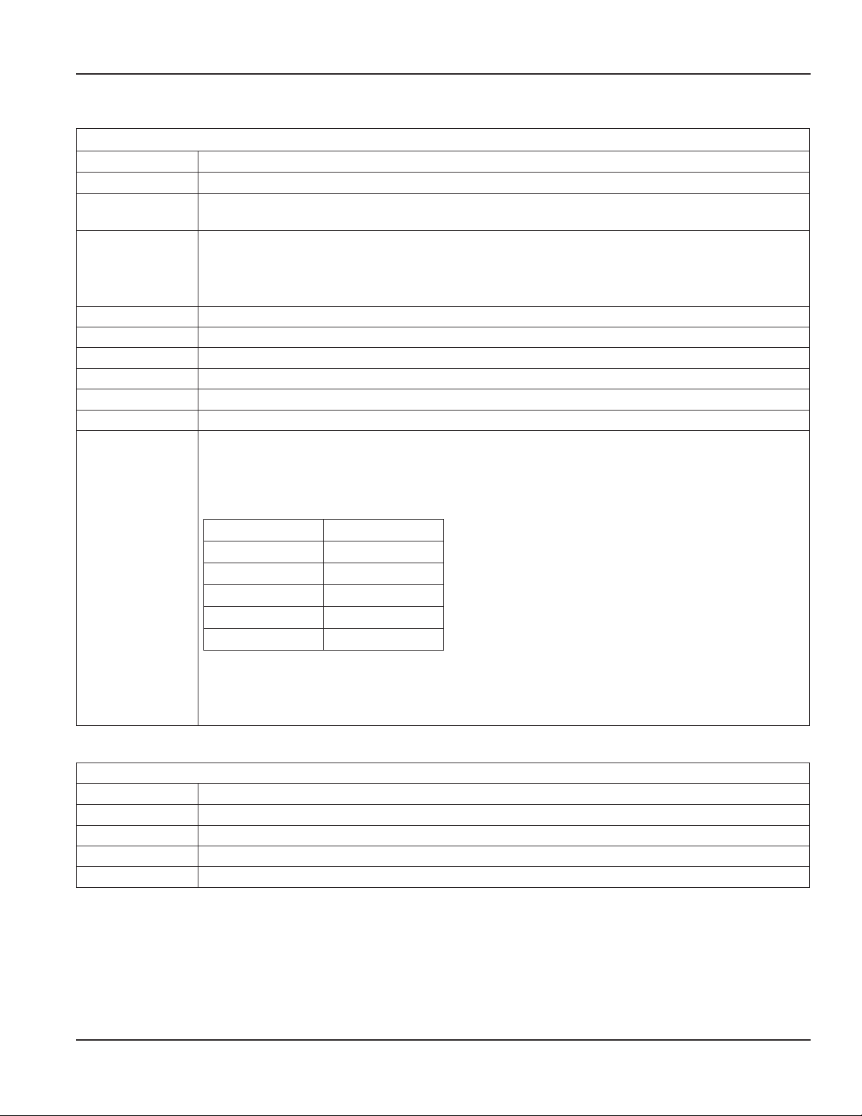
SAFETY PRECAUTIONS AND INSTRUCTIONS
Some procedures in this manual require special safety considerations. In such cases, the text is emphasized with the
following symbols:
Symbol Explanation
Warning indicates the potential for severe personal injury, death or substantial property damage.
Comply with the instructions and proceed with care.
Caution indicates the potential for minor personal injury or property damage. Comply with the
instructions and proceed with care.
IF THE EQUIPMENT IS USED IN A MANNER NOT SPECIFIED BY THE MANUFACTURER, THE PROTECTION PROVIDED BY
THE EQUIPMENT MAY BE IMPAIRED.
ATTENTION
UTILISER L'ÉQUIPEMENT DE MANIÈRE NON SPÉCIFIÉE PAR LE FABRICANT POURRAIT DIMINUER LA PROTECTION
ASSURÉE PAR L'ÉQUIPEMENT.
SYSTEM DESCRIPTION
The Badger Meter M-Series® Model M1000 electromagnetic flow meter is intended for fluid metering in most industries
including water, wastewater, food and beverage, pharmaceutical and chemical.
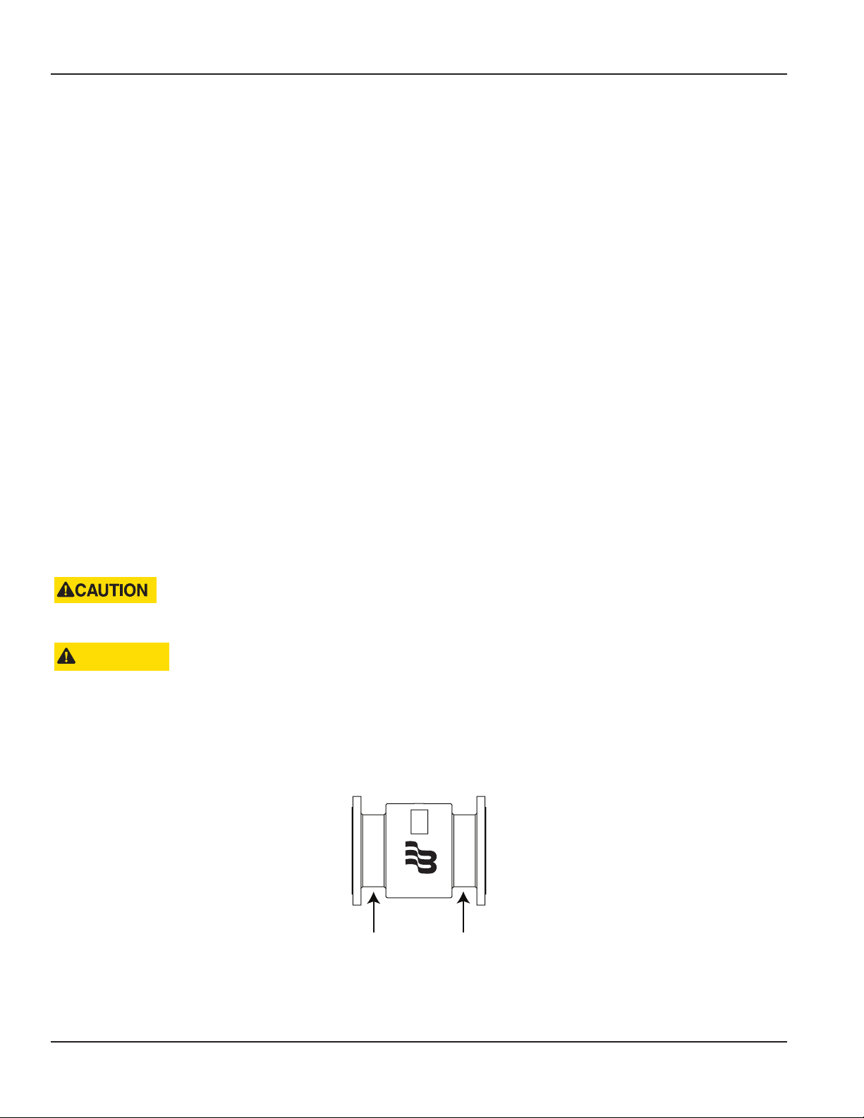
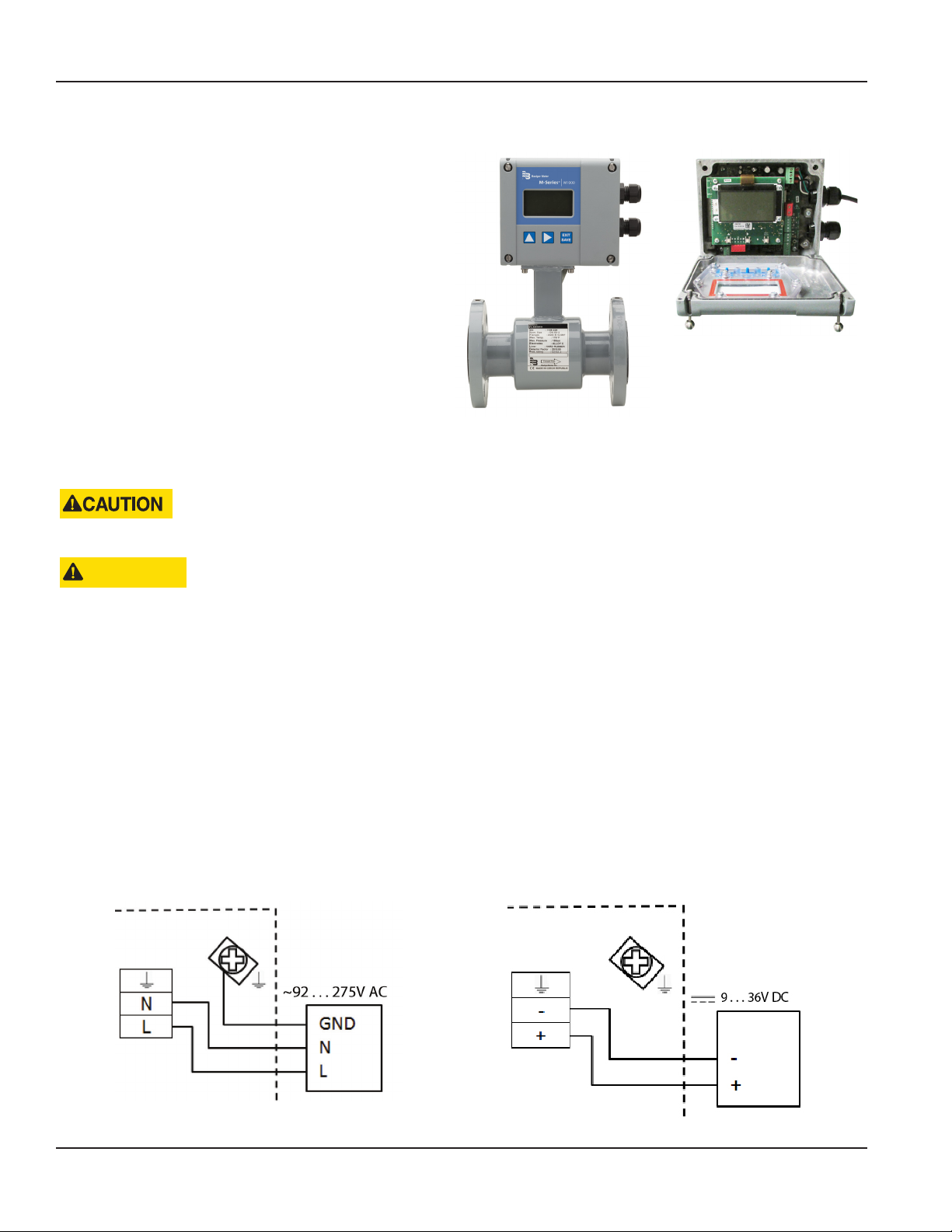
The basic components of an electromagnetic flow meter are:
• The detector, which includes the flow tube, isolating liner and measuring electrodes.
• The amplifier, which is the electronic device responsible for the signal processing, flow calculation, display and
output signals.
Amplifier
®
Figure 1: Amplifier and Detector
The construction materials of the wetted parts (liner and electrodes) should be appropriate for the specifications on the
intended type of service. We recommend that you review all of the compatibilities consistent with the specifications.
Each meter is factory tested and calibrated. A calibration certificate is included with each meter.
CONSULT THE INSTALLATION INSTRUCTIONS BEFORE DETERMINING THE TEMPERATURE RATING OF THE CABLE.
Detector
AVERTISSEMENT
CONSULTEZ LES INSTRUCTIONS D'INSTALLATION AVANT DE DÉTERMINER LES CARACTÉRISTIQUES THERMIQUES
DU CÂBLE.
MPORTANTI
Wire connections must meet or exceed a temperature rating of 80° C.
Page 5 January 2018 MAG-UM-00379-EN-04
Page 6
Approvals
APPROVALS
• UL Std. No. 61010-1 (2nd Edition)
Safety Requirements for Electrical Equipment for Measurement, Control, and Laboratory Use, Part 1: General Requirements
UNPACKING AND INSPECTION
Follow these guidelines when unpacking the M-Series equipment.
• If a shipping container shows any sign of damage, have the shipper present when you unpack the meter.
• Follow all unpacking, lifting and moving instructions associated with the shipping container.
• Open the container and remove all packing materials. Store the shipping container and packing
materials in the event the unit needs to be shipped for service.
• Verify that the shipment matches the packing list and your order form.
• Inspect the meter for any signs of shipping damage, scratches, or loose or broken parts.
OTE:N If the unit was damaged in transit, it is your responsibility to request an inspection report from the carrier within 48
hours. You must then file a claim with the carrier and contact Badger Meter for appropriate repairs or replacement.
• All detectors with polytetrafluoroethylene (PTFE) liners are shipped with a liner protector on each end to maintain proper
form of the PTFE material during shipping and storage.
OTE:N Do not remove the liner protectors until you are ready to install.
• Storage: If the meter is to be stored, place it in its original container in a dry, sheltered location. Storage temperature ranges
are: – 4…140° F (– 20…60° C).
Rigging, Lifting and Moving Large Units
WHEN RIGGING, LIFTING OR MOVING LARGE UNITS, FOLLOW THESE GUIDELINES:
ATTENTION
POUR LE GRÉEMENT, DU LEVAGE OU DU DÉPLACEMENT D'UNITÉS DE GRANDE TAILLE, VEUILLEZ SUIVRE CES
INSTRUCTIONS :
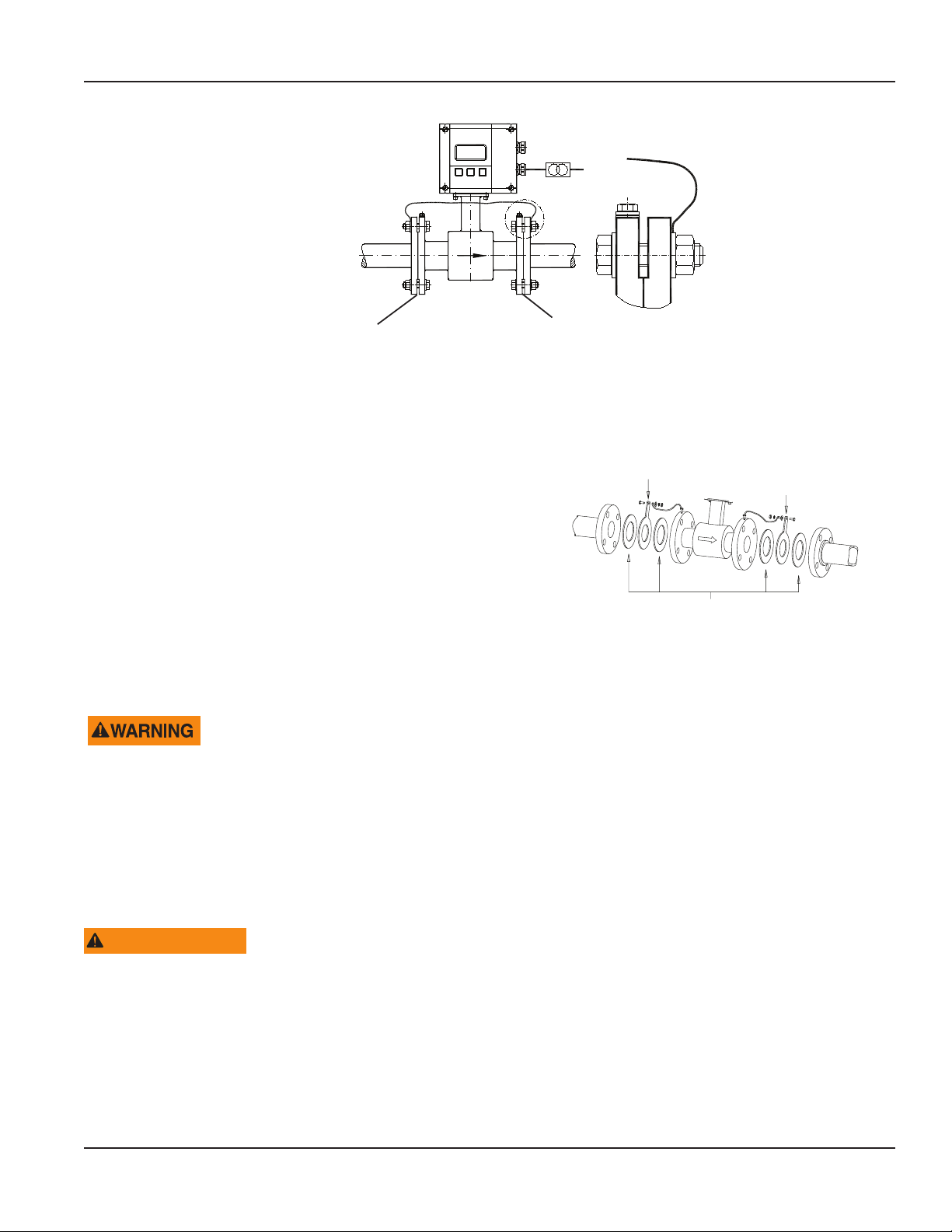
• DO NOT lift or move a meter by its amplifier, junction box, detector neck, or cables.
• Use a crane rigged with soft straps to lift and move meters with flow tubes that are between two inches and eight inches
(50 mm and 200 mm). Place the straps around the detector body, between the flanges, on each side of the detector.
®
Place straps between flanges.
Figure 2: Rigging Large Units
Page 6 January 2018MAG-UM-00379-EN-04
Page 7
Unpacking and Inspection
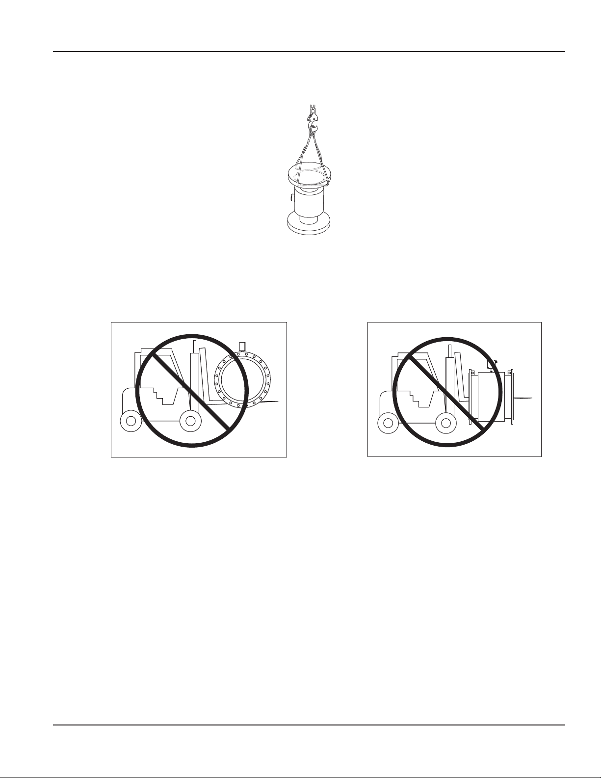
• Use the sling-rigged method to lift large detectors into a vertical position while they are still crated. Use this method to
position while they are still crated. Use this method to position large detectors vertically into pipelines.
Figure 3: Sling-Rigged Lifting Methods
• Do not lift a detector with a forklift by positioning the detector body on the forks, with the flanges extending beyond the
lift. This could dent the housing or damage the internal coil assemblies.
• Never place forklift forks, rigging chains, straps, slings, hooks or other lifting devices inside or through the detector's flow tube
to hoist the unit. This could damage the isolating liner.
Do not lift detector with forklift. Do not lift or rig lifting devices through detector.
Figure 4: Lifting and Rigging Cautions
Page 7 January 2018 MAG-UM-00379-EN-04
Page 8
Meter Location, Orientation and Applications
METER LOCATION, ORIENTATION AND APPLICATIONS
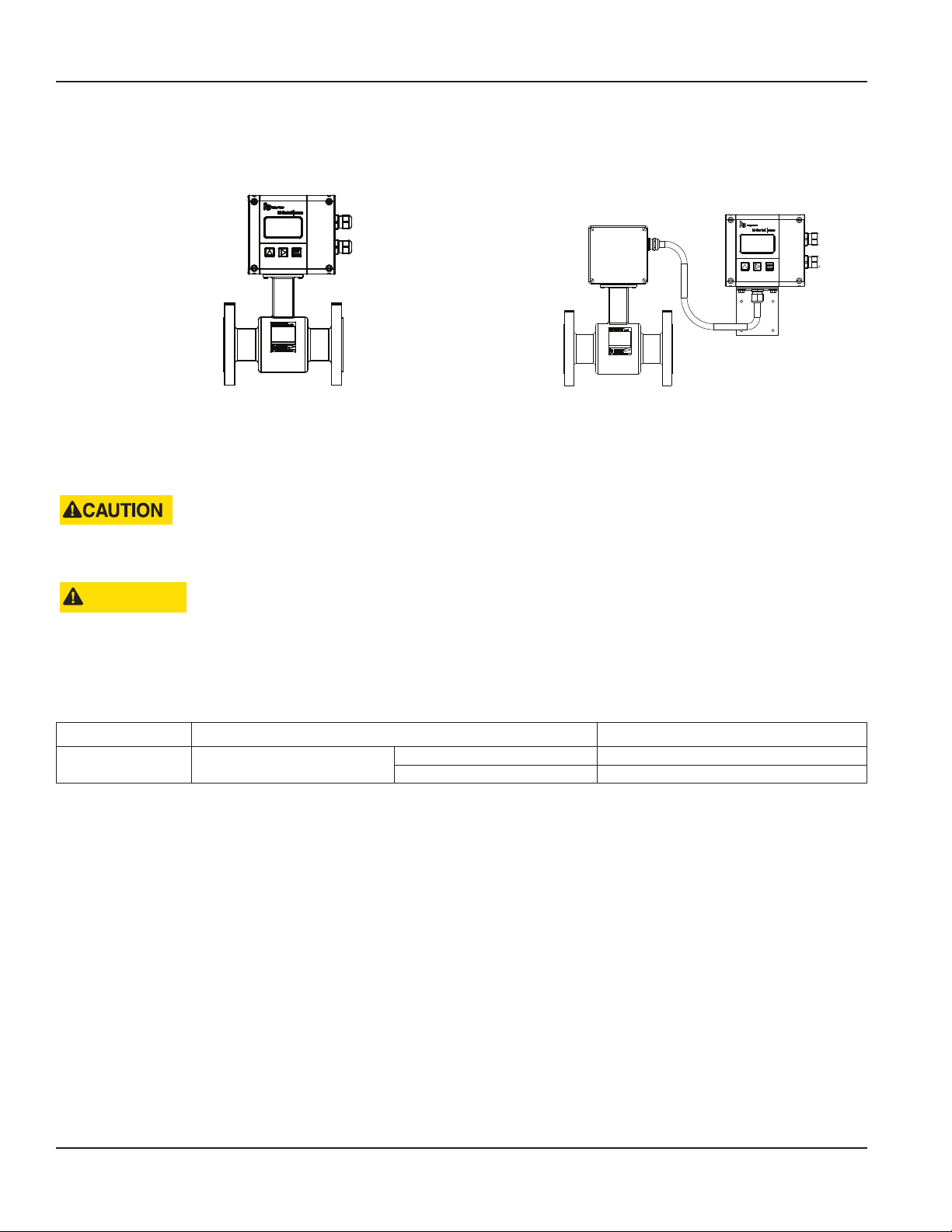
The M1000 provides two amplifier mounting options: an integral or meter mount option and a junction box/remote option.
Meter mount amplifier
Figure 5: Amplifier mounting options
Junction box with remote amplifier
Temperature Ranges
TO PREVENT DAMAGE TO THE METER, STRICTLY OBSERVE THE AMPLIFIER’S AND DETECTOR’S MAXIMUM
TEMPERATURE RANGES.
ATTENTION
AFIN D'ÉVITER TOUT DOMMAGE AU COMPTEUR, RESPECTEZ RIGOUREUSEMENT LES PLAGES DE TEMPÉRATURES
MAXIMALES DE L'AMPLIFICATEUR ET DU DÉTECTEUR.
• In regions with extremely high ambient temperatures, protect the detector.
• In cases where fluid temperature exceeds 212° F (100° C), use the remote version.
Amplifier Ambient temperature – 4…140° F (–20…60° C)
Detector Fluid temperature
PTFE / PFA – 40…302° F (– 40…150° C)
Hard rubber 32…176° F (0…80° C)
Remote Amplier Outdoor Location
The amplifier can be installed and operated outdoors. However, it must be protected from the elements, as follows:
• The ambient environment/temperature rating for the unit is – 4…140° F (–20…60° C).
• If an indoor location is within 150 feet (50 meters) of the detector, consider increasing the cable length and mounting the
amplifier indoors.
• At minimum, fabricate a roof or shield over and/or around the amplifier to protect the LCD display screen from direct
sunlight.
Page 8 January 2018MAG-UM-00379-EN-04
Page 9
RIGHT
Electrode
WRONG
Meter Location, Orientation and Applications
Pipelines and Fluid Flow
Take the following precautions during installation:
• Do not install the meter on pipes with extreme pipe vibrations. If pipes are vibrating, secure the piping with appropriate
pipe supports in front of and behind the meter. If vibrations cannot be restrained, mount the amplifier in a remote
location.
• Do not install the detector close to pipeline valves, fittings or impediments that can cause flow disturbances.
• For detectors with PTFE liners, do not install the detector on suction sides of pumps.
• Do not install the detector on outlet sides of piston or diaphragm pumps. Pulsating flow can affect meter performance.
• Avoid installing the detector near equipment that produces electrical interference such as electric motors, transformers,
variable frequency, and power cables.
• Verify that both ends of the signal cables are securely fastened.
• Place power cables and signal cables in separate conduits.
• Place the meter where there is enough access for installation and maintenance tasks.
Meter Orientation
Mag meters can operate accurately in any pipeline orientation and can measure volumetric flow in forward and reverse
directions.
OTE:N A "Forward Flow" direction arrow is printed on the detector label.
Vertical Placement
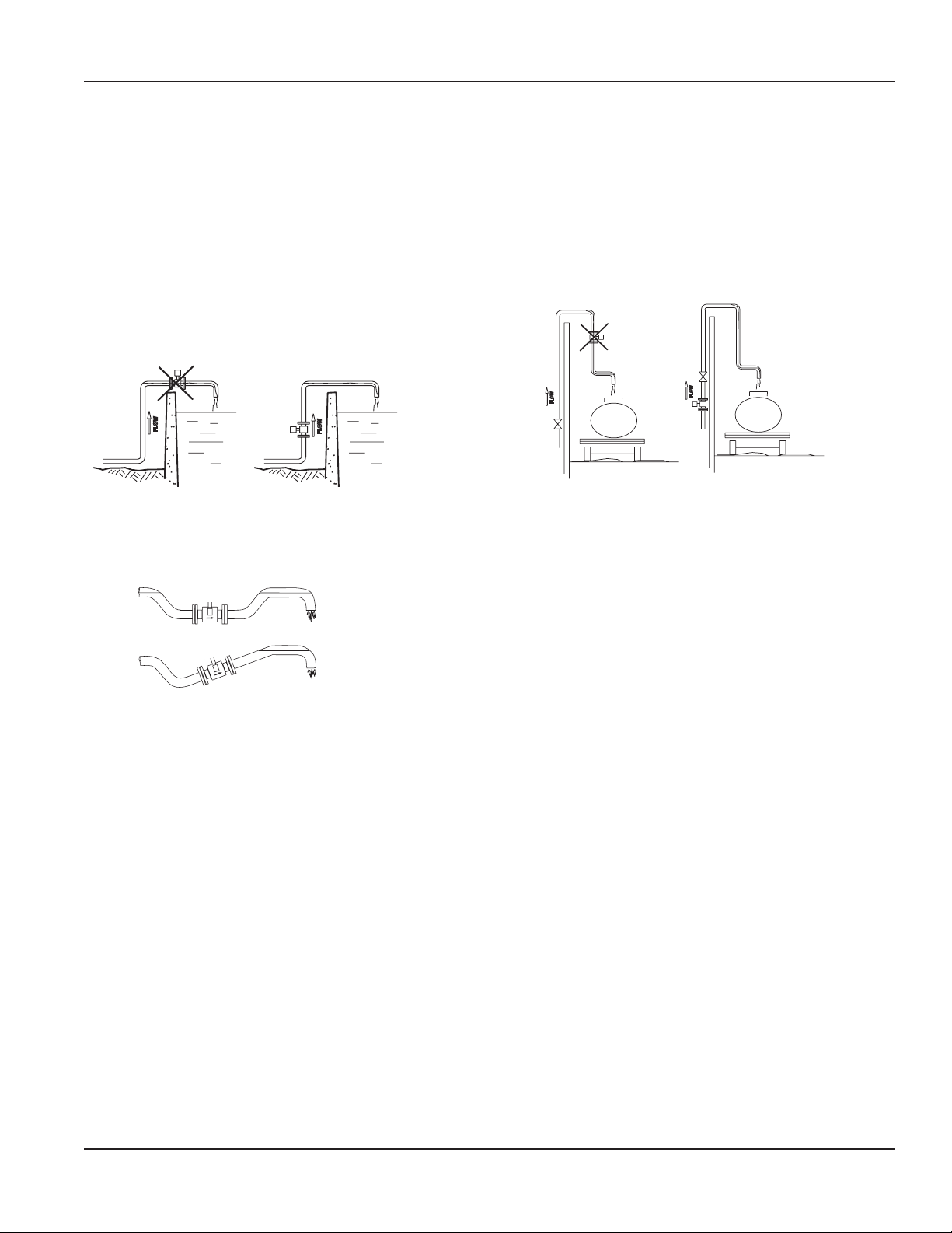
Mag meters perform best when placed vertically, with liquid flowing upward and meter electrodes in a closed, full pipe.
Figure 6: Vertical placement
Vertical placement allows the pipe to remain completely full, even in low flow, low pressure applications, and it prevents
solids build-up, sediment deposit and accumulation on the liner and electrodes.
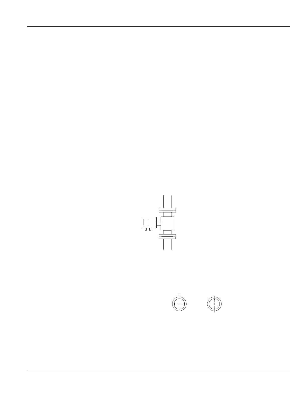
Horizontal Placement
M1000 meters are equipped with an Empty Pipe
Detection feature. If an electrode mounted in the pipe
is not covered by fluid for five seconds, the meter will
Electrode
Plane
Plane
display an Empty Pipe Detection condition. The meter
will send out an error message and stop measuring
flow. When the electrode is again covered with fluid,
the error message disappears and the meter will begin
Figure 7: Horizontal placement
measuring.
When installing the meter on a horizontal pipe, mount the detector to the pipe with the flow-measuring electrode axis in a
horizontal plane (three and nine o’clock). This placement helps prevent solids build-up, sediment deposit and accumulation
on the electrodes.
Page 9 January 2018 MAG-UM-00379-EN-04
Page 10

BUTTERFL
VE
FLOWMETER
Meter Location, Orientation and Applications
Straight Pipe Requirements
Sufficient straight-pipe runs are required at the
detector inlet and outlet for optimum meter accuracy
and performance. An equivalent of three diameters of
FORWARD FLOW
D (Pipe Size) D (Pipe Size)
straight pipe is required on the inlet (upstream) side. Two
diameters are required on the outlet (downstream) side.
CHECK VALVE
GLOBE VALVE
Y VALVE
PUMP
ELBOW
TEE
GATE VALVE
(FULLY OPEN)
MINIMUM STRAIGHT PIPE
3 x D
MINIMUM STRAIGHT PIPE
7 x D
MINIMUM PIPING REQUIREMENT
STANDARD CONCENTRIC
REDUCERS
(NO DISTANCE REQUIRED)
Figure 8: Straight pipe requirements
2 x D
MINIMUM STRAIGHT PIPE
ELBOW
TEE
ANY VAL
Pipe Reducer Requirements
With pipe reducers, a smaller meter can be mounted in larger pipelines. This arrangement may increase low-flow accuracy.
There are no special requirements for standard, concentric, pipe reducers.
Custom fabricated pipe reducers must have an approximate slope angle of 15 degrees to minimize flow disturbances and
excessive loss of head. If this is not possible, install the custom pipe reducers as if they were fittings and install the required
amount of straight pipe
Figure 9: Pipe reducer requirements
Chemical Injection Applications
For water line applications with a chemical injection point, install the meter upstream of the injection point. This eliminates
any meter performance issues.
Figure 10: Chemical injection point upstream of meter
If a meter must be installed downstream of a chemical injection connection, the distance between the meter and the
injection point should be between 50 and 100 feet (15 and 30 meters). The distance must be long enough to allow the water
or chemical solution to reach the meter in a complete, homogeneous mixture.
Figure 11: Chemical injection point upstream of meter
If the injection point is too close, the meter senses the two different conductivities for each liquid. This will likely result in
inaccurate measurements. The injection method—spaced bursts, continuous stream of drips or liquid or gas—can also affect
downstream readings by the meter.
Page 10 January 2018MAG-UM-00379-EN-04
Page 11
WRONG
RIGHT
Meter Location, Orientation and Applications
Partially-Filled Pipe Situations
In some locations, the process pipe may be momentarily only partially filled. Examples include: lack of back pressure,
insufficient line pressure and gravity flow applications.
To eliminate these situations:
• Do not install the meter at the highest point of the pipeline.
• Do not install the meter in a vertical, downward flow section of pipe.
• Always position the ON/OFF valves on the downstream side of the meter.
RIGHT
FLOW
Figure 12: Incorrect meter placement
WRONG
FLOW
FLOW
Do not install in a vertical, downward position. Position "On/Off" valves on downstream side.
Figure 13: Position valves on downstream side
FLOW
To minimize the possibility of partially-full pipe flows in horizontal, gravity or low pressure applications, create a pipe
arrangement that ensures the detector remains full of liquid at all times.
Figure 14: Pipe positioned to keep water in detector
Page 11 January 2018 MAG-UM-00379-EN-04
Page 12

Amplier Mounting Conguration Options
AMPLIFIER MOUNTING CONFIGURATION OPTIONS
There are two configuration options for mounting the amplifier. There are many options to accommodate a variety of
meter-placement and environmental conditions.
Meter Mount Conguration
The meter mount configuration has the amplifier mounted directly on the detector. This compact, self-contained
configuration minimizes installation wiring.
Remote Mount Conguration
The remote mount configuration places the amplifier at a location away from the fluid flow and detector. This is necessary in
situations where process fluid temperature or the environment exceeds amplifier ratings.
The detector and amplifier are connected by wires, run through conduit, between junction boxes on the detector and the
amplifier. The distance between the detector junction box and amplifier junction box can be up to 150 feet (50 meters). A
remote mounting bracket is supplied.
Submersible Option
If you are installing the meter in a vault, you should order the remote mount, submersible amplifier option. You must not
install the amplifier inside a vault. This will eliminate any potential problems resulting from humidity or temporary flooding in
the vault.
OTE:N The National Electronics Manufacturer's Association (NEMA) 6P enclosures are constructed for indoor or outdoor use
to provide protection against access to hazardous parts; to provide a degree of protection against ingress of solid
foreign objects and water (hose directed water and the entry of water during prolonged submersion at a limited
depth); that provide an additional level of protection against corrosion and that will be undamaged by the external
formation of ice on the enclosure.
Page 12 January 2018MAG-UM-00379-EN-04
Page 13

Amplier Mounting Conguration Options
Protection Class
In order to fulfill requirements of the protection class, follow these guidelines:
• BODY SEALS NEED TO BE UNDAMAGED AND IN PROPER CONDITION.
• ALL OF THE BODY SCREWS NEED TO BE FIRMLY TIGHTENED.
• OUTER DIAMETERS OF THE USED WIRING CABLES MUST CORRESPOND TO CABLE INLETS (FOR M20 Ø 5....13 MM). IN
CASES WHERE CABLE INLET IS NOT USED, PUT ON A DUMMY PLUG.
• TIGHTEN CABLE INLETS.
• IF POSSIBLE, LEAD CABLE AWAY DOWNWARDS. HUMIDITY CANNOT GET INTO CABLE INLET.
• WE NORMALLY DELIVER THE METER IN ACCORDANCE WITH PROTECTION CLASS IP 67. IF YOU HOWEVER REQUIRE A
HIGHER PROTECTION CLASS, THE AMPLIFIER IS TO BE INSTALLED SEPARATELY FROM THE DETECTOR. IF REQUESTED,
WE CAN ALSO DELIVER THE DETECTOR IN IP 68.
ATTENTION
• LES JOINTS DE CORPS NE DOIVENT PAS ÊTRE ENDOMMAGÉS ET ÊTRE EN BON ÉTAT.
• TOUTES LES VIS DE CORPS DOIVENT ÊTRE FERMEMENT SERRÉES.
• LE DIAMÈTRE EXTÉRIEUR DES FILS DE CÂBLAGE UTILISÉS DOIVENT CORRESPONDRE AUX ENTRÉES DE CÂBLE (POUR
M20 Ø 5... 13 MM). DANS LES CAS OÙ L'ENTRÉE DE CÂBLE N'EST PAS UTILISÉE, METTEZ UNE FICHE ISOLANTE.
• SERREZ LES ENTRÉES DE CÂBLE.
• SI CELA EST POSSIBLE, DIRIGEZ LE CÂBLE VERS LE BAS. ÉVITEZ QUE DE L'HUMIDITÉ NE PÉNÉTRE DANS L'ENTRÉE DE
CÂBLE.
• LE COMPTEUR OFFERT EST NORMALEMENT CONFORME À LA CLASSE DE PROTECTION IP 67. CEPENDANT, SI
VOUS EXIGEZ UNE CLASSE DE PROTECTION SUPÉRIEURE, L'AMPLIFICATEUR DOIT ÊTRE INSTALLÉ SÉPAREMENT DU
DÉTECTEUR. SUR DEMANDE, LE DÉTECTEUR PEUT ËTRE OFFERT EN IP 68.
Page 13 January 2018 MAG-UM-00379-EN-04
Page 14

GASKETS RECOMMENDED
Meter Gaskets and Grounding
METER GASKETS AND GROUNDING
Gasket and grounding requirements must be considered when determining the meter location, orientation and application.
Meter/Pipeline Connection Gaskets
You must install gaskets (not provided) between the detector's isolating liner
and the pipeline flange to ensure a proper and secure hydraulic seal. Use gaskets
that are compatible with the fluid. Center each gasket on the flange to avoid flow
restrictions or turbulence in the line.
During installation, do not use graphite or any electrically conductive sealing
compound to hold the gaskets. This could compromise the accuracy of the
measuring signal.
If you are using a grounding ring in the detector/pipeline connection, place the
ring between two gaskets. (See "Pipelines with Cathodic Protection" on page 14.)
Meter Grounding
Process pipeline material can be either electrically conductive (metal) or not electrically conductive (made of or lined with
PVC, fiberglass or concrete).
It is essential that the mag meter amplifier’s input ground (zero voltage reference) be electrically connected to the liquid media and
to a good, solid earth ground reference.
Conductive Pipe Grounding
Figure 15: Meter/pipeline connection gaskets
To achieve an adequate ground, the meter body MUST be electrically connected to the liquid media. The mag meter flanges
are provided with grounding bolts for this purpose.
If the pipe material is electrically conductive, simply install grounding straps between these grounding bolts and the
mating flanges.
To ensure a good electrical connection at the mating flanges, we recommend that you drill and tap the flanges and install a
grounding screw (not provided).
These grounding straps must be copper wire, at least 12 AWG size. They must be connected on both sides (inlet and outlet) of
the detector and to a local, earth ground.
Pipelines with Cathodic Protection
As for pipelines with cathodic protection, install meter potential-free. No electric connection from the meter to the pipeline
system may exist and power supply is to be provided via isolating transformer.
USE GROUNDING ELECTRODES GROUNDING RINGS ALSO NEED TO BE INSTALLED ISOLATED FROM THE
PIPELINE SYSTEM.
ATTENTION
UTILISEZ LES ÉLECTRODES DE MISE À LA TERRE LES ANNEAUX DE MISE À LA TERRE DOIVENT ÊTRE INSTALLÉES À
PARTIR DU SYSTÈME DE CONDUITES.
Observe national rules for potential-free installations.
Page 14 January 2018MAG-UM-00379-EN-04
Page 15
"X"
GASKETS RECOMMENDED
GROUNDING RING
"X"
Power Connections
M4:1
Electrically isolated
6 mm² Cu
Figure 16: Cathodic protection
Electrically isolated
Non-Conductive Pipe Grounding
If the process pipe is not electrically conductive (PVC, fiberglass, cement-lined pipes or any other non-conductive material) and the
meter was not originally ordered with an optional grounding electrode, you must install a pair of grounding rings between the
mating flanges at both ends of the meter. See the following illustration.
In this case, the grounding straps should be connected to both of the
grounding rings and to a good, solid earth ground. Grounding rings
GROUNDING RING
are available in stainless steel. If your fluid is too aggressive for stainless
steel, order a meter with the optional grounding electrode in a material
compatible with the fluid.
Figure 17: Non-conductive pipe grounding
POWER CONNECTIONS
Wiring Safety
AT INSTALLATION, BE SURE TO COMPLY WITH THE FOLLOWING REQUIREMENTS:
• Disconnect power to the unit before attempting any connection or service to the unit.
• Do not bundle or route signal lines with power lines.
• Keep all lines as short as possible.
• Use twisted pair shielded wire for all output wiring.
• Observe all applicable local electrical codes.
AVERTISSEMENT
LORS DE L'INSTALLATION, ASSUREZVOUS DE RESPECTER LES EXIGENCES SUIVANTES :
• Débranchez l'appareil avant d'essayer toute connexion ou tout service à l'appareil.
• Ne par regrouper ou acheminer les lignes de signaux aux lignes électriques.
• Gardez toutes les lignes aussi courtes que possible.
• Utilisez un câble blindé à paire torsadée pour tout le câblage de sortie.
• Respectez tous les codes locaux applicables en matière d'électricité.
Page 15 January 2018 MAG-UM-00379-EN-04
Page 16
Power Connections
Opening the M1000 Cover
The M1000 amplifier's design lets you open the cover
without completely removing it.
Follow these steps:
1. Completely remove the top two screws from the
amplier using a blade/slotted screwdriver.
2. Loosen both of the bottom screws so that the round
head of each screw clears the top face of the cover.
3. Pull down the cover to the open position.
• For the 2 x M20 cable inlets, use only flexible electric
cables.
• Use separate cable inlets for auxiliary power, signal and
input/output cables.
Figure 18: Remove two screws
Figure 19: Open the cover
Auxiliary Power
TO PREVENT ACCIDENTS, CONNECT MAIN POWER ONLY AFTER ALL OTHER WIRING HAS BEEN COMPLETED.
ATTENTION
AFIN D'ÉVITER LES ACCIDENTS, BRANCHEZ L'ALIMENTATION PRINCIPALE SEULEMENT UNE FOIS TOUT LE CÂBLAGE
COMPLÉTÉ.
Take national applicable rules into account.
• Observe type plate (mains voltage and frequency)
• Equipment shall be provided with a external means for disconnecting it from each operating energy supply source. The
disconnecting means shall disconnect all current-carrying conductors.
1. Open the cover (see "Opening the M1000 Cover" on page 16).
2. Push the auxiliary power cable through the upper cable inlet.
3. Connect as shown in Figure 20.
4. Close the cover and tighten the screws.
Power supply 92…275V AC (50/60 Hz)
Recommended cable size min. 0.75 mm²
Power supply 9…36V DC (13VA)
Recommended cable size min. 0.75 mm²
Figure 20: Auxiliary power connection
Page 16 January 2018MAG-UM-00379-EN-04
Page 17
Remote Version
CONNECT OR REMOVE THE SIGNAL CONNECTION CABLE ONLY
WHEN THE UNIT HAS BEEN SWITCHED OFF.
ATTENTION
BRANCHEZ OU RETIREZ LE CÂBLE DU SIGNAL DE CONNEXION
UNIQUEMENT LORSQUE L'APPAREIL EST ÉTEINT.
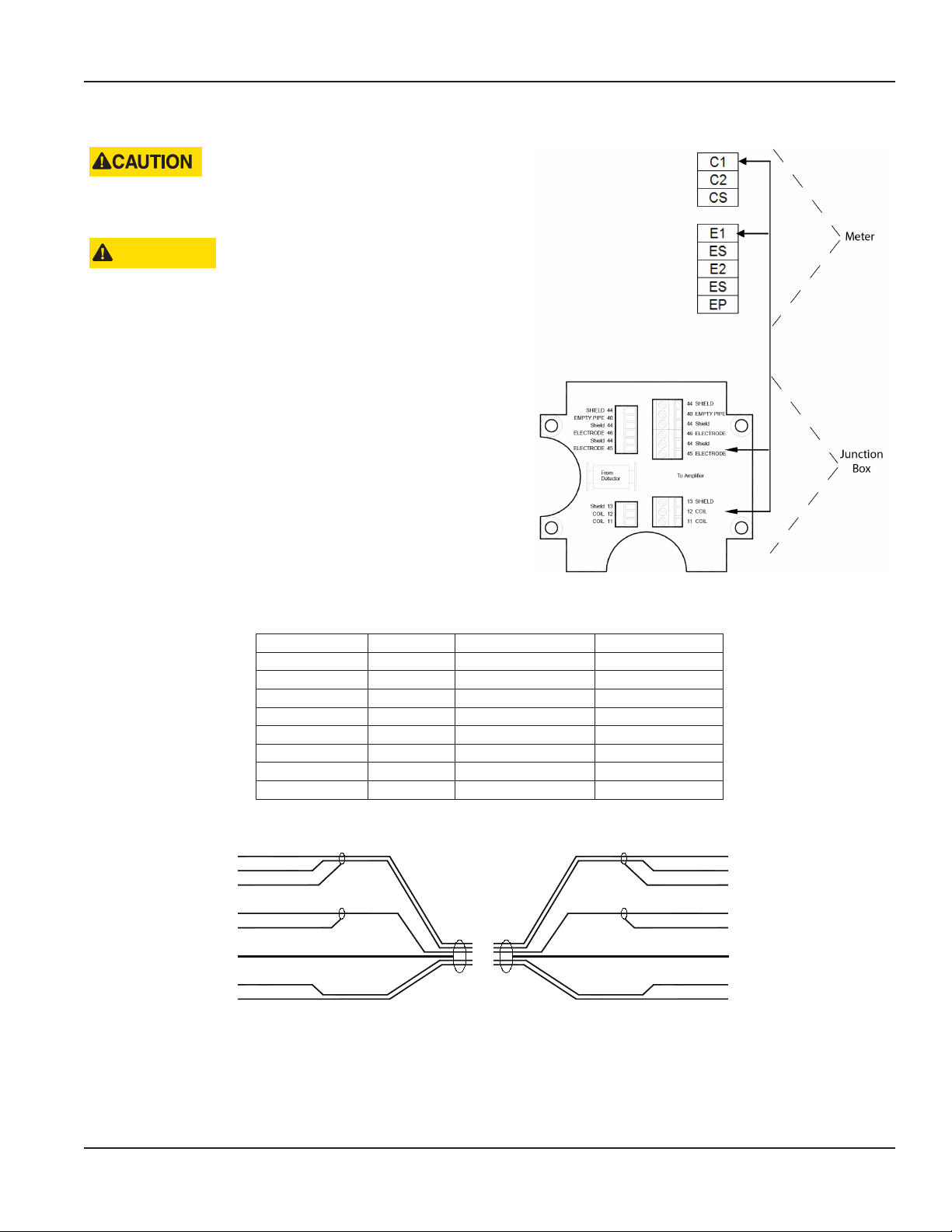
Connection to the Measuring Amplifier
1. Open the cover (see "Opening the M1000 Cover" on page 16).
2. Push the signal cable through the lower cable inlet.
3. Connect as shown in Figure 21.
4. Close the cover and tighten the screws and the wire gland.
Connection to the Junction Box
1. Open the junction box.
2. Push the signal cable through the upper cable inlet.
3. Connect as shown in Figure 21.
4. Close the cover and tighten the screws and wire gland.
Power Connections
Junction Box M1000 Description Wire Color
11 C1 Coil 1 Green
12 C2 Coil 2 Yellow
13 CS Main shield Yellow/Green
45 E1 Electrode 1 White
44* ES Electrode shield Black
46 E2 Electrode 2 Brown
40 EP Empty pipe Pink
44* ES Empty pipe shield Black
* Connections with number 44 are on the same potential.
white (45)
brown(46)
black (44)
pink (40)
black (44)
yellow/green (13)
yellow (12)
green (11)
5 . . . 50 m
Figure 22: Signal cable specification
Figure 21: Remote version connection
white (45)
brown (46)
black (44)
pink (40)
black (44)
yellow/green (13)
yellow (12)
green (11)
Page 17 January 2018 MAG-UM-00379-EN-04
Page 18
Power Connections
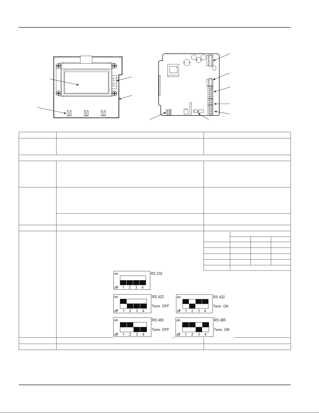
Conguring Input/Output (I/O)
Auxiliary power
Solid-state relays (Terminals S1, S2)
Digital input/output
(Terminals 1, 2, 3, 4, 5, 6)
Analog output (Terminals 7, 8, 9)
RS interface (Terminals A, B, Z, Y, G)
Display
Electrodes detector
Ethernet
USB port
S1
S2
1
2
3
4
5
6
7
8
9
A
B
C
Y
G
RS interface switchCoil detector
Figure 23: Configuring I/O
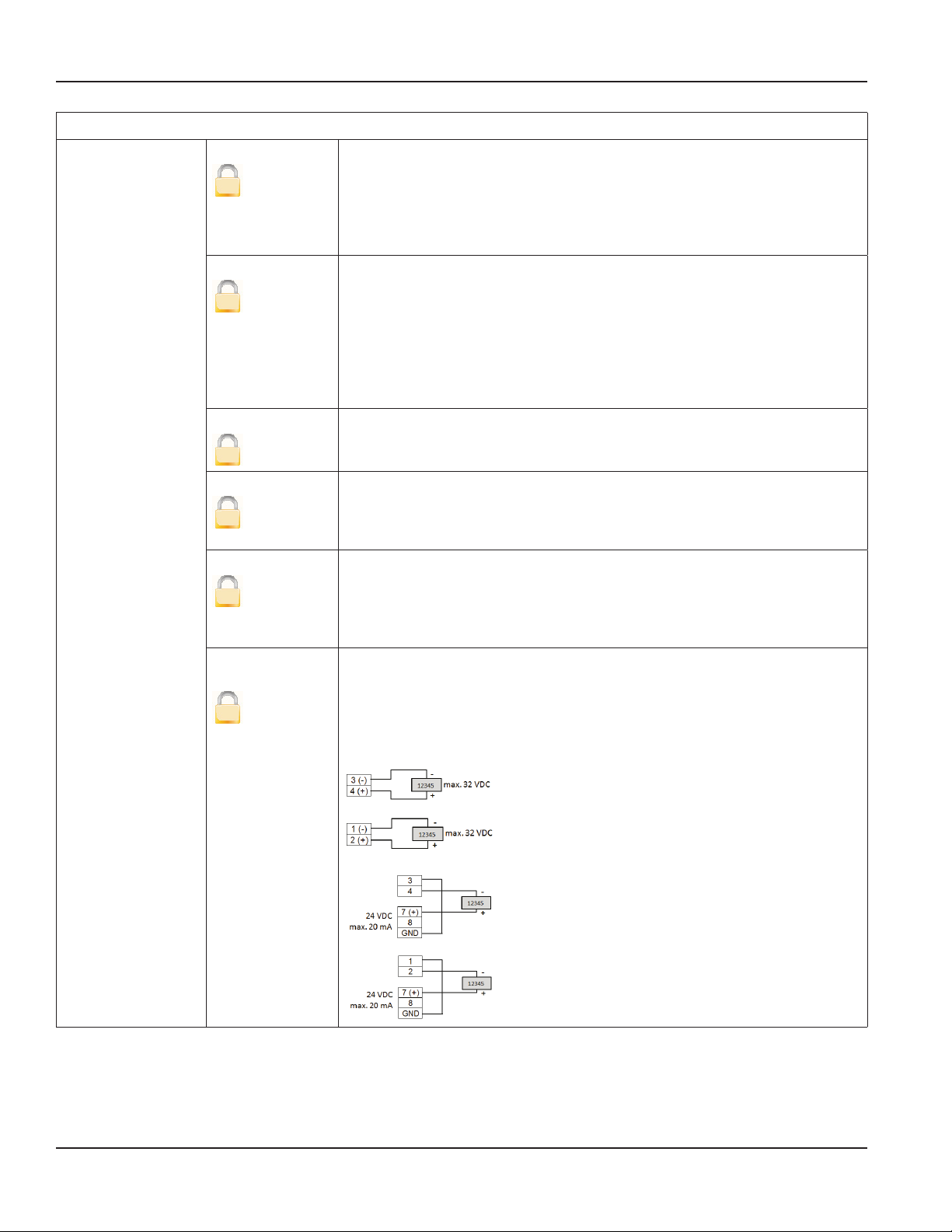
Input/Output Description Terminal
Analog Output 0…20 mA
4…20 mA
0…10 mA
RL < 800 Ohm 7 (+)
8 (–)
9 (GND)
Digital Output
1 Open collector max. 10 kHz
• Passive max. 32V DC, <100 Hz 100 mA, >100 Hz 20 mA
• Active 24V DC, 20 mA (can be powered by analog output if not
3 (–)
4 (+)
used)
2 Open collector max. 10 kHz
• Passive max. 32V DC, <100 Hz 100 mA, >100 Hz 20 mA
• Active 24V DC, 20 mA (can be powered by analog output if not
1 (–)
2 (+)
used)
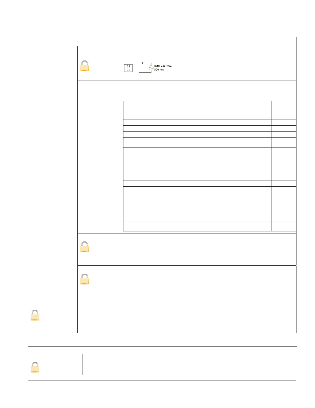
Solid-state relays max. 230V AC, 500 mA, max 1 Hz
(Function is linked with Output 2)
S1 and S2
Digital Input 5…30V DC 5 (–) and 6 (+)
RS-Interfaces RS-232, RS-485 and RS-422 with Modbus RTU.
Mode can be configured by DIP switches when termination is ON
or OFF.
Connector
Label
A A RxD —
B B — —
Z Z TxD B
Y Y — A
G G (GND)
RS Interfaces
422 232 485
USB USB Device CDC (Host Mass Storage) Micro USB
Ethernet Ethernet interface connection RJ45 socket
Page 18 January 2018MAG-UM-00379-EN-04
Page 19
Meter Setup
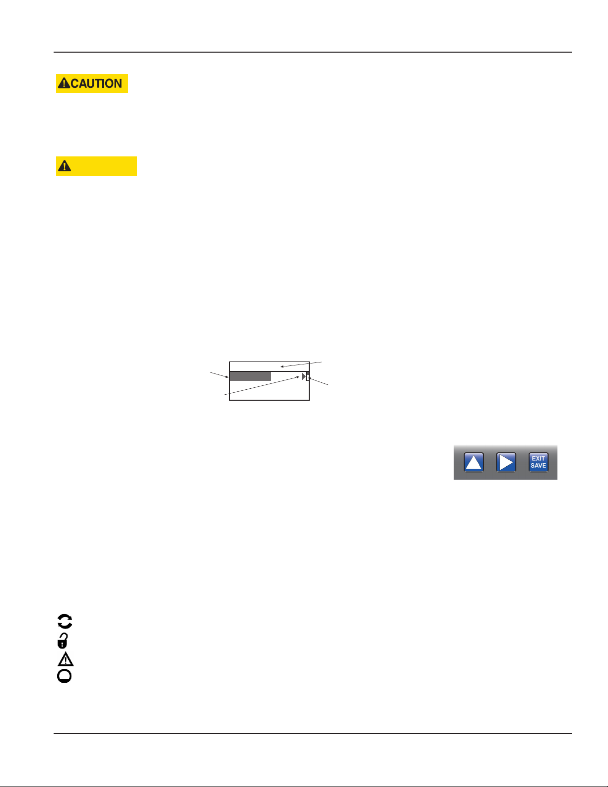
Main Menu
Scrollbar
M1000 Main Menu Programming Options
USE SEPARATE CABLE INLETS FOR CABLES CONNECTED TO THE SOLIDSTATE RELAY OUTPUT AND CABLES CONNECTED
TO THE OTHER INPUT/OUTPUTS.
IN MULTIPHASE NETS, SOLIDSTATE RELAY SHOULD HANDLE ONLY THE SAME PHASE THAT IS USED FOR POWERING
THEMETER.
ATTENTION
UTILISEZ DES ENTRÉES DE CÂBLE DISTINCTES POUR LES CÂBLES BRANCHÉS À LA SORTIE DES RELAIS STATIQUES ET
AUX CÂBLES BRANCHÉS AUX AUTRES ENTRÉES OU SORTIES.
POUR LES FILETS MULTIPHASES, LE RELAIS STATIQUE NE DEVRAIT SERVIR QUE LA MÊME PHASE UTILISÉE POUR
ALIMENTER LE COMPTEUR
M1000 MAIN MENU PROGRAMMING OPTIONS
Screen Layout
The following M1000 programming options are available from the Main Menu:
• Meter Setup
• Measurement
• Input/Outputs
• Totals
• Communications
• Miscellaneous
• Information
• Pin
Submenu
Indicates a submenu
Figure 24: Screen layout
Menu header
Function Buttons
All M1000 programming is accomplished using the three function buttons located on the front
of the amplifier. Screen navigation, digit, and parameter selection is performed by pressing a
combination of these three buttons.
Press to scroll through the menu screens or move downward in a list.
Press or EXIT SAVE button to enter a menu or move to the next submenu. The scrollbar on the upper right shows your
position in the list. Press EXIT SAVE to go back from a submenu to the upper menu.
To select parameters or values from a list in a menu point, first press until the parameter or value is displayed then press
EXIT SAVE to select it. The current number in the list is marked by a little black square to the left of the number . For example,
DN 50.
To change a parameter, press to enter the menu. The first character flashes. Press to change the value. Once you have
changed the value, press to move to the next value. Press EXIT SAVE to confirm the new value.
Status Icons
Communication interface is activated
Meter is unlocked
Error message
Empty pipe detection
Page 19 January 2018 MAG-UM-00379-EN-04
Page 20

M1000 Main Menu Programming Options
Setting Personal Identication Numbers (PINs)
The M1000 offers three levels of access to the individual menus: Administrative, Service and User level.
The applicable security level for each menu option is indicated as follows:
A
Administrative Service User
The M1000 security feature allows the option to restrict access to the meter by way of a 6-digit Personal Identification Number
(PIN). No PINs are set at the factory. The system administrator can set up a single PIN for each of the three different levels
of access:
• Administration – allows access to all M1000 menu configuration screens.
• Service – allows access to service-level and user-level menu configuration screens.
• User – allows access only to user-level menu configuration screens.
1. To activate password protection, navigate to the PIN menu. Set Control to ON.
2. Enter Login with the password 000000.
3. Return to the PIN menu and enter [User], [Service] and [Admin] password.
Once the password protection has been activated, enter your PIN under Login.
OTE:N The Login screen is available only after Control has been set to ON.
The lock open symbol appears.
The PIN grants you access to either Administrator, Service or User level with the respective access rights (marked with A, S and
U in this manual). You can now move to the menu and enter your parameters.
Without a login, you can read all parameters, but cannot change them.
Logging In
To change any parameter in the mag meter, the PIN entered must provide the proper security privilege required by
the parameter.
To enter a PIN, go to the Login menu and enter the PIN for the required security level.
Once you are properly logged in, the unlocked icon appears on the meter display.
S
U
OTE:N A PIN Error message displays if the incorrect PIN is entered.
Logging Out
To log out, enter an unknown PIN, then press EXIT SAVE.
Page 20 January 2018MAG-UM-00379-EN-04
Page 21

Menu Hierarchy Structure
Main_Menu → Meter Setup → Calibration
Scale Factor
Power Line Frequency
Excitation Freq
Empty Pipe Detect
Measurements → Flow Unit
Totalizer Unit
Full Scale Flow
Low Flow Cutoff
Flow Direction
Filter
Input/Outputs → Analog Output
Digital Input
Digital Outputs
Simulation
Totals → Clear T2
Communications → Interface
Modbus
M-Bus
HART
Ethernet
ADE
Miscellaneous → Log
Power Up
Settling Time
Language
Date
Time
EEPROM
Polar Voltage
Display Rotation
Contrast
Datalog Period
Info → Serial Number
Version
Compilation Date
OtpCrc
AppCrc
PIN → Control
User
Service
Admin
M1000 Main Menu Programming Options
Page 21 January 2018 MAG-UM-00379-EN-04
Page 22

M1000 Main Menu Programming Options
Meter Setup Menu
Meter Setup
Calibration Diameter
This parameter is set at the factory. In the event the amplifier is replaced,
verify that the pipe diameter matches the installed pipe size.
A
Detector Factor
A
Detector Zero
A
Amplifier Factor This parameter is set at the factory and is Read Only. This electronic
Coil Current This parameter (coil current to the detector) is set at the factory and is
Scale Factor
S
Power Line FrequencySFor optimum operation of the meter, set Power Line Frequency to 50 Hz or 60 Hz in this menu at
Changing the scale factor lets you adjust the meter’s accuracy without disturbing parameters set
by the factory. You can tune the meter to meet changing application requirements in a range of
±5% (0.95 to 1.05).
operating location.
This parameter is set at the factory. This factor compensates for accuracy
error as a result of the installed detector.
In the event the amplifier is replaced, this parameter must be
reprogrammed with the original detector zero.
This parameter is set at the factory. This parameter compensates for
accuracy error as a result of the installed detector.
If accuracy adjustment of the meter is required, refer to the scale factor.
calibration factor compensates for accuracy error as a result of the
installed amplifier.
Read Only. This factor compensates for accuracy error as a result of the
installed amplifier.
Excitation FrequencyAThis parameter is set at the factory. This value shows in which frequency the meter’s coils are
operated. Supported frequencies are dependent on the configured power line frequency and
meter’s size.
50 Hz 60 Hz
3.125 Hz 3.75 Hz
6.25 Hz 7.5 Hz
12.5 Hz 15 Hz
OTE:N When selecting excitation frequency, make sure to always observe that the ratio in
respect of power frequency is integer.
Empty Pipe DetectionSON/OFF
S
Threshold
S
Measured Measures the real empty pipe value. This parameter is Read Only.
When set to ON, an Empty Pipe condition indicates to the outputs
that the meter is not completely filled. When set to OFF, empty pipe
conditions are not detected.
Threshold value for empty pipe detection.
For liquids with lower conductivity or long cables the threshold value
must be increased. The actual value can be monitored in the next menu
“measured”.
Page 22 January 2018MAG-UM-00379-EN-04
Page 23

Measurement Menu
M1000 Main Menu Programming Options
Measurement
Flow Unit
U
Totalizer Unit
U
Full Scale Flow
S
Flow Units let you select among the Flow Units listed below. Flow units are automatically converted
into the selected unit.
Display Flow Unit Display Flow Unit
L/s Liters/Second gal/s Gallons/Second
L/min Liters/Minute gal/min Gallons/Minute
L/h Liters/Hour gal/h Gallons/Hour
m3/s Cubic Meters/Second MG/d MillionGallons/Day
m3/min Cubic Meters/Minute IG/s ImperialGallons/Second
m3/h Cubic Meters/Hour IG/min ImperialGallons/Minute
ft3/s Cubic Feet/Second IG/h ImperialGallons/Hour
ft3/m Cubic Feet/Minute oz/min Ounce/Minute
ft3/h Cubic Feet/Hour bbl/min Barrel/Minute
This parameter establishes the units of measure for the totalizers.
Display Totalizer Unit Display Totalizer Unit
L Liters MG Million Gallons
hL Hectoliter IG Imperial Gallons
3
m
3
ft
gal U.S. Gallons ac/ft Acre per foot
This parameter sets the maximum flow the system is expected to measure. This parameter has
influence on other system parameters like analog output or low flow cutoff.
In terms of flow velocity, the meter’s range is 0.3…12 m/sec.
The full scale flow is valid for both flow directions.
Cubic Meters bbl Barrel
Cubic Feet oz Fluid Ounces
Low Flow Cutoff
U
Flow Direction
S
OTE:N Note: If the flow rate exceeds the full scale setting, an error message indicates that the
configured full scale range has been exceeded.
Low Flow Cutoff defines the threshold at which flow measurement will be forced to zero. The cutoff
value can be from 0% to 10% of the full scale flow. Increasing this threshold will help prevent false
readings during “no flow” conditions possibly caused by vibrations or liquid fluctuations.
Flow direction lets you set the meter to measure forward flow only (unidirectional) or both forward and
reverse flow (bidirectional).
Unidirectional means that the flow is totalized in only one direction. The flow direction is indicated by
the arrow printed on the detector label. In this mode, the two totalizers T1+ and T2+ can be used as
totalizers and resettable day counter.
Bidirectional means the flow is totalized in both directions. The totalizer T1+ and T2+ registers forward
flow and the totalizer T1– and T2– in reverse flow direction. The net totalizer T1N and T2N shows the
difference between T+ and T–.
A change of the flow direction can be signalized by the digital outputs.
Page 23 January 2018 MAG-UM-00379-EN-04
Page 24

M1000 Main Menu Programming Options
Measurement
Filter
S
Median
S
Moving Average
S
Display
S
The Median Filter (MDN) reduces noise on the measuring signal. The filter
level can be adjusted from 7 up to 13 or switched off.
Moving average filter (MAV) smooths out short-term fluctuations. The value
can be adjusted from 1 to 200 measuring periods.
The delay is calculated:
Delay [s] = ( MAV – 1) x T
The time (T) is given by the adjusted excitation frequency of the meter.
Excitation frequency [Hz] T = Time for filter delay (s)
15 0.03333
12.5 0.040
7.5 0.06666
6.25 0.080
3.75 0.13333
3.125 0.160
For example: MAV = 20 and the excitation frequency is 6.25 Hz
means T=0.08 s, the delay is 1.52 s.
Moving average filter smooths out short-term fluctuations only for the
display. The value can be adjusted from 1 to 200 measuring periods.
For calculation of the delay see Moving Average above.
Page 24 January 2018MAG-UM-00379-EN-04
Page 25

Input/Outputs Menu
Analog Output Range
S
Alarm Mode
S
M1000 Main Menu Programming Options
Input/Outputs
This parameter establishes the range of the analog output signal: 0…100% (= full
scale). The following current ranges are available to you:
Current Output
0…20 mA
4…20 mA
0…10 mA
Analog output active
Analog output passive
OTE:N When an error message is displayed, the current is set according the
programing of the Alarm Mode below.
When you select bidirectional operation, you can signal flow direction via
digital outputs.
This parameter configures the behavior of the analog output during alarm
conditions. Three options exist for this parameter: OFF, LOW and HIGH.
OFF: Analog signal is based on flow rate and always within the configured range.
LOW: During alarm conditions, the analog signal will be 2 mA less than the
configured lower range. (only on 4…20 mA range).
HIGH: During alarm conditions, the analog signal will be 2 mA more than the
configured upper range.
For example, if the analog range is 4…20 mA and the alarm mode is set to HIGH,
then during a full scale flow alarm condition, the analog output current will be
22 mA.
Digital Input
S
Digital input lets you reset totalizers (Remote reset), or interrupt flow measurement (PosZeroReturn).
• Remote Reset – Clears totalizer T2 (unidirectional)
• Pos Zero Return – Forces flow rate to zero (does not totalize)
Input switching is provided by applying an external potential of 5…30V DC
or by an internal voltage source of 24V DC (Analog output if not used).
Page 25 January 2018 MAG-UM-00379-EN-04
Page 26
M1000 Main Menu Programming Options
Inputs/Outputs
Digital Outputs
(continued on next
page)
Pulse Width
S
Pulse/Unit
S
Frequency
S
Set Min./Max.
S
Preset Amount
S
Out 1 Function
Out 2 Function
S
(continued on next
page)
This parameter establishes the “On” duration of the transmitted pulse. The
configurable range is 0…2000 ms. If 0 ms is configured, pulse width is
automatically adapted depending on pulse frequency (pulse/pause ratio 1:1).
During the configuration the program checks if pulses/unit and pulse width are
in accordance with full scale defined, if not an error alarm is displayed. In case of
an error alarm, scale, pulse width or full scale need to be adapted.
The Pulses/Unit parameter lets you set how many pulses per unit of measure
will be transmitted. The maximum output frequency of 10,000 pulses/sec.
(10 kHZ) must not be exceeded.
For example, assuming the unit of measure is gallons:
• Setting the Pulses/Unit to 1 will transmit 1 pulse every gallon
• Setting the Pulses/Unit to 0.01 will transmit 1 pulse every 100 gallons
You must configure pulses/unit if the function of the selected output is to be
forward, reverse or AMR pulse.
This parameter establishes to define the digital output as frequency output. The
full scale frequency configurable range is 0.01…10,000 Hz.
The Flow Set Point (min, max) establishes as a percentage of full scale flow,
the threshold at which the output alarm will be activated. You can freely select
thresholds in 1% steps. Flow rates below/above the threshold will activate the
output alarm.
Preset amount lets you set the reset value for the associated PS totalizer when
the digital input is set to Batch Reset. You can configure preset amount in the
adjusted volume unit.
Preset amount is counted down from the configured value to 0 and a digital
output shows that the preset amount has been reached.
From the sub-menus Out 1 Function and Out 2 Function, you can configure
functional operation of the 2 digital outputs. For example, you can select
“forward pulse” for the digital output and define the pulses-per-totalizer unit via
“pulse scale”.
The two outputs can be operated as open collector passively or actively.
Passive output:
Active output (if analog output is not used):
Page 26 January 2018MAG-UM-00379-EN-04
Page 27
Inputs/Outputs
M1000 Main Menu Programming Options
Digital Outputs
(continued)
Out 1 Function
Out 2 Function
S
(continued)
Out Type 1
S
Out Type 2
S
Solid-State Relay
The solid-state relay is functionally linked with Output 2. See the table below.
The following functions can be selected for the Outputs 1 to 2 as well as for
the solid-state relay. The solid-state relay function is linked with the function of
Output 2.
Out2 /
Function Meaning Out1
Off Digital output is switched off. X X
Test Used only for the Verification Device. X X
Comparator TBD X X
Empty Pipe
Error
Error Alarm Indicates a meter error condition. X X
Forward
Pulses
Reverse Pulses
Direction Indicates current flow direction. X X
Loopback Shows the status of the digital input. X X
Min./Max.
Alarm
Frequency TBD X X
Rotary
Encoder
Preset
This parameter lets you set the output switch to normally open or normally
closed. If normally open is selected, the output switch is open (no current) when
the output is inactive, and closed (current flows) when the output is active.
If normally closed is selected, the output switch is closed (current flows) when
the output is inactive, and open (no current) when the output is active.
Indicates when a pipe is empty. X X
Generates pulses during forward flow
conditions.
Generates pulses during reverse flow
conditions.
Establishes, as a percentage of full scale flow,
the threshold at which the output alarm will
be activated. Flow rates below or above the
threshold will activate the output alarm.
TBD X X
Indicates when a preset batch amount has
been realized.
Solid-
State
Relay
X X
X X
X X
X X
Simulation
S
Totals Menu
Clear T2
U
Flow Simulation provides analog and digital output simulation based on a percentage of the full
scale flow in cases where no real flow is occurring. The range of simulation is –100…100% in steps
of 10% of the full scale flow. This function still remains active once you have left the menu. It is
necessary to set it to OFF to deactivate it. If the simulation is still active, the letter “S” will be displayed
in the measuring mode.
Totals
The unidirectional Totalizer T2 is reset within the menu manager.
Page 27 January 2018 MAG-UM-00379-EN-04
Page 28

M1000 Main Menu Programming Options
Communication Menu
Communication: Port Settings
Interfaces Modbus RTU RS-232, RS-485 and RS-422 with Modbus RTU.
Connector
Label
A A RxD —
B B — —
Z Z TxD B
Y Y — A
G G (GND)
Mode can be configured by DIP switches also if Termination is ON or OFF.
RS Interfaces
422 232 485
See Figure 23 on page 18 for wiring
diagram.
M-Bus For future release.
HART For future release.
Modbus Address This parameter configures the Modbus address in the range from 1…247.
RS-232,
RS-422,
Baudrate: 1200, 2400, 4800, 9600, 19200, 38400 Bd
Parity: Even, Odd, Mark
RS-485
M-Bus Address For future release.
Ethernet IP Address For future release.
IP Mask
IP Gateway
MAC Address
ADE Control On or Off
Protocol 1 standard messages
2 extended messages
Dial 4 to 9
Resolution 0.001 / 0.01 / 0.1 / 1 / 10 / 100 / 1000 / 10,000
Page 28 January 2018MAG-UM-00379-EN-04
Page 29
M1000 Main Menu Programming Options
Miscellaneous Menu
Miscellaneous
Log Off, On and Preset
Power Up The number of times that the unit has been powered on.
Settling Time Measures settling of coils and must be less than one quarter of the excitation period. Zero ms if no
detector is connected.
Language This parameter allows changing the current language. English is the default setting.
The following languages are supported:
German (Deutsch), Czech (Cestina), Spanish (Espanol), French (Francais), Russian (России),
Italian (Italiano).
Date Set date of the system in the format day, month, year [DD.MM.YY] used for data logging.
Time Set time of the system in the format hour, minutes, seconds [HH.MM.SS] used for data logging.
EEPROM Delete all data logging information from the EEPROM.
Polar Voltage Measure electrode polarizing voltage in ± V (only for service purpose).
Display Rotation The Display can be rotated to 0°, 90°, 180° and 270°.
Contrast The contrast of the display can be adjusted between 14 (low) and 49 (high).
Datalog Period The data logging period can be adjusted to the following increments:
• Every 15 min / 1 h / 6 h / 12 h / 24 h
There is a 500 kB memory with about 30,000 data records for data logging available. The logging
capacity is as following (Unidirectional mode):
Time Period Duration
15 min up to 312 days
1 h up to 1250 days
6 h up to 20 years
12 h up to 40 years
24 h up to 80 years
Startup, configuration, and error events that are logged can reduce the data logging capacity. Logging
in bidirectional mode reduces the logging capacity by about 40%.
The logging information can be downloaded by a PC program, which can be ordered with the
following part number: 67354-010.
Information Menu
Serial Number Serial number of the electronic board.
Version Software version of the device.
Compilation Date Date of the software version.
OPT CRC Checksum of the software update.
APP CRC Checksum of the application.
Info
Page 29 January 2018 MAG-UM-00379-EN-04
Page 30
Maintenance
PIN Menu
PIN
Control
Activate and deactivate the PIN.
A
User
Users logged in with this PIN have access to all user levels. Users at this level do not have access to
Service or Admin functions.
U
Service
Users logged in with this PIN have access to both service and user-level procedures. Users at this level
do not have access to Admin functions.
S
Admin
Users logged in with this PIN have access to all procedures. Users at this level have full access to the
meter.
A
Login Screen
Login
Login This screen is available only after the password protection (PIN Control) has been set to ON. Enter your
6-digit password.
MAINTENANCE
Mandatory, routine or scheduled maintenance should not be required for the M1000 Mag Meter electronics or flow tube after
proper installation. However, some occurrences may require personnel to perform the following:
• Flow tube and electrode cleaning
• Circuit board replacement
DO NOT CLEAN COMPONENTS INSIDE THE AMPLIFIER OR JUNCTION BOX.
AVERTISSEMENT
NE NETTOYEZ PAS LES COMPOSANTES À L'INTÉRIEUR DE L'AMPLIFICATEUR OU DE LA BOÎTE DE JONCTION.
Cleaning the Flow Tube and Electrode
At times flow tube, electrodes, amplifier/junction box housings and the amplifier window may need periodic cleaning,
depending on process fluid properties, fluid flow rate and surrounding environment.
Clean the flow tube and electrodes by following the material handling and cleaning procedures documented in Material
Safety Data Sheet (MSDS) guidelines for the products(s) that were in contact with the flow tube and electrodes.
Should flow tube and/or electrode cleaning become necessary:
1. Disconnect detector from pipeline.
2. Clean electrodes according to MSDS guidelines.
3. Reconnect detector to pipeline.
Page 30 January 2018MAG-UM-00379-EN-04
Page 31

Troubleshooting
TROUBLESHOOTING
The M1000 mag meter is designed for many years of optimal performance. However, should it malfunction, there are certain
things that we recommend you check before contacting our Technical Support department or your local Badger Meter
Representative.
Errors & Warnings
OTE:N The M1000 display flashes whenever an error is detected.
Description Possible Cause Recommended Action
Coil disconnected • Meter not connected.
• Connection to meter interrupted.
Coil shorted Coil cables shorted. Check coil cables .
Empty pipe Pipe may not be full. Make sure that pipe is always filled at the
Medium with low conductivity. Eventually calibrate new, see calibration of fluid
Cable broken or disconnected. Check the cable for the empty pipe signal.
Range Actual flow rate is exceeding the programmed full
scale by more than 100%
Pulse output Pulse rate exceed the maximum Reduce pulse scale (pulse/unit) and/or reduce
AD error Input signal from detector too high. Check the grounding scheme of the meter
Excitation
frequency
EEPROM Configuration file is missing. Contact Badger Meter Technical Support.
Configuration Configuration file is corrupted. Contact Badger Meter Technical Support.
Measure Timeout Measurement was not completed within specific
Some frequently occurring situations:
The excitation frequency is too high for this
detector.
time.
Check if meter is connected and make sure that
cable connection is not interrupted or contact
Badger Meter Technical Support.
measuring point.
monitoring.
Reduce flow rate or increase the programmed full
scale.
pulse width configuration.
installation. See "Meter Grounding" on page 14.
Decrease the excitation frequency in the Meter
Setup.
Contact Badger Meter Technical Support.
Description Possible Cause Recommended Action
Meter does not
function
Fluid is flowing,
however display
shows zero
Inaccurate
measurement
No auxiliary power. Apply auxiliary power.
Fuse is defective. Replace fuse.
Signal cable is not connected or connection is
interrupted.
Detector installed opposite to forward flow
direction (see arrow on type plate).
Connection cable for coils or electrodes mixed-up. Check connection cable.
Wrong parameters. Check parameters (detector, amplifier and size) per
Pipe not completely full. Check if the measuring pipe is completely full.
Check signal cable.
Turn detector by 180°.
"Specifications" on page 33.
Page 31 January 2018 MAG-UM-00379-EN-04
Page 32

LED1
LED2
LED3
LED10
Main Board
LED7
LED6
LED8
LED13
LED5
Display Board
Troubleshooting
LED Status Indicators
When the LEDs on the circuit board are active, they indicate the status of the device.
LED Device Status Label on PCB
LED1 Coil loop connected COIL
LED2 Communication – receiving RX
LED3 Communication – transmitting TX
LED5 Flash memory activity DISK
LED6 Digital output #1 OUT 1
LED7 Digital output #2 OUT 2
LED8 Digital input INPUT
LED10 Power ON POWER
LED13 USB, HOST mode USB
Page 32 January 2018MAG-UM-00379-EN-04
Page 33

Connecting an ORION ADE Endpoint to the M1000 Meter
CONNECTING AN ORION ADE ENDPOINT TO THE M1000 METER
OTE:N Connect the endpoint as described. The endpoint automatically updates within one hour. You can force an update
using the Endpoint Utility. See the endpoint user manual for programming information.
Wiring
To connect the ADE endpoint, connect:
ADE Wire M1000 Terminal
Red (Power/Clock) Input +
Green (Data) Out 1 +
Black (Ground) Out 1 –
Connect a jumper wire from Out 1 negative (–) to INPUT negative (–).
black ADE_GROUND
green ADE_DATA
+IN- +OUT1- +OUT2-
red ADE_CLOCK
Programming
Changing the following settings automatically configures Input and Output 1 for ADE.
To program the M1000 meter for the endpoint to Output #1 (forward flow):
1. Navigate to COMMUNICATION > ADE > CONTROL.
2. Use the arrows to change the values, then press EXIT/SAVE.
3. Repeat steps 1 and 2 for Control, Protocol, Dials and Resolution (the Resolution range is 0.0001…10,000).
4. Press EXIT/SAVE.
Page 33 January 2018 MAG-UM-00379-EN-04
Page 34

Specications
SPECIFICATIONS
Flow Range 0.03…12 m/s
Accuracy ± 0.3% of reading, ± 2 mm/s
Conductivity Min. 5 µS/cm (20 µS/cm for demineralized water)
Fluid Temperature With Remote Amplifier:
PTFE 302° F (150° C),
Hard rubber 178° F (80° C)
Ambient Temperature –4…140° F (–20…60° C)
Flow Direction Uni-directional or bi-directional
Analog Output 0/4…20 mA / 0…10 mA, flow direction is displayed on a separate status output
Pulse Output 2 open collectors, passive 32V DC, 0…100 Hz 100 mA, 100…10,000 Hz 20 mA, optional
active
Frequency Output Max. 10 kHz (open collector)
Communication RS232, RS422, RS485 Modbus RTU
Empty Pipe Detection Field-tunable for optimum performance based on specific application
Min-Max Flow Alarm Programmable outputs 1…100% of flow
Low Flow Cutoff Programmable 0…10% of maximum flow
Galvanic Separation Functional 500 volts
Pulse Width Programmable 5…2000 ms
Coil Power Pulsed DC
Repeatability 0.1%
Display Two lines x 15 characters (7 on top + 8 on bottom), LCD display
Programming 3 external buttons
Units of Measure Gallons, ounces, MGD, liters, cubic meters, cubic feet, imperial gallon, barrel, hectoliter and
acre feet
Power Supply 92…275V AC (50 / 60 Hz), <13 VA optional 9…36V DC, 4W
Amplifier Housing Powder-coated aluminium die cast
Detector Housing Carbon steel
Linear Materials Hard Rubber, PFA, PTFE
Electrodes Materials Standard: Hastelloy C
Grounding Rings Stainless steel
Mounting Detector-mount or remote wall mount
Approvals NSF Listed: Models with hard rubber liner 4" size and up; PTFE liner, all sizes
Cable Insertion 2 x M 20
Process Connection Flange: DIN, ANSI, JIS, AWWA
Nominal Pressure Up to 232 psi (16 bar)
Protection Class Standard: NEMA 4X (IP67); Optional: NEMA 6P
Pollution Degree 2
Installation Category II
Altitude 2500 m
Humidity 90% R.H. max.
Electrical Supply 100…240V AC (±10%). 50/60 Hz, 15 Watts
NOTE: Mains supply voltage fluctuations are not to exceed ±10% of the nominal voltage
supply.
With Meter-Mounted Amplifier:
PTFE 212° F (100° C),
Hard rubber 178° F (80° C)
Page 34 January 2018MAG-UM-00379-EN-04
Page 35

INTENTIONAL BLANK PAGE
User Manual
Page 35 January 2018 MAG-UM-00379-EN-04
Page 36

M-Series® M1000, Electromagnetic Flow Meter
Control. Manage. Optimize.
M-SERIES is registered trademark of Badger Meter, Inc. Other trademarks appearing in this document are the property of their respective entities. Due to continuous research,
product improvements and enhancements, Badger Meter reserves the right to change product or system specications without notice, except to the extent an outstanding
contractual obligation exists. © 2018 Badger Meter, Inc. All rights reserved.
www.badgermeter.com
The Americas | Badger Meter | 4545 West Brown Deer Rd | PO Box 245036 | Milwaukee, WI 53224-9536 | 800-876-3837 | 414-355-0400
México | Badger Meter de las Americas, S.A. de C.V. | Pedro Luis Ogazón N°32 | Esq. Angelina N°24 | Colonia Guadalupe Inn | CP 01050 | México, DF | México | +52-55-5662-0882
Europe, Eastern Europe Branch Oce (for Poland, Latvia, Lithuania, Estonia, Ukraine, Belarus) | Badger Meter Europe | ul. Korfantego 6 | 44-193 Knurów | Poland | +48-32-236-8787
Europe, Middle East and Africa | Badger Meter Europa GmbH | Nurtinger Str 76 | 72639 Neuen | Germany | +49-7025-9208-0
Europe, Middle East Branch Oce | Badger Meter Europe | PO Box 341442 | Dubai Silicon Oasis, Head Quarter Building, Wing C, Oce #C209 | Dubai / UAE | +971-4-371 2503
Slovakia | Badger Meter Slovakia s.r.o. | Racianska 109/B | 831 02 Bratislava, Slovakia | +421-2-44 63 83 01
Asia Pacic | Badger Meter | 80 Marine Parade Rd | 21-06 Parkway Parade | Singapore 449269 | +65-63464836
China | Badger Meter | 7-1202 | 99 Hangzhong Road | Minhang District | Shanghai | China 201101 | +86-21-5763 5412
Switzerland | Badger Meter Swiss AG | Mittelholzerstrasse 8 | 3006 Bern | Switzerland | +41-31-932 01 11
 Loading...