

Badger Meter ILR 730, ILR 700, ILR 710, ILR 720 User Manual
Industrial Oval Gear
Meters and Registers
IOG-UM-00046-EN-09 (February 2015)
User Manual

Industrial Oval Gear, Meters and Registers
Page ii February 2015IOG-UM-00046-EN-09

User Manual
CONTENTS
Scope of this Manual . . . . . . . . . . . . . . . . . . . . . . . . . . . . . . . . . . . . . . . . . . . . . . . . . . . . . . . . . . . . . . . . . . . 5
Product Unpacking and Inspection . . . . . . . . . . . . . . . . . . . . . . . . . . . . . . . . . . . . . . . . . . . . . . . . . . . . . . . . . . 5
Product Identication. . . . . . . . . . . . . . . . . . . . . . . . . . . . . . . . . . . . . . . . . . . . . . . . . . . . . . . . . . . . . . . . . . . 5
Disclaimer . . . . . . . . . . . . . . . . . . . . . . . . . . . . . . . . . . . . . . . . . . . . . . . . . . . . . . . . . . . . . . . . . . . . . . . . . . 5
Questions or Service Assistance . . . . . . . . . . . . . . . . . . . . . . . . . . . . . . . . . . . . . . . . . . . . . . . . . . . . . . . . . . . . 5
Safety . . . . . . . . . . . . . . . . . . . . . . . . . . . . . . . . . . . . . . . . . . . . . . . . . . . . . . . . . . . . . . . . . . . . . . . . . . . . . 6
Explosion and Fire Hazards . . . . . . . . . . . . . . . . . . . . . . . . . . . . . . . . . . . . . . . . . . . . . . . . . . . . . . . . . . . . 6
Meter Hazards . . . . . . . . . . . . . . . . . . . . . . . . . . . . . . . . . . . . . . . . . . . . . . . . . . . . . . . . . . . . . . . . . . . . 6
Meter Installation . . . . . . . . . . . . . . . . . . . . . . . . . . . . . . . . . . . . . . . . . . . . . . . . . . . . . . . . . . . . . . . . . . . . . 7
Meter Operation . . . . . . . . . . . . . . . . . . . . . . . . . . . . . . . . . . . . . . . . . . . . . . . . . . . . . . . . . . . . . . . . . . . . . . 7
Pressure Drop vs Flow Rate . . . . . . . . . . . . . . . . . . . . . . . . . . . . . . . . . . . . . . . . . . . . . . . . . . . . . . . . . . . . 8
Register Operation . . . . . . . . . . . . . . . . . . . . . . . . . . . . . . . . . . . . . . . . . . . . . . . . . . . . . . . . . . . . . . . . . . . 10
Normal Operation . . . . . . . . . . . . . . . . . . . . . . . . . . . . . . . . . . . . . . . . . . . . . . . . . . . . . . . . . . . . . . . . . 10
Status . . . . . . . . . . . . . . . . . . . . . . . . . . . . . . . . . . . . . . . . . . . . . . . . . . . . . . . . . . . . . . . . . . . . . . . . . 10
Totalizers . . . . . . . . . . . . . . . . . . . . . . . . . . . . . . . . . . . . . . . . . . . . . . . . . . . . . . . . . . . . . . . . . . . . . . . 10
Flow Rate. . . . . . . . . . . . . . . . . . . . . . . . . . . . . . . . . . . . . . . . . . . . . . . . . . . . . . . . . . . . . . . . . . . . . . . 10
Battery . . . . . . . . . . . . . . . . . . . . . . . . . . . . . . . . . . . . . . . . . . . . . . . . . . . . . . . . . . . . . . . . . . . . . . . . 10
Checksum . . . . . . . . . . . . . . . . . . . . . . . . . . . . . . . . . . . . . . . . . . . . . . . . . . . . . . . . . . . . . . . . . . . . . . 11
Display Scale Factor . . . . . . . . . . . . . . . . . . . . . . . . . . . . . . . . . . . . . . . . . . . . . . . . . . . . . . . . . . . . . . . . 11
Register Programming . . . . . . . . . . . . . . . . . . . . . . . . . . . . . . . . . . . . . . . . . . . . . . . . . . . . . . . . . . . . . . . . . 12
Changing the Unit of Measure . . . . . . . . . . . . . . . . . . . . . . . . . . . . . . . . . . . . . . . . . . . . . . . . . . . . . . . . . 12
Changing the Scale Factor . . . . . . . . . . . . . . . . . . . . . . . . . . . . . . . . . . . . . . . . . . . . . . . . . . . . . . . . . . . . 12
Changing the Meter Pulse Rate. . . . . . . . . . . . . . . . . . . . . . . . . . . . . . . . . . . . . . . . . . . . . . . . . . . . . . . . . 13
Changing the Register Orientation . . . . . . . . . . . . . . . . . . . . . . . . . . . . . . . . . . . . . . . . . . . . . . . . . . . . . . 13
Changing the Display Mode. . . . . . . . . . . . . . . . . . . . . . . . . . . . . . . . . . . . . . . . . . . . . . . . . . . . . . . . . . . 14
Exiting Programming Mode . . . . . . . . . . . . . . . . . . . . . . . . . . . . . . . . . . . . . . . . . . . . . . . . . . . . . . . . . . . 14
Additional Programming: Industrial Analog and Industrial Pulse (ILR 710 & ILR 730) . . . . . . . . . . . . . . . . . . . . . . . 15
Register Output Specications & Wiring . . . . . . . . . . . . . . . . . . . . . . . . . . . . . . . . . . . . . . . . . . . . . . . . . . . 18
Pulse Transmitter (Model ILR 740) . . . . . . . . . . . . . . . . . . . . . . . . . . . . . . . . . . . . . . . . . . . . . . . . . . . . . . . 21
Pulse Transmitter (Model ILR 741) . . . . . . . . . . . . . . . . . . . . . . . . . . . . . . . . . . . . . . . . . . . . . . . . . . . . . . . 22
Pulse Transmitter (for 1/4"). . . . . . . . . . . . . . . . . . . . . . . . . . . . . . . . . . . . . . . . . . . . . . . . . . . . . . . . . . . . 23
Hall Eect Switch. . . . . . . . . . . . . . . . . . . . . . . . . . . . . . . . . . . . . . . . . . . . . . . . . . . . . . . . . . . . . . . . . . 23
Reed Switch . . . . . . . . . . . . . . . . . . . . . . . . . . . . . . . . . . . . . . . . . . . . . . . . . . . . . . . . . . . . . . . . . . . . . 23
Pulses Per Liter . . . . . . . . . . . . . . . . . . . . . . . . . . . . . . . . . . . . . . . . . . . . . . . . . . . . . . . . . . . . . . . . . . . 23
Pulse Chart of Approximate Values . . . . . . . . . . . . . . . . . . . . . . . . . . . . . . . . . . . . . . . . . . . . . . . . . . . . . . . . . 24
Page iii February 2015 IOG-UM-00046-EN-09

Industrial Oval Gear, Meters and Registers
Page iv February 2015IOG-UM-00046-EN-09

Scope of this Manual
SCOPE OF THIS MANUAL
This manual contains installation and operation instructions for the Badger Meter Industrial Line of Oval Gear Meters
and Registers.
Proper performance and reliability of these meters and registers depends upon installation in accordance with
these instructions.
Be sure to read all safety information beginning on page 6 and throughout this manual.
PRODUCT UNPACKING AND INSPECTION
Upon receipt of the product, perform the following unpacking and inspection procedures:
OTE:N If there is damage to the shipping container, request the carrier to be present when unpacking the product.
Carefully open the shipping package and follow any instructions marked on the exterior. Remove all packing material and
carefully lift the product from the package.
Retain the package and all packing material for possible use in reshipment or storage.
Visually inspect the product and applicable accessories for any physical damage such as scratches, loose or broken parts or
any other sign of damage that may have occurred during shipment.
OTE:N If you find damage, request an inspection by the carrier’s agent within 48 hours of delivery and file a claim
with the carrier.
A claim for equipment damage in transit is the sole responsibility of the purchaser.
PRODUCT IDENTIFICATION
Record the product identification numbers from the nameplate.
Model #____________________________________________
Serial Number # ____________________________________
Tag # ______________________________________________(if applicable)
DISCLAIMER
The user/purchaser is expected to read and understand the information provided in this manual, follow any listed safety
precautions and instructions and keep this manual for future reference.
Misuse, mishandling and/or inadequate maintenance may impair performance and/or compromise safety.
QUESTIONS OR SERVICE ASSISTANCE
If you have questions regarding the product or this document contact:
Badger Meter, Inc.
P.O. Box 245036
Milwaukee, WI 53224-9536
Telephone: 414-355-0400, 800-876-3837
Fax: 888-371-5982
Web site: www.badgermeter.com
or call your local Badger Meter representative.
Page 5 February 2015 IOG-UM-00046-EN-09

Safety
SAFETY
Explosion and Fire Hazards
• Improper grounding, poor ventilation, open flames or sparks can cause a hazardous condition and result in an
explosion or fire and cause serious injury.
• Be sure the fluid system is properly grounded. See your pump instruction manual for details.
• If there is static sparking or if you feel an electric shock while using the meter, stop dispensing immediately. Identify
and correct the problem before continuing.
• Provide fresh air ventilation. This will avoid the buildup of fumes from the fluid being dispensed.
• Do not smoke while dispensing flammable fluids.
• Keep the dispensing area free of debris including solvents, rags and spilled gasoline.
Meter Hazards
• Equipment misuse can cause the meter to rupture or malfunction and cause serious injury.
• This equipment is for professional use only.
• Read all instructions, tags and labels before operating the equipment.
• Use the equipment only for its intended purpose.
• Do NOT modify or alter the equipment.
• Do NOT leave equipment unattended while dispensing.
• Check equipment daily. Repair or replace worn or damaged parts immediately.
• Do NOT exceed the maximum working pressure level of the lowest rated system component.
• Use only extensions and nozzles that are designed for use with this equipment.
• Use only fluids and solvents that are compatible with the equipment. Read all fluid and solvent
manufacturer’s warnings.
• Tighten all fluid connections before operating this equipment.
• Do NOT stop or deflect leaks with hands, body, gloves or rags.
• Do NOT dispense towards any person or any part of the body.
• Do NOT place hands or fingers over the end of or into the dispense valve.
• Comply with all local, state and federal fire, electrical and safety regulations.
• Use of this product in a manner other than specified in this manual may result in impaired operation or damage
to equipment.
These meters are designed to dispense a wide range of chemicals. Consult the factory for chemical compatibility.
Page 6 February 2015IOG-UM-00046-EN-09
Meter Installation
METER INSTALLATION
READ THE FOLLOWING INFORMATION AND HAVE A THOROUGH UNDERSTANDING BEFORE PROCEEDING WITH METER
INSTALLATION. ONLY QUALIFIED PERSONNEL SHOULD PERFORM METER INSTALLATION.
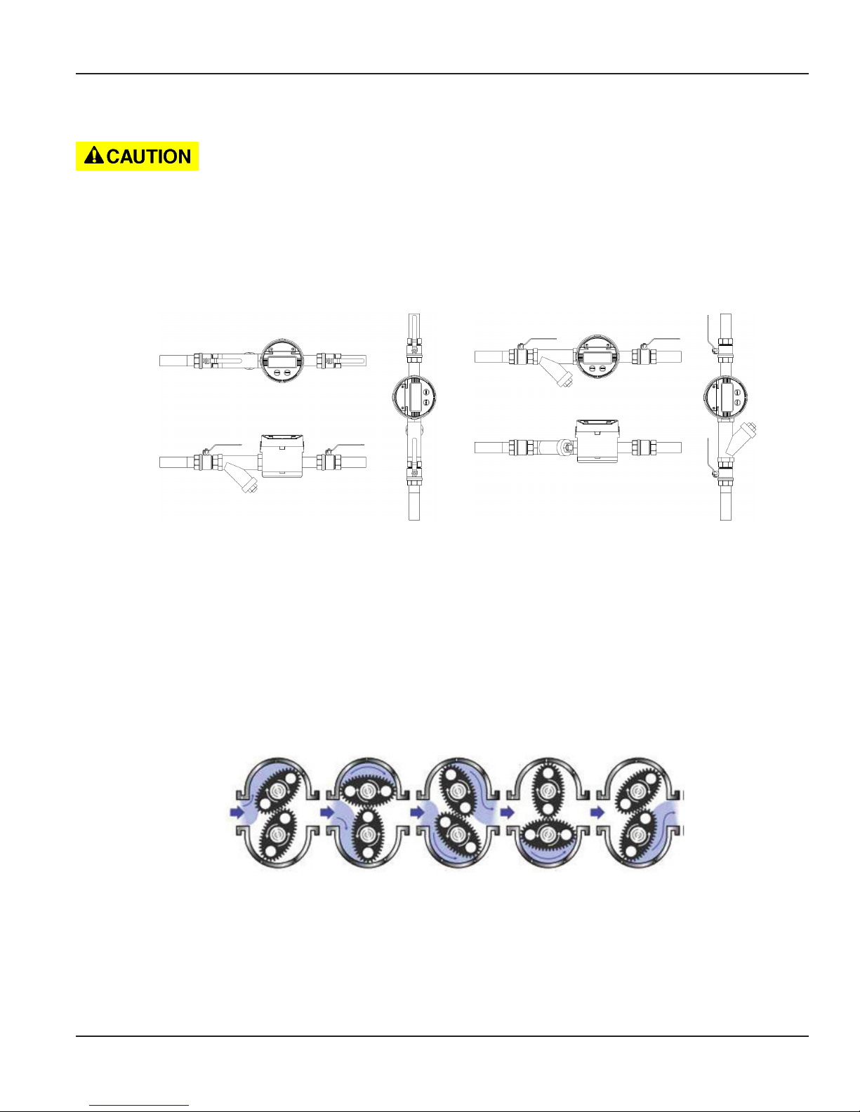
• Install a type 60 mesh strainer or Y or basket as close to the inlet side of the meter as possible. Strainers prevent dirt
and other fluid contaminants from impeding meter performance. Strainers require periodic cleaning, as clogged
strainers also impede meter performance. Contact your local representative for specific information, per your
specific application.
Strainer
Strainer
Figure 1: Meter installation
• Turn off any associated pumps to reduce line pressure and slowly fill the line and meter with fluid before restarting
pumps. Doing so reduces the possibility of meter damage caused by errant air pressures in the line and meter.
• Make sure all pipe conforms to the same pressure output rating as the pump.
• Make sure to apply thread sealant to all pipe threads.
• Check for and repair leaks upon initialization of fluid flow.
METER OPERATION
Figure 2: Operation depiction
Fluid enters the inlet port and then passes through the metering chamber. Inside the chamber, fluid forces the internal gears
to rotate before exiting through the outlet port. Each rotation of the gears displaces a specific volume of fluid. As the gears
rotate, a magnet on each end of the gear pass a reed switch in the top-mounted register's circuit board. The reed switches
send pulses to the microprocessor in the register to change the LED display segments.
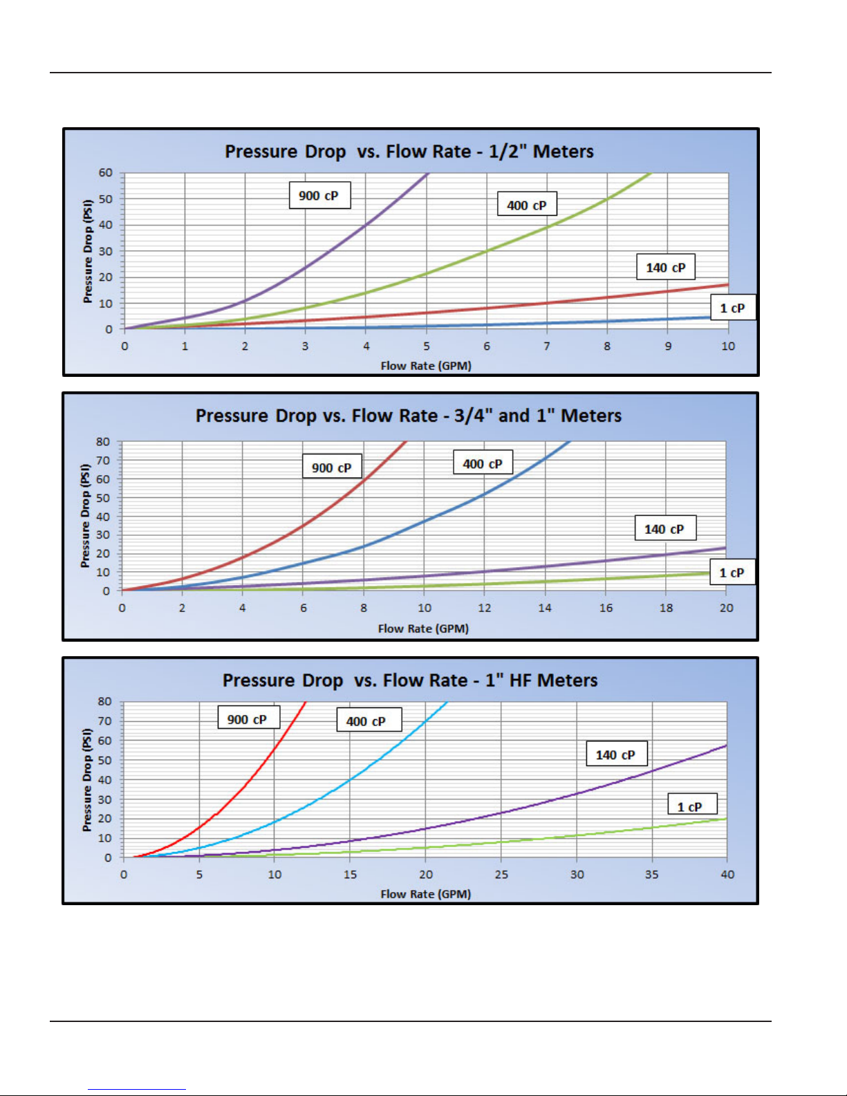
Upon initialization and continuation of fluids through the line and meter, the expected pressures are:
Page 7 February 2015 IOG-UM-00046-EN-09
Meter Operation
Pressure Drop vs Flow Rate
Page 8 February 2015IOG-UM-00046-EN-09
 Loading...