

Page 1

®
Badger Meter Europa GmbH
Registers type ILR7XX and
ILR7XXT
INSTALLATION AND
OPERATION MANUAL
May 2018
AC_ILR_BA_02_1805
Page 2

Contents Page
1. Basic safety recommendations ................................................................................... 1
2. Register operation ........................................................................................................ 3
2.1. Normal operation ................................................................................................. 3
2.2. Status................................................................................................................... 3
2.3. Totalizers ............................................................................................................. 3
2.4. Flow rate .............................................................................................................. 4
2.5. Battery ................................................................................................................. 4
2.6. Checksum ............................................................................................................ 4
2.7. Display scale factor .............................................................................................. 4
3. Register programming ................................................................................................. 5
3.1. Unit of measure .................................................................................................... 5
3.2. Scale factor .......................................................................................................... 5
3.3. Changing the meter pulse rate (for all ILR models with display) ........................... 6
3.4. Changing the register orientation (for all ILR models with display) ....................... 6
3.5. Changing the display mode (for all ILR models with display) ................................ 7
3.6. Exiting programming mode (for all ILR models with display) ................................ 7
4. Additional programming: Industrial analog and industrial pulse (ILR 710 & ILR750,
ILR750T, ILR701, ILR701T) ........................................................................................... 8
4.1. Pulse rate out ....................................................................................................... 8
4.2. Analog minimum flow rate .................................................................................... 9
4.3. Analog maximum flow rate ................................................................................... 9
4.4. Linearisation........................................................................................................10
5. Register output specifications & wiring.....................................................................11
5.1. Pulse (model ILR 710) ........................................................................................11
5.2. Dual pulse (model ILR 720) .................................................................................12
5.3. Pulse transmitter (model ILR 740) .......................................................................13
5.5. Pulse and analog output (model ILR750 and 750T) ............................................14
6. Return of goods for repair / Harmlessness declaration ............................................15
AC_ILR_BA_02_1805
Page 3

Basic safety recommendations Page 1/15
Failure to adhere to these safety instructions may result
in damage to the product or serious bodily injury.
1. Basic safety recommendations
Before installing or using this product, please read this instruction manual thoroughly.
Only qualified personnel should install and/or repair this product. If a fault appears,
contact your distributor.
Before the first installation
Please flush the meter with fresh water or the medium to measure before the first
installation.
Installation
Do not place any unit on an unstable surface that may allow it to fall.
Never place the units above a radiator or heating unit.
Route all cabling away from potential hazards.
Isolate from the mains before removing any covers.
Power connection
Use only the type of power source suitable for electronic equipment. If in doubt, contact
your distributor. Ensure that any power cables are of a sufficiently high current rating.
All units must be earthed to eliminate risk of electric shock.
Failure to properly earth a unit may cause damage to that unit or data stored within it.
Protection class
The device has protection class IP 65 and needs to be protected against dripping water,
water, oils, etc.
Setup & operation
Adjust only those controls that are covered by the operating instructions. Improper
adjustment of other controls may result in damage, incorrect operation or loss of data.
Cleaning
Switch off all units and isolate from mains before cleaning.
Clean using a damp cloth. Do not use liquid or aerosol cleaners.
Repair of faults
Disconnect all units from power supply and have it repaired by a qualified service person if
any of the following occurs:
If any power cord or plug is damaged or frayed
If a unit does not operate normally when operating instructions are followed
If a unit exposed to rain/water or if any liquid has been spilled into it
If a unit has been dropped or damaged
If a unit shows a change in performance, indicating a need for service.
AC_ILR_BA_02_1805
Page 4

Basic safety recommendations Page 2/15
RoHs
Our products are RoHs compliant.
Battery disposal
The batteries contained in our products need to be disposed of as per your
local legislation acc. to EU directive 2006/66/EG.
AC_ILR_BA_02_1805
Page 5
Register operation Page 3/15
2. Register operation
The following describes register operation and program settings for the industrial oval
gear series registers: Industrial Standard (ILR 700 / 701 / 701T), Industrial Pulse (ILR 710
/ 750 / 750T), Industrial Quadrature/Dual Pulse (ILR 720) and the Industrial Analog
(ILR 750 / 750T).
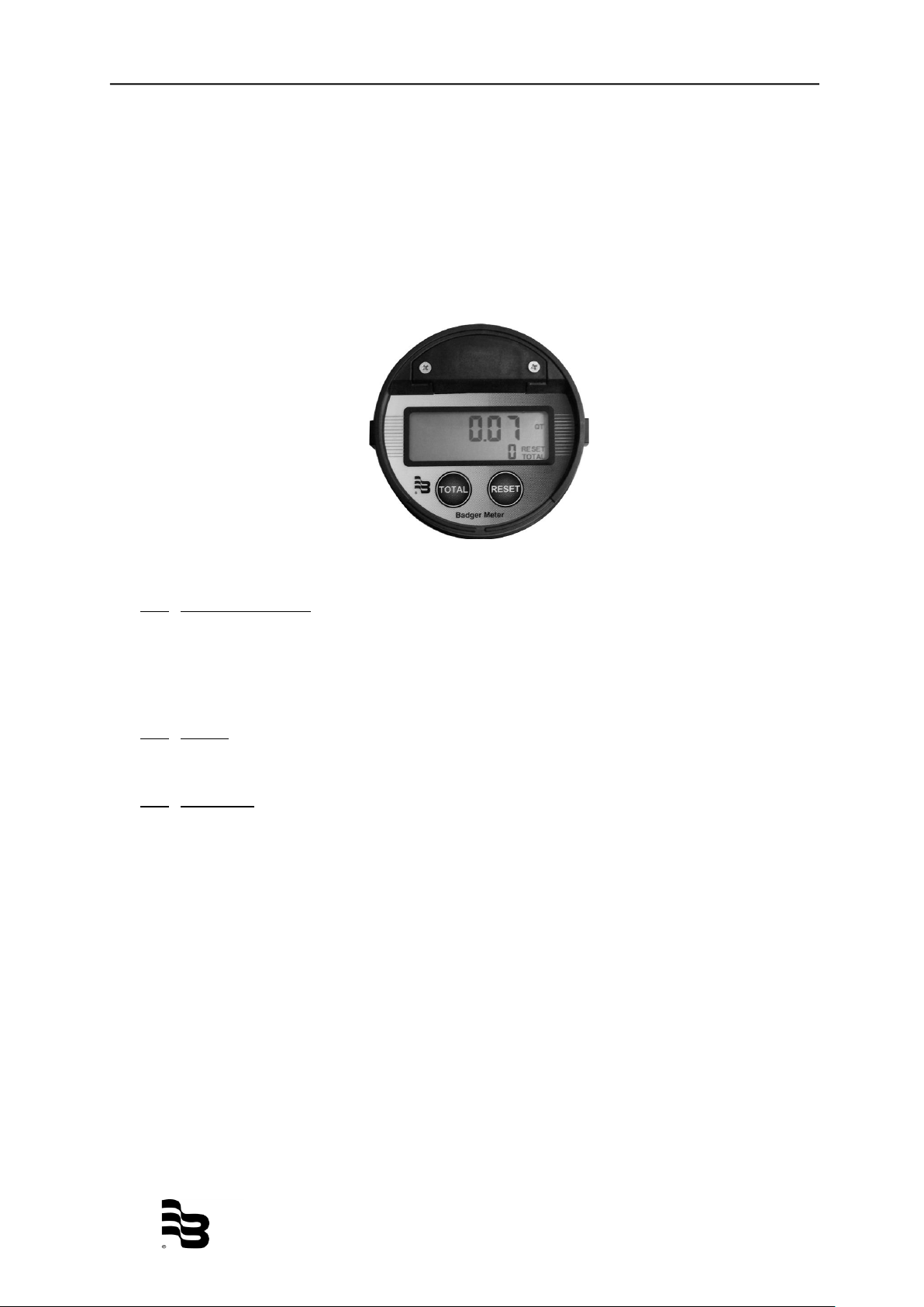
The register display consists of two rows of seven-segment digits, status, unit of measures, flow rate, and battery indicators. Operating function settings and programming are
provided using the TOTAL and RESET buttons.
Figure 3: Register display and button
2.1. Normal operation
(for models ILR 7XX)
To enter normal operation mode - when the screen is blank after exiting
programming mode, or upon initial use, press either the TOTAL or RESET button
once.
2.2. Status
The status indicators are RESET and TOTAL.
2.3. Totalizers
The top row of indicators is the batch totalizer. This totalizer displays the cumulative
volume of flow through the meter with six digits. The batch totalizer totalizes in
selected units of measure.
To reset the batch totalizer, after 2 seconds of no flow, press and release the
RESET button.
NOTE: For the ILR 720 model only, the batch totalizer can be reset by a low pulse on the
external reset input.
The bottom row of indicators display the resettable totalizer with five digits or the five
least significant digits of the non-resettable totalizer. RESET and TOTAL is indicated
when the resettable total is displayed in the five-digit lower row. Only TOTAL is
indicated when the non-resettable total is displayed.
To toggle between the non-resettable totalizer and the resettable totalizer, press and
release the TOTAL button.
AC_ILR_BA_02_1805
Page 6

Register operation Page 4/15
LBat
To reset the resettable totalizer, press and hold the TOTAL button and then press and
release the RESET button.
To display 11-digit non-resettable totalizer, while the non-resettable total is
displayed, press and hold the TOTAL button for seconds. The top row displays
the 6 most significant digits; the bottom row displays five least-significant
digits.
NOTE: The non-resettable totalizer normally displays 5 least-significant digits.
2.4. Flow rate
PER MIN is displayed in conjunction with the unit of measure. All flow rates are
calculated in volume unit per minute.
2.5. Battery
The "LBat" indicator will indicate when the battery is approaching end of life. When
the indicator is illuminated, the 2/3AA, 3.0 VDC lithium battery is drained to 10% of
its total capacity and should be changed. Normal battery life is five years.
Note: A 2/3AA, 3.6 VDC battery may also be used as a replacement.
Figure 4: Low battery indicator
2.6. Checksum
To display the firmware checksum, press and hold the RESET button for three
seconds. To return to normal display, release the RESET button.
2.7. Display scale factor
To display the scale factor:
At the same time, press and hold the TOTAL and RESET buttons for two seconds
to display the programmed scale factor. To return to the normal display, release
both buttons.
AC_ILR_BA_02_1805
Page 7

Register programming Page 5/15
3. Register programming
In programming mode only, pressing and releasing the TOTAL button advances to the
next parameter on the current screen. Pressing and releasing the RESET button changes
the current flashing selection to another selection (such as “L” to “GAL”).
To enter the programming mode, press the TOTAL button three times and
then press the RESET button three times (the time lag between pressing
both buttons six times must be within two seconds).
Changing the unit of measure and scale factor
(for all ILR models with display)
3.1. Unit of measure
Figure 5: Unit of measure & scale factor programming
1. Press and release the RESET button to change the unit of measure (L,
GAL, QT, PT).
2. Press and release the TOTAL button to select desired the unit of measure
(the selected unit of measure will flash).
3. When the appropriate unit of measure is selected, press the TOTAL button
to advance to the scale factor programming.
3.2. Scale factor
(for all ILR models with display)
The register collects input pulses from the oval gear meter and then determines the
appropriate display output using the scale factor. This scale factor varies depending
upon the viscosity of the liquid being measured, therefore calibrating the meter and
register in the appropriate liquid will affect the scale factor. The scale factor is
displayed as 5 digits (on the top row) next to the unit of measure. The scale factor
consists of 1 integer digit and 4 decimal digits (see figure 5).
1. Press the TOTAL button to select a digit (selected digits flash). After cycling
through all 5 digits of the scale factor, the register will return to the unit of
measure selection.
2. Press RESET to change the selected digit. The scale factor must fall
between the values of 0.5000 and 2.0000. The Badger Meter factory preset
is set between those values at 1.0000.
3. When finished adjusting the unit of measure and scale factor, press and hold
the TOTAL button for one second to advance to the Pulse Rate section.
NOTE: Error checking will not allow the user to advance to the next screen.
AC_ILR_BA_02_1805
Page 8

Register programming Page 6/15
Flow
direction
Inline
Perpendicular
3.3. Changing the meter pulse rate (for all ILR models with display)
The meter pulse rate (screen is indicated by the “I” on the top row, on the left side)
is the number of pulses per unit of measure as detected by the register. The pulse
rate varies according to the type of attached meter. The bottom row consists of the
5-digit integer value of the meter pulse rate, whereas the top row consists of the 2digit decimal value of the meter pulse rate.
The meter pulse rate is entered in pulses per liter if the selected unit of measure is
liters. The meter pulse rate is entered in pulses per gallon if the selected unit of
measure is gallons, quarts or pints.
Figure 6: Meter Pulse Rate
1. Press the TOTAL button to select a digit (selected digits flash). Press
RESET to change the selected digit. The pulse rate can be any value
between 00000.01 and 99999.99 on the top row; integer values are
displayed on the bottom row. Example: 10.45 would display .45 on the top
row and 10 would be displayed on the bottom row.
2. When finished adjusting the pulse rate, press and hold the TOTAL button for
one second to advance to the “register orientation” section.
NOTE: Error checking will not allow the user to advance to the next screen.
3.4. Changing the register orientation (for all ILR models with display)
For oval gear meters: Depending on the orientation perpendicular or inline on the
meter. For remote version, this will be set to “o”.
For nutating disc meters (RCDL) set to “o”.
For turbine meters (Vision) set to “o”.
Figure 7: Register orientation
1. Press the RESET button to toggle between available options (“I, for an
inline-to-flow orientation and “P” for a perpendicular-to-flow orientation or “o”
for Remote versions and for the RCDL-nutating disc meters and the Vision
turbine meters).
2. When finished adjusting the register orientation, press and hold the TOTAL
button for one second to advance to the “Default Display” section.
AC_ILR_BA_02_1805
Page 9

Register programming Page 7/15
3.5. Changing the display mode (for all ILR models with display)
The display mode screen (indicated by a “d” on the top row, on the left side)
determines the information displayed on the top line of the register during normal
operation. The display mode may be either the totalizer screen or the flow rate
screen.
“C,” indicates the totalizer screen and “F” indicates the flow rate screen. The
totalizer screen is depicted below:
Figure 8: Default display
1. While a letter is flashing on the display, press the RESET button to select
either totalizer or flow rate.
2. Upon completion of this setting, the programming of the industrial standard
register and the industrial dual pulse output is complete. For ILR 710,
ILR701, ILR701T, ILR750 and ILR750T models, see additional programming
parameters.
3.6. Exiting programming mode (for all ILR models with display)
To exit the programing mode:
1. On any screen, press and hold the both the TOTAL and RESET buttons.
The screen will revert back to the programmed scale factor, and then flash.
Following the three flashes, the register display will be blank.
Note: Pressing the TOTAL or RESET buttons will turn the display back on.
AC_ILR_BA_02_1805
Page 10

Additional programming: Industrial analog and industrial pulse Page 8/15
Figure 9: Output pulse lenght screen
Figure 10: Pulse rate out screen
4. Additional programming: Industrial analog and industrial pulse (ILR 710 & ILR750, ILR750T, ILR701, ILR701T)
Output pulse lenght
(for models ILR 710, ILR750 and ILR750T)
Indicated by a “P” on the left hand side of the display, this screen allows the selection of
the low duration of the output pulse.
• “0” for zero milliseconds (pulse output is disabled)
• “2” for 2 milliseconds
• “10” for 10 milliseconds
• “20” for 20 milliseconds
• “40” for 40 milliseconds
• “100” for 100 milliseconds
To advance to the next programming screen, hold the TOTAL button.
About Output Pulse Length: The pulse rate duration should take into account the "Pulse
Rate Out" and maximum meter flow rate, to prevent an output pulse duration greater than
the required time between pulses. The Output Pulse Length should be set to less than
the value of “t.”
Per the equation:
Maximum meter flow rate (in GPM or l/m)
t = ----------------------------------------------------------------- x 1000
60X output pulse rate
where t = the required pulse rate in milliseconds.
The output pulse rate = the programmed parameter (default = 1.00 PPL/PPG)
The maximum meter flow rate = the maximum flow rate of the meter for the application.
4.1. Pulse rate out
(for model ILR 710, ILR750 and ILR750T)
Indicated by an “o” on the left hand side of the display, this screen allows selection
of the pulses output per liter or per gallon depending on unit of measure (0.01
PPL/PPG to 999 PPL/PPG).
The meter pulse rate is entered in pulses per liter if the selected unit of measure is
liters. The meter pulse rate is entered in pulses per gallon if the selected unit of
measure is gallons, quarts or pints.
To advance to the next programming screen, hold the TOTAL button.
NOTE: Error checking will not allow the user to advance to the next screen.
AC_ILR_BA_02_1805
Page 11

Additional programming: Industrial analog and industrial pulse Page 9/15
Figure 12: Analog maximum flow rate screen
Figure 11: Analog minimum flow rate screen
4.2. Analog minimum flow rate
(for models ILR750 and ILR750T)
Indicated by a “L” on the left hand side of the display, this screen allows the setting
of the flow rate that corresponds to the 4mA output:
NOTE: The minimum flow rate value must be less that the maximum flow rate value.
• Minimum 0.0 LPM/GPM
• Maximum 100.0 LPM/GPM
• Default 0.0 LPM/GPM
NOTE: Error checking will not allow the user to advance to the next screen.
To advance to the next programming screen, hold the TOTAL button for one
second.
4.3. Analog maximum flow rate
(for models ILR750 and ILR750T)
Indicated by a “H” on the left hand side of the display, this screen allows the setting
of the flow rate that corresponds to the 20mA output:
NOTE: The maximum flow rate value must be greater than the minimum flow rate value.
• Minimum 0.0 LPM/GPM
• Maximum 100.0 LPM/GPM
• Default 30 LPM / 8 GPM
To advance to the next programming screen, hold the TOTAL button.
NOTE: Error checking will not allow the user to advance to the next screen.
AC_ILR_BA_02_1805
Page 12

Additional programming: Industrial analog and industrial pulse Page 10/15
Figure 13: Linearisation point 1 (of 9)
Figure 14: Linearisation point 9 (of 9)
4.4. Linearisation
(for models ILR701, ILR701T, ILR750 and ILR750T)
Indicated by 1 – 9 on the left hand side of the display, followed by a hyphen (-), this
screen allows the setting of the linearisation (in total 9 points).
Press the TOTAL button to select a digit (selected digits flash). Press RESET to
change the selected digit. The flow rate will be set in the top row of the meter and is
displayed in the unit you selected at step 9.1 (unit of measure). In the sample shown
above this would be the flow rate 0.4 liter per minute. On the bottom line of the meter
you can set in the correction of the error in %. In the sample below, the error at a flow
rate of 0,4 liter per minute would be -7,82%; to correct this, +7,82% needs to be set in
(the plus symbol [+] will not be shown).
Once the adjustment of the linearisation is completed, press and hold the TOTAL
button for one second to advance to the next linearisation point.
Number 9 at the left hand side of the display shows the 9th linearisation point. The
sample shows a flow rate of 250.0 liter per minute and a deviation of the flow meter of
+0,15%. To correct this error, -0,15% needs to be set as correction.
Note:
- Minimum 3 linearisation points needs to be programmed.
- The flow rates do not have to be programmed from low to high; the software will
sort the flow rates automatically, no matter at which point (1-9) they are
programmed.
To exit the programming mode:
On any screen, press and hold both the TOTAL and RESET buttons. The screen
will revert back to the programmed scale factor, and then flash. Following the three
flashes, the register display will be blank.
Note: Pressing the TOTAL or RESET buttons will turn the display back on.
AC_ILR_BA_02_1805
Page 13

Register output specifications & wiring Page 11/15
Yellow
White
Brown
Ground
Pulse
output
Output
jumper
8-24V DC input
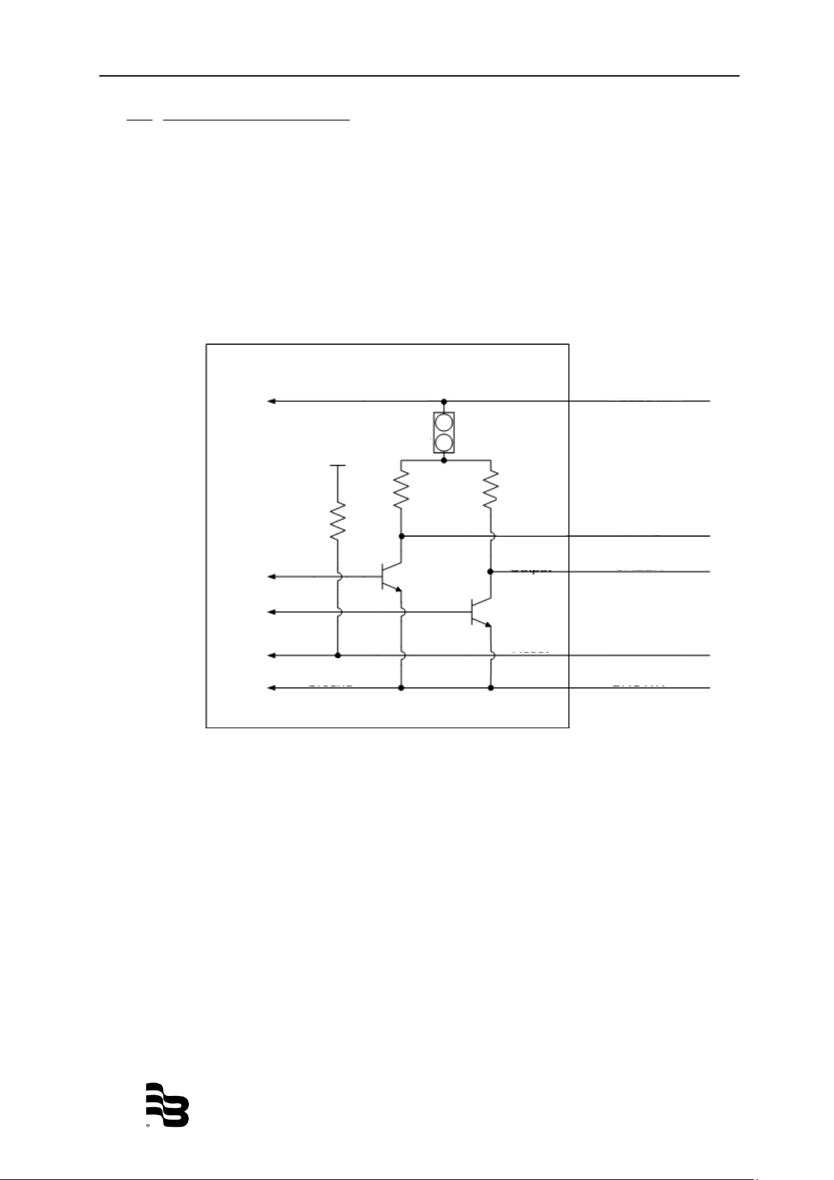
ILR 710
5. Register output specifications & wiring
5.1. Pulse (model ILR 710)
Register wiring
External DC+: Yellow
External ground: Brown
Pulse output: White
DC Input: 8 to 24 VDC; 20 to 40mA
Outputs: Pulse output with internal pull-up resistor; optional open collector output
with output jumper removal; pulse output is scalable in pulses per liter or pulses per
gallon.
Figure 13: ILR 710 wiring
AC_ILR_BA_02_1805
Page 14
Register output specifications & wiring Page 12/15
ILR 720
Yellow
White
Brown
Ground
Pulse
output
8-24V DC input
Green
Output
jumper
Grey
External
reset
Output
jumper
+3.0V DC
5.2. Dual pulse (model ILR 720)
Register wiring
External DC+: Yellow
External ground: Brown
Pulse output 1: White
Pulse output 2: Green
External reset: Grey
DC input: 8 to 24 VDC; 20 to 40mA
Outputs: Dual-pulse output with internal pull-up resistor; optional open collector
output with output jumper removed; dual pulse output forms a quadrature signal for
direction of flow.
Inputs: External reset pulled low to reset the batch totalizer.
Figure 14: ILR 720 wiring
AC_ILR_BA_02_1805
Page 15

Register output specifications & wiring Page 13/15
Meter
Pulse
per gallon
Pulse
per liter
½”
378.5
100
¾”
249.8
66
1”
249.8
66
1” HF
162.8
43
1 ½”
64.4
17
2”
34.1
9
3”
11.4
3
ILR 740
Green
White
Figure 17: ILR 740 wiring
Figure 16: Pulse transmitter
5.3. Pulse transmitter (model ILR 740)
Orientation: The register must be mounted as delivered. The transmitter will not
function if mounted differently.
Transmitter wiring
Reed switch outputs: Green and white.
Ratings: Max power: 10W (not to exceed!); max. voltage: 200 VDC/peak AC; max.
current: 0.5A DC/peak AC.
Outputs: Raw reed switch output with no signal conditioning.
Pulse per unit of measure (IOG series)
Note: Actual pulses per unit of measure are listed on the calibration certificate
provided with the meter.
AC_ILR_BA_02_1805
Page 16

Register output specifications & wiring Page 14/15
5.5. Pulse and analog output (model ILR750 and 750T)
Register wiring
External DC+ : Yellow
External ground : Brown
Pulse output : White
Analog output : Green
DC input : 8 to 24 VDC; 20 to 40mA
Outputs:
- Analog 4 to 20mA output in loop powered configuration; external load of 50 ohms
to 250 ohms; flow rate is linear scaled between 4mA minimum and 20mA maximum
set points; flow rates below programmed minimum read 4mA.
- Pulse output with internal pull-up resistor; optional open collector output with
output jumper removal; pulse output is scalable in pulses per liter or pulses per
gallon.
Figure 18: ILR 750 / 750T wiring
AC_ILR_BA_02_1805
Page 17

Return of goods for repair / Harmlessness declaration Page 15/15
6. Return of goods for repair / Harmlessness declaration
Please refer to our claims return form/harmlessness declaration under
www.badgermeter.de/service/return of goods.
AC_ILR_BA_02_1805
Page 18

®
Hotline
Phone +49-7025-9208-0 or -46
Fax +49-7025-9208-15
Badger Meter Europa GmbH
Subsidiary of Badger Meter, Inc., USA
Nürtinger Strasse 76
72639 Neuffen (Germany)
E-mail: badger@badgermeter.de
www.badgermeter.de
 Loading...