

Page 1
CM-6001-TM Manual
SERIES 12
VARIABLE AREA FLOWMETERS
INSTALLATION, OPERATION &
SERVICE INSTRUCTIONS
15555 North 79th Place
Scottsdale, AZ 85260
tel: (480) 922-7446
fax: (480) 948-3610
Email: sales@cox-instruments.com
Web: www.cox-instruments.com
Page 2

Contents
Section Page
I USE AND MAINTENANCE…………………………………… 1
1-1. Purpose ………………………………………… 1
1-3. Models ………………………………………….. 1
1-6. Variations Within Models …………………….. 1
1-9. Description …………………………………….. 1
1-24. Specifications ………………………………….. 4
1-27. Preparation for Use …………………………… 4
1-29. Installation ……………………………………… 4
1-30. Operation ………………………………………. 5
1-38. Maintenance …………………………………… 6
1-40. Cleaning Tubes and Floats ………………….. 6
1-42. Parts Replacement ……………………………. 6
1-44. Replacing Tube Gaskets ……………………... 6
1-48. Replacing Valves ……………………………… 7
1-50. Shipment ……………………………………….. 8
1-52. Storage …………………………………………. 8
1-54. Trouble Shooting ……………………………… 8
1-55. Back Lighting Maintenance ………………….. 9
Flowmeter Model Conversion Key 10
II PARTS BREAKDOWN………………………………………... 13
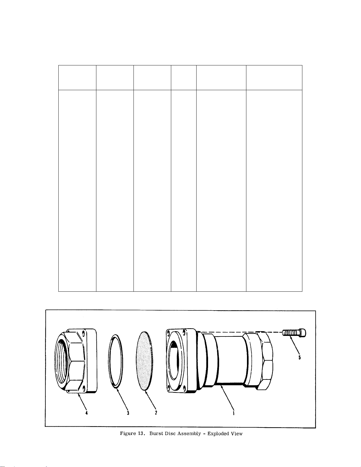
Figure 13. Burst Disc Assembly – Exploded View …… 13
Figure 14. Inlet Elbow Assembly …………………………. 13
Figure 15. Tube Assembly – Exploded View …………… 14
Figure 16. Worcester Valve and Handle Assembly ……. 15
Page 3

SECTION I
USE AND MAINTENANCE
Section I
Paragraphs 1-1 to 1-10
1-1. PURPOSE.
1-2. The Series 12 flowmeter is an instrument for the accurate
and continuous measurement of the rate of flow for liquids
and gases at nominal pressures.
1-3. MODELS.
1-4. The Series 12 flowmeter is available in three basic
models; Model 124, Model 129 and Model 120. (Refer to
Flowmeter Model Conversion Key, Page 9). Each model is
available as a single stage or multi-stage flowmeter. Each
stage consists of a matched tube and float with a calibrated
scale and necessary mounting connections. A multi-stage
flowmeter consists of two or more matched tubes and floats,
normally of the same model together with scales and mounting
connections, assembled into a steel shell.
1-5. Bypass valves are required for most multi-stage
flowmeters to bypass the lower stages when operating in the
higher flow ranges, thus maintaining a normal pressure drop
over the entire flow range.
NOTE
On a maximum stage standard flowmeter of
any model, the pressure drop through the
flowmeter will not exceed 6 psig, except for
flowmeters with bypass orifice sections
where the pressure drop is approximately 8
psig.
b. Orifice valve and calibrated auxiliary bypass
orifice to increase the capacity of a particular
flowmeter.
1-9. DESCRIPTION.
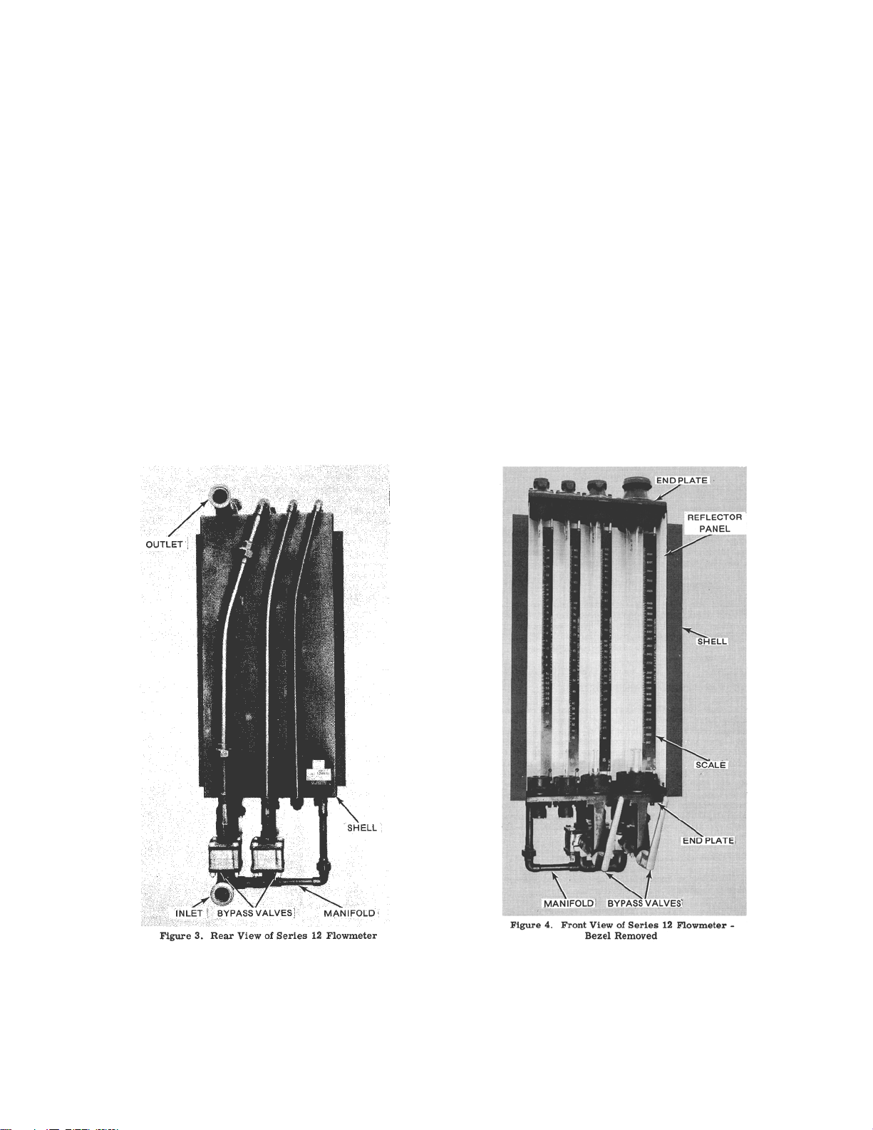
1-10. In multi-stage flowmeters the top of each glass tube is
connected with the bottom of the next larger tube by a
copper tube at the rear of the shell. This provides a
continuous passage from inlet at the lower end of the
first tube to the outlet at the top of the last tube (see fig.
3). Each tube is fitted with a metal float which
positions itself in the tube according to the rate of flow.
Since the pressure drop across the float is constant
throughout the range of any particular tube, any change
in rate of flow will result in a relocation of the float to a
position where the annulus area is such as to maintain
this constant pressure drop across the float. Since the
tube is of an expanded taper, an increase in flow will
result in a rise in the float position and inversely a
decrease in flow will result in a lowering of the float
position. When the maximum capacity of a tube is
approached, the increased rate of flow affects the float
in the next tube. This sequence is continued through all
tubes until one of the floats comes to rest within the
limits of its scale at which point the rate of flow is read.
Tubes are calibrated and scales are engine divided to
read in pounds per hour, gallons per minute or other
units to fit specific requirements.
1-6. VARIATIONS WITHIN MODELS.
1-7. Multi-stage flowmeters usually consist of tubes of the
basic model as in paragraph 1-4, but to meet certain
requirements, some multi-stage flowmeters have been
produced with intermixed size 40, 90, 100 and 140 tubes.
Other requirements have resulted in incorporating size 60
tubes intermixed with one or more of the standard Series 12.
To correctly identify any tube refer to the number etched near
the top of the tube. This number consists of the flowmeter
serial number, tube size, and model number. For example,
12001-47 indicates flowmeter serial number 12001-47 and
tube size seven in the Model 124-300 group.
1-8. Other variations within models are:
a. Fluorescent backlighting for each and
convenience in reading flow.
1
Page 4
Section I
Paragraphs 1-11 to 1-13
1-11. TUBES (fig. 2). Tubes are precision molded of
borosilicate glass with four float guides and tapered flutes
integral with the tube. The inner diameter across the guides is
the same from top to bottom but the inner diameter of the
tapered flutes expands logarithmically giving an increasing
flow area past the float as it rises. The guides confine the float
to the central axis of the tube and diminish swirls of fluid
passing through the tube. Tubes have flowmeter serial
number and tube size etched near the top of the tube.
NOTE
Tubes, floats, and scales are calibrated as a unit
and are not interchangeable. If a tube is broken,
a new tube, float, and scale must be ordered. An
unserviceable float can be replaced by fitting and
recalibrating a new float to the old tube.
Damaged scales can be replaced if flowmeter
serial number, tube number, and sizes are
furnished.
1-12. FLOATS (fig. 2). Floats are machined of a material
impervious to the fluid used and precisely fitted to the tube
making a matched assembly of float and tube. Floats are
provided with a short threaded stub extension for attachment
of a rod to facilitate removal or installation. Floats are etched
with the flowmeter serial number and tube size.
1-13. SCALES (fig. 4). Each tube with its float is accurately
calibrated and its scale graduated to agree with the calibration.
The 18-inch logarithmic type scale provides the same degree
of reading accuracy throughout the flow range. Scales are
made of plastic or aluminum and engraved with contrasting
figures. Scales are attached to adjustable support posts which
2
Page 5
are located in drilled holes in front corners of the tube packing
glands and secured by screws. Scales are aligned with tube
index line by adjusting the support posts. Packing glands are
drilled at each side permitting scales to be mounted on both
sides if desired.
1-14. TUBE MOUNTING (fig. 15). Tubes are fitted into
upper and lower end castings and are held in position by
packing glands. The glands are tightened against gaskets to
prevent leakage. The end caps mounted on lower and upper
end castings contain float stops with springs.
1-15. TUBE CONNECTIONS. End casting fittings extend
toward the back of the instrument and are connected in series
by copper tubing. Bottom fittings are provided with bypass
valves when required. The fluid enters a manifold assembly at
the bottom and is then distributed as governed by the position
of the bypass valves. Outlet is from the top of the last tube.
Section I
Paragraphs 1-14 to 1-21
1-18. A 2-inch orifice ball valve is provided, in flowmeters, to
divert a portion of the flow through the calibrated orifice
increasing the flow range of the instrument. Flowmeters
incorporating a bypass orifice are provided with a special inlet
elbow to eliminate entrance effects.
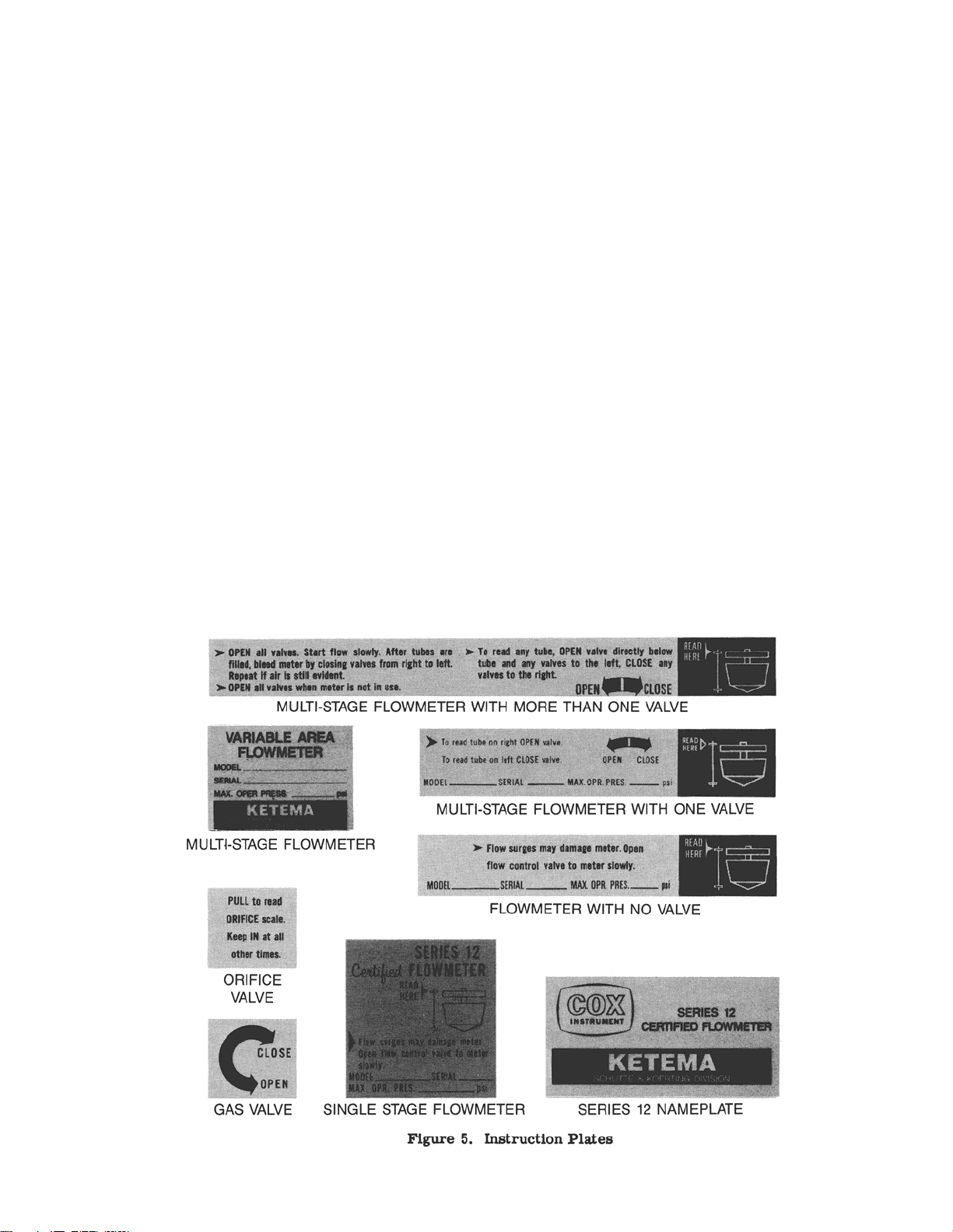
1-19. INSTRUCTION PLATE. An instruction plate,
mounted behind the bezel window provides instructions for
operating the flowmeters and reading the position of the float.
1-20. SHELL. All tubes and fittings are mounted in a welded
steel shell. End castings are bolted to upper and lower
members. Shells are designed for flush panel mounting. A
bezel holding a safety glass window covers the front of the
instrument. A white enameled steel reflector panel is mounted
behind the tubes. Valve shafts extend through the bezel.
Handles are installed on the ends of the valve shafts.
1-16. The ball type bypass valve is manufactured by the
Worcester Valve Co. and is furnished in ¾, 1-1/4 and 2-inch
sizes.
1-17. The valve consists of a bronze body and ball with Buna
N seals to prevent leakage. One end of the handle assembly,
available in varying lengths, is connected to the valve by a
coupling while the bracket on the opposite end is connected to
the shell.
1-21. BURST DISC ASSEMBLY. A burst disc assembly can
be furnished to protect the flowmeter tube in installations
where the flowmeter might be subjected to excessive pressure
surges. This disc assembly is furnished as standard equipment
on any flowmeter incorporating a 48, 99, 109 or 148 size tube
and can also be ordered for any particular flowmeter. The disc
assembly is installed in a tee on the inlet side of the
3
Page 6
Section 1
Paragraphs 1-22 to 1-29
flowmeter and is designed to burst at a pressure lower than the
bursting pressure of the largest tube. The disc is rated to burst
at 85 psi. r 5 psi. This provides a bypass through which the
flow may be returned to the supply tank.
1-22. LIGHTS. Depending on size and number of stages
used, flowmeters can be equipped with explosion proof or
non-explosion proof fluorescent lights mounted behind the
tubes.
1-23. AIR CYLINDERS. Flowmeters can be equipped with
air cylinders to operate the bypass valves. Different cylinder
assemblies are used for 1-1/4 and 2-inch valves.
1-24. SPECIFICATIONS.
1-25. CAPACITY. Cox Variable Area Flowmeters Bulletin
CA 6001 provides information on the range and capacity for
all standard combinations of Series 12 Flowmeters.
1-26. MOUNTING DIMENSIONS. Cox Variable Area
Flowmeter Bulletin CA 6001 provides information on
mounting dimensions for all standard Series 12 Flowmeters.
1-27. PREPARATION FOR USE.
1-28. UNPACKING. Unpack instrument carefully. Parts of
this flowmeter are fragile and can be easily damaged. Check
all parts against packing slip to be sure that none are
discarded. Floats, 0.375-inch and larger, are packed
separately in a small container. Handle floats carefully.
Floats are fitted to the tubes with extreme accuracy and the
slightest damage may make them useless. Replace them in
original containers after checking until ready for their
installation.
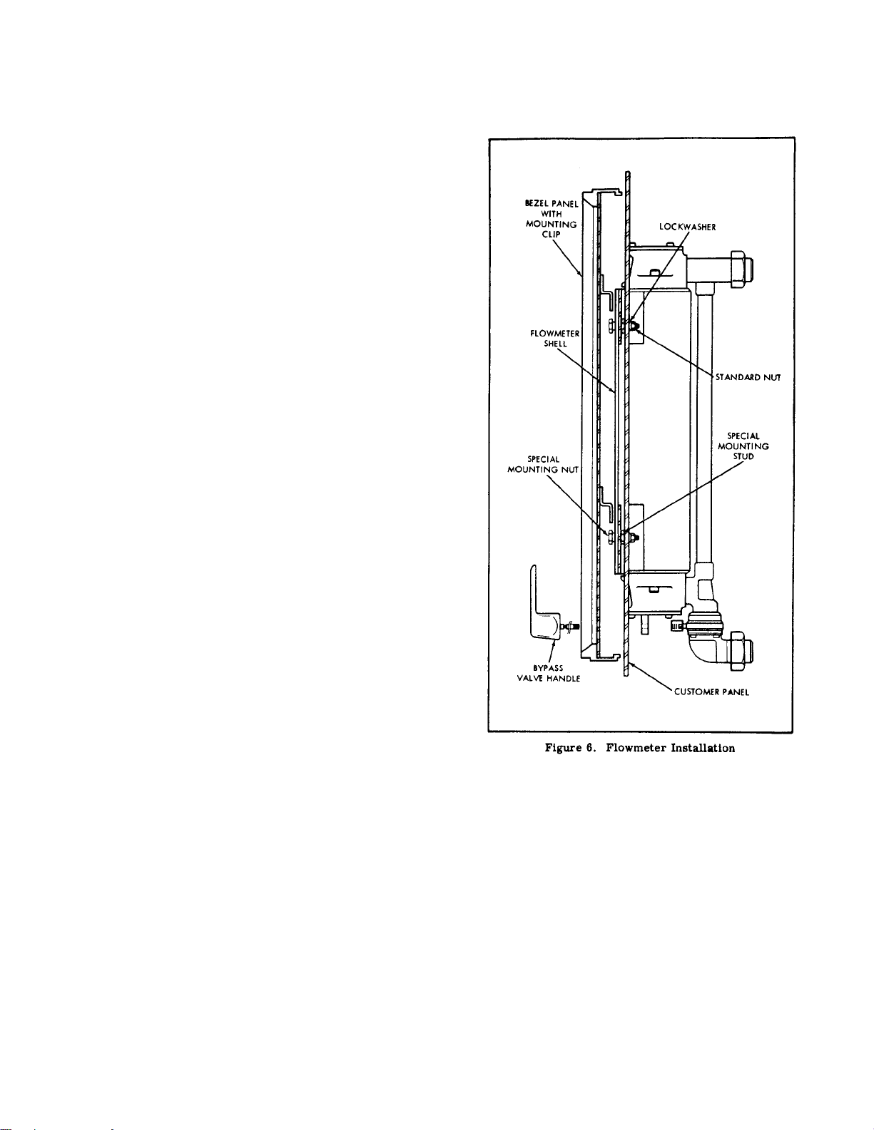
1-29. INSTALLATION (fig. 6).
a. Flowmeter should be mounted in a vertical position and as
free from vibration as possible. The maximum allowable
position is approximately 5q off the center vertical centerline.
A position greater than 5q would tend to introduce about a 1 to
2% error in accuracy. Install special mounting stud (longer
threaded portion first) into holes drilled in customer’s panel.
Secure in place with lockwasher and standard hex nut. Install
meter shell onto studs and secure in place with special nut
with shoulder toward panel.
b. Clean inside of instrument thoroughly. Wipe reflector with
a clean cloth. The red index line on scale must align with red
mark on tube. Loosen set screws holding scale support posts
in packing glands and adjust scales if necessary. Install bezel
with window on front of shell by engaging clips on inside of
bezel in special mounting studs.
c. To avoid strain and transmitting vibration to flowmeter,
flexible hoses or lines should be installed between flowmeter
and service lines. If inlet and outlet unions cannot be
separated by the fingers, use two wrenches. All tubing joints
are soft soldered and strain on them should be avoided. With
suitable adaptor, connect flexible lines to unions and service
piping. Use two wrenches to tighten. A shut-off valve should
be installed in discharge line beyond the flexible connection.
This will prevent possible drainage of the instrument when
device being checked is disconnected. When furnished, install
pressure blowout disc assembly in inlet line to flowmeter.
d. A 25 micron filter should be installed on the inlet side of
the flowmeter. This will keep the flowmeter clean and keep
floats from sticking and collecting dirt. Collecting dirt adds
weight to the float which in turn changes flow rate reading.
4
Page 7

Section I
Paragraphs 1-30 to 1-37
In addition, a thermometer should be installed as close to the
inlet of the flowmeter as possible. This will provide a
constant check to assure proper flow readings.
e. The flowmeters are calibrated on a Cox Liquid Calibrator
maintaining a 10-15 psig back pressure. Back pressure should
be provided in the installation to aid in purging air out of the
system and introducing float stability.
f. Remove fillister head screws holding end caps to upper end
castings and lift off caps. Remove floats from their container
and wipe them off thoroughly with a clean soft cloth. Notice
that floats are etched with the serial number of instrument and
tube size. Thread the float extractor rod to each float, insert
float in proper tube and lower to bottom of tube. Unscrew
rod. Use care to get floats in proper tube. Install end caps
with their “O” rings and tighten screws. Clearance on panel
cut-out should be provided in the top of any test stand to allow
for float removal.
CAUTION
Do not drop floats into tubes.
1-30. OPERATION.
valve is opened, the tubes below it are inoperative and
pressure drop is maintained at a minimum. All valves must be
opened when reading last tube.
1-35. READING THE SCALES. Scales are read opposite top
surface of float disc. On units equipped with an orifice, read
the scale on the right side of the largest tube when the orifice
valve is opened. Readings are accurate only when eye of
observer is at the same level as top of float. (See fig. 5.)
1-36. TEMPERATURE. Watch temperature of liquid during
test. Endeavor to keep it within plus or minus 3qF of value
marked on scale. Three degrees Fahrenheit temperature
change is equal to approximately 0.1% shift in flow rate.
1-37. PRESSURE BLOWOUT DISC ASSEMBLY. If a
flowmeter utilizing a pressure blowout disc assembly has been
subjected to excessive pressure surges causing the blowout
disc to burst, the following procedure must be followed before
resuming operation.
1. Shut down fuel supply to flowmeter
1-31. GENERAL. The instrument has been accurately
calibrated for a specific liquid or gas and the scales divided
accordingly. Variations in temperature or in specific gravity,
which are marked on edges of scales, will affect correctness of
readings.
1-32. LEAKAGE. The equipment to be tested is normally
connected to the outlet of the instrument. The connections
between flowmeter and equipment must be tight. Any leakage
in this line will result in high readings. If the equipment to be
tested is installed on the inlet side, leakage will result in low
readings.
1-33. EXPEL AIR. Open the bypass valves and provide
means to return the maximum flow to fuel supply tank. Open
supply line to flowmeter and set up rate of flow corresponding
to full scale reading on largest tube, open and close largest
tube valve and allow to remove air. Reduce flow within range
of next largest tube following a bypass valve and repeat
procedure until all air is expelled. Continue in a like manner
until flowmeter is completely purged of air.
CAUTION
Do not operate valves until flowmeter is filled
with liquid. Always leave valve in “OPEN”
position when flowmeter is not in use.
1-34. VALVES. In a multi-stage flowmeter, all valves must
be closed when reading flow in the smaller tubes. As each
5
Page 8

Section I
Paragraphs 1-38 to 1-44
2. Determine cause of excessive pressure surges
and correct if possible.
this reason the repairs and replacements considered
are limited to replacement tube gaskets, valve seals,
metering tubes, and repair of damaged copper tubing.
3. Replace ruptured blowout disc.
1-38. MAINTENANCE.
1-39. GENERAL. Periodic cleaning of tubes and floats is
necessary to remove all deposit of foreign matter. A regular
schedule of cleaning should be adhered to depending on nature
of liquid being used. Deposits on floats or tube walls which
restrict flow will result in high readings.
1-40. CLEANING TUBES AND FLOATS
a. Relieve pressure on instrument. Do not drain.
b. Remove fillister head screws holding end cap to upper end
castings.
c. Insert float extractor rod (fib. 7), thread it onto float, and
lift out float. Handle floats carefully to avoid damage.
d. With the proper size brush, clean tube thoroughly with
eight or ten strokes of brush for entire length of tube (fig. 8).
e. Drain and flush with clean fluid.
f. Wipe float with clean soft cloth to remove all dirt and gum
deposit. Do not polish float with any abrasive.
1-44. REPLACING TUBE GASKETS (fig. 9).
a. Relieve pressure on instrument.
b. Remove top end caps and floats.
c. Remove end caps from bottom end castings to
drain unit.
d. Remove bezel with window from front of
instrument.
e. Remove screw holding scale to lower support
post. Loosen screw holding upper support post and
pull down to remove scale and upper support post.
f. Remove socket head cap screws holding glands in
position. Slip glands toward center of tube, lift tube
slightly and remove from instrument. Notice
arrangement of tube gaskets when removing. Note
that one aluminum backing washer, then the four or
five Buna N gaskets (to make ½-inch thickness) go
on tube and are slipped into gland in that order, then
the second aluminum washer is placed on the gaskets.
The thin fairprene gasket is then placed in gland.
g. Attach extractor rod and carefully lower float until float
rests on lower stop. Detach rod.
h. Install end cap and tighten screws. Clean remaining stages
in order.
NOTE
Use extreme care at all times to avoid damage to
float. Any damage will affect calibration of any
tube and result in inaccurate readings. Also be
sure that floats are not interchanged.
1-41. ALIGNMENT OF SCALES. Check alignment of
scales when cleaning tubes. Red index line on scale should
align with red index line on tube. If out of line, loosen screws
holding scale support posts, align scale and tighten screws.
1-42. PARTS REPLACEMENT.
1-43. PERMISSIBLE OVERHAUL. Flowmeters
are assembled and calibrated by trained personnel
under exacting conditions and no general
disassembly is ever required or recommended. For
6
Page 9

This thin gasket can be held in position by coating with a thin
film of cup grease to prevent shifting while assembling gland
and tube. A tube stop washer is then installed as the last item
in the bottom gland only.
CAUTION
Do not use cup grease on flowmeters for oxygen
service.
g. To assemble, place tube in position with aligning mark
toward front. Slip glands into position and secure with cap
screws. Tighten screws evenly.
h. Install scale and upper support post. Install screw holding
scale to lower support post. Align mark on scale with mark on
tube and tighten support post set screws.
i. Install lower end caps and tighten fillister head screws.
j. Install floats using rod to carefully lower float onto bottom
stop.
Section I
Paragraphs 1-45 to 1-49
k. Install upper end caps and tighten fillister had screws.
l. Install bezel with window to front of instrument.
1-45. REPLACING BROKEN METERING TUBE. As all
tubes are calibrated with their floats, and scales graduated to
conform, replacement tubes are supplied with floats, scales,
and necessary gaskets. For removal and replacement of tubes
refer to paragraph 1-44. Damaged scales can be replaced by
giving tube size and serial number of the flowmeter. This
number is etched on tube near the stop and on the float shank.
1-46. REPLACING FLOAT STOPS. Float stops are rods
threaded on one end and screwed into end caps. Stops are
equipped with springs. To replace, grip stop in vise and
unscrew end cap and install new stop. Spring can be
unscrewed from old stop and installed on replacement. When
replacing float stop, the stop and end cap must be square.
1
-47. REPAIRS TO METAL TUBING AND FITTINGS. No
one except a repairman thoroughly experienced and competent
in making solder joints should be permitted to make repairs or
replacements on the metal tubing.
WARNING
If the vapor of the liquid used in this instrument
is highly volatile, the instrument must be
thoroughly cleaned before any heat is used in
disassembly.
remove manifold. Remove cap screws from the upper flange
of the valves to be replaced and withdraw valves.
b. See that seals and seats are in position on both faces, insert
valve between flanges and install cap screws on top and
bottom flanges. Tighten upper screws and pull screws in
lower flange up evenly. Tighten inlet union. Connect handle
assembly to valve, utilizing pin and coupling.
1-48. REPLACING VALVES.
a. Disconnect inlet tube union to first stage and loosen all cap
screws in lower flanges holding manifold to valves and
7
Page 10

Section I
Paragraphs 1-49 to 1-54
1-49. REPAIR OF VALVES. If the valve becomes worn or
defective, replacement parts may be purchased from the
manufacturer. See Section II for detailed parts lists.
1-50. SHIPMENT.
1-51. The flowmeter should never be shipped unless carefully
boxed and fully protected. Floats, 3/8 inch and larger, must be
removed from tubes and wrapped separately to prevent
damage.
TROUBLE POSSIBLE CAUSE REMEDY
READINGS TOO HIGH Temperature of fuel below
specifications.
Viscosity of fuel higher than specified.
Dirty floats or metering tubes.
Leaks in gaskets in tubes of higher
capacity than tube being read.
1-52. STORAGE.
1-53. If flowmeter is to be placed in storage, fill tube with oil
SAE-10 and open all valves.
CAUTION
For oxygen service flowmeters, clean with
Freon after storage.
1-54. TROUBLESHOOTING.
Correct temperature.
Use specified fuel if possible.
Clean (par. 1-40).
Replace gaskets (par. 1-44).
Leak between instrument and test unit (if
Check for and repair leakage.
on outlet side).
READINGS TOO LOW Temperature of fuel above
Correct temperature.
specifications.
Viscosity of fuel lower than specified.
Leaks through bypass valves.
Leak between instrument and test unit (if
Use specified fuel if possible.
Check valves are correct.
Check for and repair leakage.
on inlet side).
READING INACCURATE
(EITHER HIGH OR LOW)
Reading taken improperly.
Scales improperly set.
Eye must be on level with float top
(par. 1-35).
Align scale and tube red index lines
(par. 1-41).
FLOATS FLUCTUATE Pump surge reaches instrument.
Air in system.
Install surge trap or change pump.
Bleed air (par. 1-33).
FLOAT STICKS IN TUBE Tube or float dirty. Clean (par. 1-40).
EXCESSIVE PRESSURE DROP
Closed bypass valves.
Check and correct valves.
THROUGH INSTRUMENT
Float sticks.
Clean float (par. 1-40).
8
Page 11

Section I
Paragraph 1-55 – 1-55
1-55. BACK LIGHTING MAINTENANCE. Bulb
replacement is accomplished as follows:
a. Non-Explosionproof (See figures 10 and 11)
1. Disconnect power and electrical wires to shell
assembly.
2. Remove four (4) screws (10-32 x 3/8) holding shell
assembly to housing.
3. Slide out shell assembly.
4. Remove and replace defective fluorescent bulb (G.E.
P/N F20T12/D) and/or starter (G.E. P/N FS-2) as required.
5. Slide shell on housing and align.
6. Reinstall screws removed in second step.
7. Reconnect electrical wires disconnected in first step.
b. Explosionproof (See figures 10 and 12)
1. Disconnect power, conduit, and electrical wires to
shell assembly.
5. Remove and replace defective fluorescent bulb (G.E.
P/N F15T12/CW) and/or starter (G.E. P/N FS-2) as required.
Maintenance instructions for this operation are printed on the
cap inside face.
6. Reinstall the cap removed in the fourth step.
7. Slide shell assembly on flowmeter housing and align.
8. Reinstall screws removed in second step.
9. Reconnect electrical wires and conduit disconnected in
first step.
2. Remove four (4) screws (10-32 x 3/8) holding shell
assembly to flowmeter housing.
3. Slide out shell assembly.
4. Remove upper cap (end opposite conduit connection)
by turning cap counter-clockwise.
9
Page 12

Section I
FLOWMETER MODEL CONVERSION KEY
MODEL SHELL NO. TUBE NUMBERS
124-200
124-201
124-202
124-203
124-204
124-205
124-206
124-207
8
14
15
3
4
5
6
7
141
141-142
141-142-143
141-142-143-144
141-142-143-144-145
141-142-143-144-145-146
141-142-143-144-145-146-147
141-142-143-144-145-146-147-148
RECOMMENDED
SAFE WORKING
PRESSURE (psig)
200
200
160
14
110
95
70
65
124-208
124-209
124-210
124-211
124-212
124-213
124-214
124-215
124-216
124-217
124-218
124-219
124-220
124-221
124-222
124-223
124-224
124-225
124-226
124-227
124-228
124-229
14
10
8
2
3
4
5
6
9
1
2
4
5
6
9
1
3
4
6
2
3
5
142
142-143
142-143-144
142-143-144-145
142-143-144-145-146
142-143-144-145-146-147
142-143-144-145-146-147-148
143
143-144
143-144-145
143-144-145-146
143-144-145-146-147
143-144-145-146-147-148
144
144-145
144-145-146
144-145-146-147
144-145-146-147-148
145
145-146
145-146-147
145-146-147-148
200
160
140
110
95
70
65
160
140
110
95
70
65
140
110
95
70
65
110
95
70
65
10
124-230
124-231
124-232
124-233
124-234
11
12
146
2
4
3
146-147
146-147-148
147
147-148
95
70
65
70
65
Page 13

FUEL
(120 – 200
to 120 – 222)
FLOWMETER MODEL CONVERSION KEY – CONTINUED
OIL
(120 – 240
to 120 – 261)
GASES
(120 – 277
to 120 – 294)
SHELL
NO. TUBE NUMBERS
Section I
RECOMMENDED
SAFE WORKING
PRESSURE (psig)
LIQUIDS GASES
120-200
120-201
120-202
120-203
120-204
120-205
120-206
120-207
120-208
120-209
120-210
120-211
120-212
120-213
120-214
120-215
120-216
120-217
120-218
120-219
120-220
120-240
120-241
120-242
120-243
120-244
120-245
120-246
120-247
120-248
120-249
120-250
120-251
120-252
120-253
120-254
120-255
120-256
120-257
120-258
120-259
120-277
120-279
120-280
120-281
120-282
120-283
120-284
120-285
120-286
120-287
120-288
120-289
120-290
120-291
120-292
120-293
10
11
12
12
12
8
8
8
1
3
3
8
1
3
3
9
2
2
9
2
2
3
3
61
65
102
102-105
102-105-108
102-105-108*
103
103-106
103-106-109
103-106-109*
104
104-107
104-107*
105
105-108
105-108*
106
106-109
106-109*
107
107*
108
108*
270
260
210
140
75
75
175
110
65
65
170
95
95
140
75
75
110
65
65
95
95
75
75
180
170
140
90
50
-
115
70
50
-
110
60
-
90
50
-
70
50
-
60
-
50
-
120-221
120-222
FUEL
(129 – 200
to 129 – 234)
129-200
129-201
129-202
129-203
129-204
129-205
129-206
129-207
129-208
129-209
129-210
* 2-inch orifice valve
** No. 1 shell used
120-260
120-261
OIL
(129 – 240
to 129 – 271)
129-240
129-241
129-242
129-243
129-244
129-245
129-246
129-247
129-248
120-294
GASES
(129 – 277
to 129 – 304)
129-277
129-279
129-280
129-281**
129-282
129-283
129-284
129-285
129-286**
129-287
129-288
13
13
SHELL
NO.
8
8
8
14
2
3
5
5
8
14
2
4
4
109
109*
TUBE NUMBERS
61
65
91
91-93
91-93-95
91-93-95-97
91-93-95-97-99
91-93-95-97-99*
92
92-94
92-94-96
92-94-96-98
92-94-96-98*
65
65
RECOMMENDED
SAFE WORKING
PRESSURE (psig)
LIQUIDS GASES
270
260
210
175
140
90
65
65
210
170
110
75
75
50
-
180
170
140
115
90
60
50
-
140
110
70
50
-
11
Page 14
Section I
FUEL
(129 – 200
to 129 – 234)
FLOWMETER MODEL CONVERSION KEY – CONTINUED
RECOMMENDED
OIL
(129 – 240
to 129 – 271)
GASES
(129 – 277
to 129 – 304)
SHELL
NO.
TUBE NUMBERS
SAFE WORKING
PRESSURE (psig)
LIQUIDS GASES
129-211
129-212
129-213
129-214
129-215
129-216
129-217
129-218
129-219
129-220
129-221
129-222
129-223
129-224
129-225
129-226
129-227
129-228
129-229
129-230
129-231
129-232
129-233
129-234
129-249
129-250
129-251
129-252
129-253
129-254
129-255
129-256
129-257
129-258
129-259
129-260
129-261
129-262
129-263
129-264
129-265
129-266
129-267
129-268
129-269
129-270
129-271
129-289
129-290
129-291
129-292
129-293
129-294
129-295
129-296
129-297
129-298
129-299
129-300
129-301
129-302
129-303
129-304
10
11
12
12
12
13
13
8
1
3
5
5
9
1
3
3
9
2
4
4
2
2
3
3
93
93-95
93-95-97
93-95-97-99
93-95-97-99*
94
94-96
94-96-98
94-96-98*
95
95-97
95-97-99
95-97-99*
96
96-98
96-98*
97
97*
97-99
97-99*
98
98*
99
99*
175
14
90
65
65
170
110
75
75
140
90
65
65
110
75
75
90
90
65
65
75
75
65
65
115
90
60
50
-
110
70
50
-
90
60
50
-
70
50
-
60
-
50
-
50
-
50
-
12
* 2-inch orifice valve
Page 15

SECTION II
PARTS BREAKDOWN
Section II
Parts Breakdown
FIGURE
AND
INDEX NO.
13-
-1
-2
-3
-4
-5
14-
-1
-2
PART
NUMBER DESCRIPTION
25861
25862
85309
AN6230-8
25867A
5 / 16-24 x 1
36638
36634
No Number
No Number
AN6230-4
AN6230-13
BURST DISC ASSEMBLY
STRAINER ASSY
BLOWOUT DISC
“O” RING
THREADED END FLANGE
SOCKET HEAD SCREW
INLET ELBOW ASSY, 2-inch
INLET ELBOW ASSY, 3-inch
INLET ELBOW, 2-inch
INLET ELBOW, 3-inch
“O” RING, 2-inch elbow
“O” RING, 3-inch elbow
QTY
PER
ASSY
1
1
1
1
1
4
1
1
1
1
1
1
13
Page 16

Section II
Parts Breakdown
14
Page 17

Section II
Parts Breakdown
FIGURE
AND
INDEX NO. DESCRIPTION
16-1
-2
-3
-4
-5
-6
WORCESTER VALVE*
ROLL PIN
COUPLING
PIN
BRACKET
HANDLE ASSEMBLY
WITHOUT LIGHT SHELL
WITHOUT LIGHT SHELL
WITHOUT LIGHT SHELL
WITH LIGHT SHELL
WITH LIGHT SHELL
WITH LIGHT SHELL
FLOWMETER
SHELL
1
2
3 thru 7
1
2
3 thru 7
* Teflon Seal Kits available. When ordering, specify valve size.
PART NUMBER
3/4 –inch valve 1-1/4-inch valve 2-inch valve
411TB-3/4
3/16”x1-1/8”
48467-3/4
703563
48458
3-82900C-9
4-82900C-9
6-82900C-9
7-82900C-9
8-82900C-9
10-82900C-9
411TB-1-1/4
3/16”x1-1/8”
48467-1-1/4
703563
48458
3-82900C-9
4-82900C-9
6-82900C-9
7-82900C-9
8-82900C-9
10-82900C-9
411TB-2
3/16”x1-1/8”
48468-2
703563
48458
--
-5-82900C-9
--
-9-82900C-9
090804
15
Page 18

 Loading...