

Page 1
High Resolution LCD Registers
HR-LCD 4-20 scaled/unscaled, HR-LCD Pulse
REG-UM-02466-EN-01 (May 2018)
User Manual
Page 2

High Resolution LCD Registers, HR-LCD 4-20 scaled/unscaled, HR-LCD Pulse
Page ii May 2018REG-UM-02466-EN-01
Page 3

User Manual
CONTENTS
Introduction . . . . . . . . . . . . . . . . . . . . . . . . . . . . . . . . . . . . . . . . . . . . . . . . . . . . . . . . . . . . . . . . . . . . . . . . .5
Audience and Purpose . . . . . . . . . . . . . . . . . . . . . . . . . . . . . . . . . . . . . . . . . . . . . . . . . . . . . . . . . . . . . . . . 5
Product Unpacking and Inspection . . . . . . . . . . . . . . . . . . . . . . . . . . . . . . . . . . . . . . . . . . . . . . . . . . . . . . . .5
License Requirements. . . . . . . . . . . . . . . . . . . . . . . . . . . . . . . . . . . . . . . . . . . . . . . . . . . . . . . . . . . . . . . . .5
Description . . . . . . . . . . . . . . . . . . . . . . . . . . . . . . . . . . . . . . . . . . . . . . . . . . . . . . . . . . . . . . . . . . . . . . . . . 5
HR-LCD 4-20 scaled/unscaled. . . . . . . . . . . . . . . . . . . . . . . . . . . . . . . . . . . . . . . . . . . . . . . . . . . . . . . . . . . .5
HR-LCD Pulse . . . . . . . . . . . . . . . . . . . . . . . . . . . . . . . . . . . . . . . . . . . . . . . . . . . . . . . . . . . . . . . . . . . . . . 5
Product Overview . . . . . . . . . . . . . . . . . . . . . . . . . . . . . . . . . . . . . . . . . . . . . . . . . . . . . . . . . . . . . . . . . . . . . 6
LCD Display . . . . . . . . . . . . . . . . . . . . . . . . . . . . . . . . . . . . . . . . . . . . . . . . . . . . . . . . . . . . . . . . . . . . . . .6
Multiplier Value. . . . . . . . . . . . . . . . . . . . . . . . . . . . . . . . . . . . . . . . . . . . . . . . . . . . . . . . . . . . . . . . . . . . .6
Visual Display . . . . . . . . . . . . . . . . . . . . . . . . . . . . . . . . . . . . . . . . . . . . . . . . . . . . . . . . . . . . . . . . . . . . . . 6
Units of Measure . . . . . . . . . . . . . . . . . . . . . . . . . . . . . . . . . . . . . . . . . . . . . . . . . . . . . . . . . . . . . . . . 6
9-Digit Totalization . . . . . . . . . . . . . . . . . . . . . . . . . . . . . . . . . . . . . . . . . . . . . . . . . . . . . . . . . . . . . . . 6
Rate of Flow . . . . . . . . . . . . . . . . . . . . . . . . . . . . . . . . . . . . . . . . . . . . . . . . . . . . . . . . . . . . . . . . . . . 7
Meter Model Information . . . . . . . . . . . . . . . . . . . . . . . . . . . . . . . . . . . . . . . . . . . . . . . . . . . . . . . . . . . 7
Installing the Register . . . . . . . . . . . . . . . . . . . . . . . . . . . . . . . . . . . . . . . . . . . . . . . . . . . . . . . . . . . . . . . . . . .7
Bayonet Mount . . . . . . . . . . . . . . . . . . . . . . . . . . . . . . . . . . . . . . . . . . . . . . . . . . . . . . . . . . . . . . . . . . . . .7
HR-LCD 4-20 scaled/unscaled . . . . . . . . . . . . . . . . . . . . . . . . . . . . . . . . . . . . . . . . . . . . . . . . . . . . . . . . . . . . . .8
Wire Connections . . . . . . . . . . . . . . . . . . . . . . . . . . . . . . . . . . . . . . . . . . . . . . . . . . . . . . . . . . . . . . . . . . . 8
Measurement Resolution . . . . . . . . . . . . . . . . . . . . . . . . . . . . . . . . . . . . . . . . . . . . . . . . . . . . . . . . . . . . . .8
Specications HR-LCD 4-20 scaled/unscaled . . . . . . . . . . . . . . . . . . . . . . . . . . . . . . . . . . . . . . . . . . . . . . . . . . 9
Scaled Output. . . . . . . . . . . . . . . . . . . . . . . . . . . . . . . . . . . . . . . . . . . . . . . . . . . . . . . . . . . . . . . . . . . . . .9
Unscaled Output . . . . . . . . . . . . . . . . . . . . . . . . . . . . . . . . . . . . . . . . . . . . . . . . . . . . . . . . . . . . . . . . . . . .9
Analog Output . . . . . . . . . . . . . . . . . . . . . . . . . . . . . . . . . . . . . . . . . . . . . . . . . . . . . . . . . . . . . . . . . . . . .9
HR-LCD Pulse . . . . . . . . . . . . . . . . . . . . . . . . . . . . . . . . . . . . . . . . . . . . . . . . . . . . . . . . . . . . . . . . . . . . . . . 10
Wire Connections . . . . . . . . . . . . . . . . . . . . . . . . . . . . . . . . . . . . . . . . . . . . . . . . . . . . . . . . . . . . . . . . . . 10
Measurement Resolution . . . . . . . . . . . . . . . . . . . . . . . . . . . . . . . . . . . . . . . . . . . . . . . . . . . . . . . . . . . . . 10
Specications HR LCD Pulse . . . . . . . . . . . . . . . . . . . . . . . . . . . . . . . . . . . . . . . . . . . . . . . . . . . . . . . . . . . .11
Scaled Output. . . . . . . . . . . . . . . . . . . . . . . . . . . . . . . . . . . . . . . . . . . . . . . . . . . . . . . . . . . . . . . . . . . . .11
Power . . . . . . . . . . . . . . . . . . . . . . . . . . . . . . . . . . . . . . . . . . . . . . . . . . . . . . . . . . . . . . . . . . . . . . . . . . 11
Status Indicators . . . . . . . . . . . . . . . . . . . . . . . . . . . . . . . . . . . . . . . . . . . . . . . . . . . . . . . . . . . . . . . . . . . . . 12
Page iii May 2018 REG-UM-02466-EN-01
Page 4

High Resolution LCD Registers, HR-LCD 4-20 scaled/unscaled, HR-LCD Pulse
Page iv May 2018REG-UM-02466-EN-01
Page 5

Introduction
INTRODUCTION
This is the user manual for the High Resolution (HR) LCD registers.
Audience and Purpose
This manual is intended to be used by customers for installing and using the HR-LCD 4-20 scaled/unscaled and pulse registers.
Product Unpacking and Inspection
Upon opening the shipping container, visually inspect the product and applicable accessories for any physical damage such
as scratches, loose or broken parts, or any other sign of damage that may have occurred during shipment.
OTE:N If damage is found, request an inspection by the carrier’s agent within 48 hours of delivery and file a claim with the
carrier. A claim for equipment damage in transit is the sole responsibility of the purchaser.
License Requirements
This device complies with Part 15 of the FCC Rules. Operation of this device is subject to the following two conditions: (1) This
device may not cause harmful interference, and (2) this device must accept any interference received, including interference
that may cause undesired operation. Any changes made by the user not approved by Badger Meter can void the user’s
authority to operate the equipment.
DESCRIPTION
High resolution registers are fully electronic, solid-state devices with no moving parts. The devices come standard as factory
programmed, with the option for programming in the field. Programming is performed through the device IR port via a
computer. The programming kit with software CD (PN: 67660-001) or programming kit with USB (PN: 68468-001) can be
ordered through Customer Service.
OTE:N Refer to the document, High Resolution LCD Register Programmer Manual, available at www.badgermeter.com, for
programming instructions.
HR-LCD 4-20 scaled/unscaled
The HR-LCD 4-20 scaled/unscaled is a permanently sealed, electronic LCD register that produces a scaled/unscaled output
as well as an analog 4-20 mA DC output signal with a dual output wire design. HR-LCD 4-20 scaled/unscaled registers are
designed for use with all current Badger Meter Recordall® Disc, Turbo Series, Compound Series, Combo Series and Fire Service
meters and assemblies.
HR-LCD Pulse
The HR-LCD pulse register is a permanently sealed, electronic LCD register that produces a scaled output with a single
output wire design. HR-LCD pulse registers are designed for use with all current Badger Meter Recordall® Disc, Turbo Series,
Compound Series, Combo Series and Fire Service meters and assemblies.
Page 5 May 2018 REG-UM-02466-EN-01
Page 6

Product Overview
PRODUCT OVERVIEW
LCD Display
HR-LCD registers have a nine-digit Liquid Crystal Display (LCD) to show consumption, flow and alarm information.
There is no need to activate the display. The display automatically toggles between consumption (segmented leak detector in
this mode), rate of flow and meter model.
OTE:N Devices are shipped in storage mode so that a meter status alarm is not triggered. In storage mode, the meter model
screen is displayed.
Multiplier Value
Depending on the meter model, size and unit of measure, a multiplier value may also be shown. Multiply the displayed value
by the multiplier value to calculate the reading to the nearest gallon, cubic foot, or cubic meter.
Example: 123456 (displayed value) x 10 (multiplier value) = 1234560
4-Digit
Date Code
Extended Visual
Reading Resolution
Typical Billing
Segments
HR
E LCD
00/00
In 6-digit mode, the
last digit is a dashed
line that becomes a
ow nder
Multiplier Value
(x10, x100, x1000, x10,000)
Status
Indicators
Figure 1: HR LCD register face
IR Programming
Port
Visual Display
Units of Measure
The units of measure are factory-programmed and user-programmable. Options include U.S. gallons, Imperial gallons, cubic
feet, cubic meters and liters.
9-Digit Totalization
The consumption display includes all nine digits and a decimal point (based on meter model, size and unit of measure). The
displayed value is the sum of the forward flow minus any reverse flow. This screen displays for 45 seconds.
Model 25 Disc Series Meter Calibrated in Gallons
4
GAL
Page 6 May 2018REG-UM-02466-EN-01
Page 7

Installing the Register
Rate of Flow
The rate of flow is factory programmed to gallons per minute. The device displays both the unit of measure and rate of flow.
The rate of flow display is shown without leading zeros. A reverse flow is indicated by a minus sign before the flow rate. The
displayed rate will be based on the average flow rate for the prior minute (since the last time the flow rate was displayed). This
screen displays for 5 seconds.
Model 25 Disc Series Meter Calibrated in Gallons
4
RATE /MIN
GAL
Meter Model Information
The meter model information screen identifies the meter for which the register was programmed and displays for 5 seconds.
The display shows the meter type (turbo, disc, compound), the meter model, digit resolution from the device, and the unit of
measure (gal, ft3, m3, imp, liter). Disc meters are indicated by a d, Turbo meters are indicated by a stylized T (only the right half
of the horizontal line appears) and Compound meters are indicated by a C. See examples below:
Model 25 Disc Series Meter
Calibrated in Gallons
GAL GAL
Model 450 Turbo Series Meter
Calibrated in Gallons
2 in. Low Side Compound Series
Meter Calibrated in Cubic Feet
FT3
The meter model information screen also displays the digit resolution sent from the register.
INSTALLING THE REGISTER
Bayonet Mount
The fully potted assembly has a bayonet mount compatible with all Recordall Disc, Turbo Series, Compound Series, Combo
Series and Fire Series meters and assemblies.
The bayonet mount allows you to position the register in any of four orientations for visual reading convenience. The device
can be removed from the meter without disrupting water service.
The device is permanently sealed to eliminate the intrusion of moisture, dirt or other contaminants, and is suitable for
installation in all environments, including meter pits subject to continuous submergence.
Install the device on the water meter and secure it using the tamper-proof screw provided.
OTE:N The registers are not compatible with the ORION® family of endpoints.
Page 7 May 2018 REG-UM-02466-EN-01
Page 8

HR-LCD 4-20 scaled/unscaled
HRLCD 420 SCALED/UNSCALED
The HR-LCD 4-20 scaled/unscaled is a permanently sealed, electronic LCD register that produces a scaled/unscaled output as
well as an analog 4-20 mA DC output signal with a dual output wire design. Refer to Figure 2.
Wire Connections
• Scaled/unscaled side cable (Flying lead for field splice connection)
◊ For a scaled output, connect the red wire (positive) and the black wire (negative).
◊ For an unscaled output, connect the green wire (positive) and the black wire (negative).
OTE:N The unscaled output will be active only when the device is powered by the 4-20 output.
• 4-20 mA side cable (Flying lead for field splice connection)
RED - Scaled Pulse
Scaled/Unscaled Cable
4-20 mA Cable
Figure 2: HR-LCD 4-20 scaled/unscaled wiring
GREEN - Unscaled Pulse
BLACK - Ground
RED - Loop/External Power +
BLACK - Loop Return/External Power –
Measurement Resolution
Scaled
Recordall
Disc Series
Size (in.)
gal ft
(pulse/unit)
3
3
m
LP 5/8 1 10 100 228.415 1708.661 60337.105 20
M25 5/8 1 10 100 198.334 1483.641 52391.084 25
M35 3/4 1 10 100 126.678 947.621 33462.863 35
M40 1 1 10 100 89.783 671.621 23716.632 40
M55 1 1 10 100 58.065 434.358 15338.279 55
M70 1 1 10 100 46.773 349.884 12355.278 70
M120 1-1/2
M170 2
0.10
0.10
1 10 23.866 178.533 6304.435 120
1 10 14.565 108.950 3847.303 170
Scaled
Recordall
Turbo Series
Size (in.)
gal ft
(pulse/unit)
3
3
m
T160 1-1/2 0.10 1 10 1.537 11.494 405.894 200
T200 2 0.10 1 10 1.537 11.494 405.894 310
T450 3 0.10 1 10 1.598 11.954 422.109 550
T1000 4 0.10 1 10 1.665 12.455 439.820 1250
T2000 6 0.01 0.10 1 0.150 1.123 39.639 2500
T3500 8 0.01 0.10 1 0.151 1.131 39.939 4500
T5500 10 0.01 0.10 1 0.198 1.481 52.308 7000
T6200 12 0.001 0.01 0.10 0.129 0.963 34.006 8800
T6600 16 0.001 0.01 0.10 0.016 0.116 4.107 13200
T1000 20 0.001 0.01 0.10 0.009 0.067 2.382 19800
Recordall
Compound
Series
Size (in.)
Scaled (pulse/unit) Unscaled (pulse/unit) Analog Output
gal ft
3
3
m
High Side T200 2 0.10 1 10 1.537 11.494 405.894 200
Low Side M25 2 1 10 100 198.334 1483.641
High Side T450 3 0.10 1 10 1.598 11.954 422.109 450
Low Side M25 3 1 10 100 198.334 1483.641
High Side T1000 4 0.10 1 10 1.665 12.455 439.820 1000
Low side M35 4 1 10 100 126.678 947.621
High Side T2000 6 0.01
0.10
1 0.150 1.123 39.639 2000
Low Side M35 6 1 10 100 126.678 947.621
High Side T3500 8 0.01
0.10
1 0.151 1.131 39.939 —
Low side M120 8 0.10 1 10 23.866 178.533 6304.435 —
Unscaled (pulse/unit) Analog Output
gal ft
3
3
m
Unscaled (pulse/unit) Analog Output
gal ft
gal ft
3
3
3
m
3
m
52391.084
52391.084
33462.863
33462.863
20 mA Set point
(gpm)
20 mA Set point
(gpm)
20 mA Set point
(gpm)
25
25
35
35
Page 8 May 2018REG-UM-02466-EN-01
Page 9
HR-LCD 4-20 scaled/unscaled
Specications HR-LCD 4-20 scaled/unscaled
Register Type Permanently sealed, electronic LCD register with scaled/unscaled and analog output, as well as a field-programmable option
Register Display Status indicators, unit of measure, billing units, automatic toggle between 9-digit consumption, rate of flow, meter model
Unit of Measure U.S. gallons, Imperial gallons, cubic feet, cubic meters, and liters
Flow Rate Seconds, minutes, and hours
Numerals 7 mm (0.28 in.) high
Weight 11 ounces
Humidity 0…100% condensing
Temperature
Status Indicators
Scaled/Unscaled
Output
Max. Voltage
Pulse Width
Analog Output Two-wire/passive
Input Voltage Range
Max. Load Resistance
Battery Lithium thionyl chloride AA cell, fully encapsulated within register housing
Battery Life 10 years based on default settings and typical operating range
Storage: – 40…140° F (– 40…60° C)
Max. ambient for 1 hr: 150° F (66° C)
Electronics & Display: 14…140° F (–10…60° C)
Visual icons for: meter functioning correctly, meter alarm (indicates temperature limits exceeded, magnetic tamper or register
removal), reverse flow, suspected leak, 30-day no usage, end of battery life
Solid-state relay
30V DC
Current
100 mA
50 ms (programmable 30…100 ms)
9…50V DC supply
Current
4…20 mA
50 Ohms + 50 Ohms (supply voltage - 9V)
(Ohms)
Scaled Output
• Scaled output is a switch closure output defined as: red wire = positive, black wire = negative.
• Scaled digital output from the register has a default resolution of 1/10th of the register test circle (resolution may vary in
some cases).
• The movement of the meter magnet is converted to a square wave signal that is available as a scaled output through a
solid-state relay.
• Scaled output is a solid-state relay to provide isolation from the 4-20 mA output.
• The nominal pulse output width is programmable from 30…100 msec.
• The resolution of the output is defined in the registration section.
• This digital pulse output is compatible with most totalizers and batch controllers.
Unscaled Output
• Unscaled output is a switch closure output defined as: green wire = positive, black wire = negative
• The movement of the meter magnet is converted to a square wave signal that is available as an unscaled output through a
solid-state relay.
• Unscaled output is a solid state relay to provide isolation from the 4-20 mA output.
• The resolution of the output is defined in the registration section.
• The unscaled output will only be active when the device is powered by the 4-20 mA output.
• This digital pulse output is compatible with most totalizers and batch controllers.
Analog Output
• The input pulses generated within the transmitter assembly are converted to a standard 4-20 mA control signal.
• This signal is proportional to the flow of fluid passing through the flow meter.
• Power for the device can be obtained from a 9…50V DC control loop.
• The default 20mA setting of the signal is defined in the registration section.
Page 9 May 2018 REG-UM-02466-EN-01
Page 10

HR-LCD Pulse
HRLCD PULSE
The HR-LCD pulse is a permanently sealed, electronic LCD register that produces a scaled output. The HR-LCD scaled pulse
register is available with a single output wire connection. Refer to Figure 3.
Wire Connections
Scaled output cable (Flying lead for field splice connection)
◊ For power, connect the red wire (positive) and the black wire (negative).
◊ For signal, connect the green wire (positive) and the black wire (negative).
RED - 9-50V DC External Power +
Power/Scaled Cable
Figure 3: HR-LCD pulse wiring
Measurement Resolution
GREEN - Scaled Pulse
BLACK - Ground for Signal and Power
Recordall
Disc Series
LP 5/8 1 10 100
M25 5/8 1 10 100
M35 3/4 1 10 100
M40 1 1 10 100
M55 1 1 10 100
M70 1 1 10 100
M120 1-1/2
M170 2
Recordall
Turbo Series
T160 1-1/2 0.10 1 10
T200 2 0.10 1 10
T450 3 0.10 1 10
T1000 4 0.10 1 10
T2000 6 0.01 0.10 1
T3500 8 0.01 0.10 1
T5500 10 0.01 0.10 1
T6200 12 0.001 0.01 0.10
T6600 16 0.001 0.01 0.10
T1000 20 0.001 0.01 0.10
Recordall
Compound Series
High Side T200 2 0.10 1 10
Low Side M25 2 1 10 100
High Side T450 3 0.10 1 10
Low Side M25 3 1 10 100
High Side T1000 4 0.10 1 10
Low side M35 4 1 10 100
High Side T2000 6 0.01
Low Side M35 6 1 10 100
High Side T3500 8 0.01
Low side M120 8 0.10 1 10
Size (in.)
Size (in.)
Size (in.)
gal ft
0.10
0.10
gal ft
gal ft
Scaled
(pulse/unit)
3
1 10
1 10
Scaled
(pulse/unit)
3
Scaled (pulse/unit)
3
0.10
0.10
m
m
3
3
3
m
1
1
Page 10 May 2018REG-UM-02466-EN-01
Page 11

Specications HR LCD Pulse
Register Type Permanently sealed, electronic LCD register with scaled output, as well as a field-programmable option
Register Display Status indicators, unit of measure, billing units, automatic toggle between 9-digit consumption, rate of flow, meter model
Unit of Measure U.S. gallons, Imperial gallons, cubic feet, cubic meters, and liters
Flow Rate Seconds, minutes, and hours
Numerals 7 mm (0.28 in.) high
Weight 11 ounces
Humidity 0…100% condensing
Temperature
Status Indicators
Scaled Output Solid-state relay
Max. Voltage
Current
Pulse Width
Power
Input Voltage Range
Max. Load Resistance
(Ohms)
Storage: – 40…140° F (– 40…60° C)
Max. ambient for 1 hr: 150° F (66° C)
Electronics & Display: 14…140° F (–10…60° C)
Visual icons for: meter functioning correctly, meter alarm (indicates temperature limits exceeded, magnetic tamper or register
removal), reverse flow, suspected leak, 30-day no usage, end of battery life
30V DC
100 mA
50 ms (programmable 30…100 ms)
9…50V DC supply
50 Ohms + 50 Ohms (supply voltage - 9V)
HR-LCD Pulse
Battery Lithium thionyl chloride AA cell, fully encapsulated within register housing
Battery Life 10 years based on default settings and typical operating range
Scaled Output
• Scaled output is a switch closure output defined as: green wire = positive, black wire = negative.
• Scaled digital output from the register has a default resolution of 1/10th of the register test circle (resolution may vary in
some cases).
• The movement of the meter magnet is converted to a square wave signal that is available as a scaled output through a
solid-state relay.
• Scaled output is a solid-state relay.
• The nominal pulse output width is programmable from 30…100 msec.
• The resolution of the output is defined in the registration section.
• This digital pulse output is compatible with most totalizers and batch controllers.
Power
• Power for the device can be obtained from a 9…50V DC control loop.
Page 11 May 2018 REG-UM-02466-EN-01
Page 12

High Resolution LCD Registers, HR-LCD 4-20 scaled/unscaled, HR-LCD Pulse
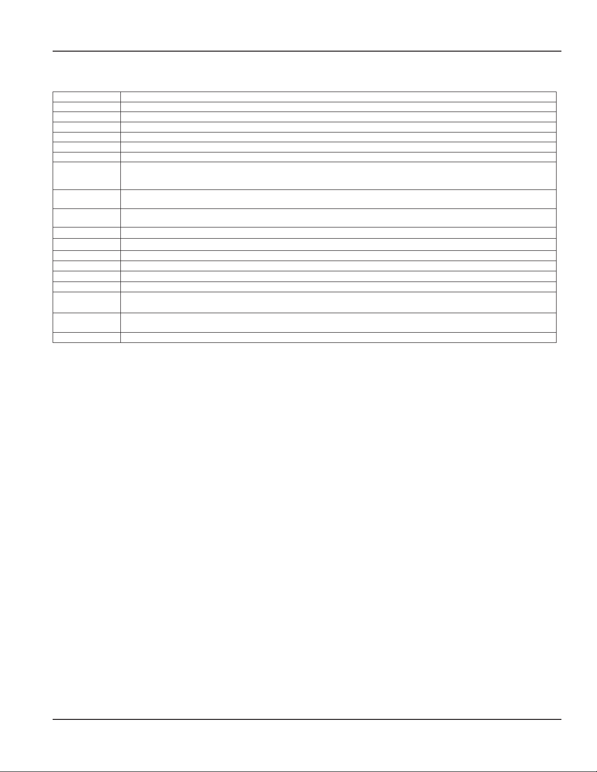
STATUS INDICATORS
Status indicators for the HR-LCD 4-20 scaled/unscaled and pulse registers are described in the table.
Status Indicator Icon Status Description HR LCD Display
Meter functioning
correctly
Register alarm
Reverse flow
Suspected leak
30 day no usage
End of life battery indicator
Register operating
correctly.
Several potential
conditions may exist,
including:
Register removal
Temperature limit
exceeded (34…140° F)
Magnetic tamper
Register detects reverse
flow.
Register detects 24 hours
without one 15-minute
interval of no flow.
No measured flow in past
30 days.
Indicated battery life
based on pre-calculated
consumption.
Continuous display on register as long as no other
status indicators are triggered.
Register alarm remains active for 35 days. The alarm
automatically clears after 35 days if any of the 3
conditions has not recurred.
Reverse flow alarm remains active for 35 days. The
alarm automatically clears after 35 days if reverse flow
condition has not recurred.
The alarm clears automatically when a 15-minute
no-flow interval occurs.
The alarm is automatically cleared once flow occurs.
Alarm activated at 19 years and does not clear.
Control. Manage. Optimize.
Trademarks appearing in this document are the property of their respective entities. Due to continuous research, product improvements and enhancements, Badger Meter reserves
the right to change product or system specications without notice, except to the extent an outstanding contractual obligation exists. © 2018 Badger Meter, Inc. All rights reserved.
www.badgermeter.com
The Americas | Badger Meter | 4545 West Brown Deer Rd | PO Box 245036 | Milwaukee, WI 53224-9536 | 800-876-3837 | 414-355-0400
México | Badger Meter de las Americas, S.A. de C.V. | Pedro Luis Ogazón N°32 | Esq. Angelina N°24 | Colonia Guadalupe Inn | CP 01050 | México, DF | México | +52-55-5662-0882
Europe, Eastern Europe Branch Oce (for Poland, Latvia, Lithuania, Estonia, Ukraine, Belarus) | Badger Meter Europe | ul. Korfantego 6 | 44-193 Knurów | Poland | +48-32-236-8787
Europe, Middle East and Africa | Badger Meter Europa GmbH | Nurtinger Str 76 | 72639 Neuen | Germany | +49-7025-9208-0
Europe, Middle East Branch Oce | Badger Meter Europe | PO Box 341442 | Dubai Silicon Oasis, Head Quarter Building, Wing C, Oce #C209 | Dubai / UAE | +971-4-371 2503
Slovakia | Badger Meter Slovakia s.r.o. | Racianska 109/B | 831 02 Bratislava, Slovakia | +421-2-44 63 83 01
Asia Pacic | Badger Meter | 80 Marine Parade Rd | 21-06 Parkway Parade | Singapore 449269 | +65-63464836
China | Badger Meter | 7-1202 | 99 Hangzhong Road | Minhang District | Shanghai | China 201101 | +86-21-5763 5412
Switzerland | Badger Meter Swiss AG | Mittelholzerstrasse 8 | 3006 Bern | Switzerland | +41-31-932 01 11
 Loading...