

Page 1
GALAXY® Programmer
Handheld Programming Software for TR3 and TR2 Endpoints
GXY-IOM-08-EN (February 2013)
64764-011 Rev. 2 Programming Manual
Page 2

GALAXY® Programmer – Handheld Programming Software for TR3 and TR2 Endpoints
Page ii February 2013
Page 3

Programming Manual
CONTENTS
ABOUT THIS MANUAL . . . . . . . . . . . . . . . . . . . . . . . . . . . . . . . . . . . . . . . . . . . . . . . . . . . . .5
GALAXY PROGRAMMER STARTUP . . . . . . . . . . . . . . . . . . . . . . . . . . . . . . . . . . . . . . . . . . . . .6
TR3 ENDPOINT. . . . . . . . . . . . . . . . . . . . . . . . . . . . . . . . . . . . . . . . . . . . . . . . . . . . . . . . . .8
TR3 Programming Screen. . . . . . . . . . . . . . . . . . . . . . . . . . . . . . . . . . . . . . . . . . . . . . . . .8
Reading the TR3 Endpoint . . . . . . . . . . . . . . . . . . . . . . . . . . . . . . . . . . . . . . . . . . . . . . . .9
Pausing, Stopping and Starting the Radio . . . . . . . . . . . . . . . . . . . . . . . . . . . . . . . . . . . . . 10
Force RF . . . . . . . . . . . . . . . . . . . . . . . . . . . . . . . . . . . . . . . . . . . . . . . . . . . . . . . . . . .11
Read Register . . . . . . . . . . . . . . . . . . . . . . . . . . . . . . . . . . . . . . . . . . . . . . . . . . . . . . .12
Clearing a Tamper . . . . . . . . . . . . . . . . . . . . . . . . . . . . . . . . . . . . . . . . . . . . . . . . . . . . 13
Encoder Tamper Repair . . . . . . . . . . . . . . . . . . . . . . . . . . . . . . . . . . . . . . . . . . . . . . . . . 13
RTR Tamper Repair . . . . . . . . . . . . . . . . . . . . . . . . . . . . . . . . . . . . . . . . . . . . . . . . . . . . 13
Programming a TR3 Endpoint - RTR only . . . . . . . . . . . . . . . . . . . . . . . . . . . . . . . . . . . . . . 14
TR2 ENDPOINT. . . . . . . . . . . . . . . . . . . . . . . . . . . . . . . . . . . . . . . . . . . . . . . . . . . . . . . . .15
TR2 Programming Screen. . . . . . . . . . . . . . . . . . . . . . . . . . . . . . . . . . . . . . . . . . . . . . . .15
Reading the TR2 Endpoint . . . . . . . . . . . . . . . . . . . . . . . . . . . . . . . . . . . . . . . . . . . . . . . 16
Magnet Swipe . . . . . . . . . . . . . . . . . . . . . . . . . . . . . . . . . . . . . . . . . . . . . . . . . . . . . . . 16
Programming the TR2 Endpoint - RTR only . . . . . . . . . . . . . . . . . . . . . . . . . . . . . . . . . . . . .18
SETTINGS . . . . . . . . . . . . . . . . . . . . . . . . . . . . . . . . . . . . . . . . . . . . . . . . . . . . . . . . . . . . 19
ABOUT . . . . . . . . . . . . . . . . . . . . . . . . . . . . . . . . . . . . . . . . . . . . . . . . . . . . . . . . . . . . . . 20
ALERTS . . . . . . . . . . . . . . . . . . . . . . . . . . . . . . . . . . . . . . . . . . . . . . . . . . . . . . . . . . . . . .21
TROUBLESHOOTING . . . . . . . . . . . . . . . . . . . . . . . . . . . . . . . . . . . . . . . . . . . . . . . . . . . . . 22
IR Reading Error . . . . . . . . . . . . . . . . . . . . . . . . . . . . . . . . . . . . . . . . . . . . . . . . . . . . . . 22
IR Programming Bracket . . . . . . . . . . . . . . . . . . . . . . . . . . . . . . . . . . . . . . . . . . . . . . . . 23
TECHNICAL SUPPORT . . . . . . . . . . . . . . . . . . . . . . . . . . . . . . . . . . . . . . . . . . . . . . . . . . . . 24
Page iii February 2013
Page 4

GALAXY® Programmer – Handheld Programming Software for TR3 and TR2 Endpoints
Page iv February 2013
Page 5

Programming Manual
ABOUT THIS MANUAL
The GALAXY® Programmer manual provides instructions for using the GALAXY Programmer software with the Trimble®
Ranger handheld.
Features of the GALAXY Programmer Software
The GALAXY Programmer software is designed for GALAXY TR3 and TR2 endpoints. The endpoints can be used with all
Badger Meter encoders, including the HR-E LCD Encoder, Absolute Digital Encoder (ADE®) and Recordall® Transmitter Register
(RTR®), as well as compatible three-wire competitive encoders. Refer to the GALAXY Fixed Network Water Endpoint Installation
Data manual, GXY-I-10-EN, for details.
Instructions for the following functions of the GALAXY Programmer software are described in this manual:
• Capture meter readings and radio status, including alert flags.
• Start, pause and stop the endpoint radio.
• Verify a repair following a tamper.
• Program the endpoint (RTR only).
Handheld Requirements
The GALAXY Programmer software runs on a Trimble Ranger 3 handheld with a Windows® Mobile 6.5 Professional operating
system and on a Trimble Ranger X handheld with a Windows Mobile 5.0 operating system.
Page 5 February 2013
Page 6
GALAXY® Programmer – Handheld Programming Software for TR3 and TR2 Endpoints
GALAXY PROGRAMMER STARTUP
OTE:N Make sure to securely connect the correct IR cable to the serial port of the handheld before performing any of the
GALAXY Programmer functions. Refer to “IR Reading Error” on page 22 if you need help.
When powered on, the handheld opens to the Windows home screen. Tap the Windows Start button in the lower left corner
of the screen to display the programs on the handheld.
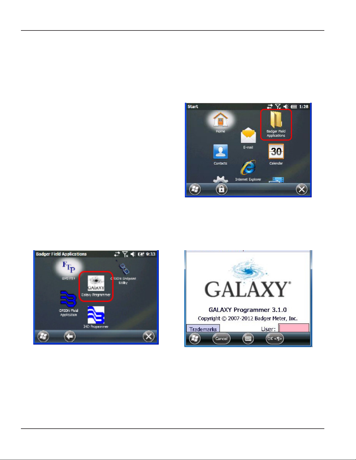
1. Tap the Badger Field Applications folder on the
Windows Start screen.
Result: The suite of Badger Field Applications programs
is displayed as shown in Figure 2.
2. Tap the GALAXY Programmer icon.
Result: The GALAXY login screen opens as shown in Figure 3.
Figure 2: Badger Field Applications
Figure 1: Windows home screen
Figure 3: GALAXY Programmer login screen
Page 6 February 2013
Page 7

3. (Optional) To view the Trademarks, tap the
Trademarks button. To close the Trademarks screen,
tap OK. .
4. On the GALAXY Programmer login screen, tap in the
User eld.
Enter a three to ve character personal identication
number (PIN) using the keypad. The PIN is user
dened. Numbers, letters or a combination of both
are valid.
Result: If your PIN is not valid, an error message is
displayed. Tap OK and re-enter a valid PIN.
When a valid PIN is entered, tap OK or press the ENTER
key on the keypad.
The GALAXY Programmer screen is displayed.
Programming Manual
Figure 4: Trademarks screen
Figure 5: Enter PIN
Page 7 February 2013
Page 8

GALAXY® Programmer – Handheld Programming Software for TR3 and TR2 Endpoints
TR3 ENDPOINT
Figure 6: GALAXY TR3 endpoint
TR3 Programming Screen
The following buttons and fields are included on the TR3 programming screen as shown in Figure 7 on the next page.
Buttons
Program Programs a reading into an RTR endpoint, most commonly after a tamper repair. This button is not
active when reading an ADE or HR-E LCD encoder.
Start Radio Starts the endpoint radio.
Pause Radio Pauses the endpoint radio.
Stop Radio Stops the endpoint radio.
Force RF Forces an endpoint transmission.
Reading Tapping the button activates the Reading field.
Read Reg Reads the register of an ADE or HR-E LCD encoder, most commonly to verify a tamper repair. This
button is not active when reading an RTR endpoint.
Fields
ID/Serial # Endpoint serial number.
Firmware Ver. Endpoint firmware version.
Type Encoder type.
Xmit Intrvl Radio transmission interval in minutes.
Xmit Count Active count of radio transmissions during the life of the endpoint.
OTE:N To perform any of the GALAXY Programmer software functions, remove the cover (PN: 66367-001) of the TR3
endpoint to access the IR port. To remove, squeeze the long sides of the cover at the midpoint and pull.
Page 8 February 2013
Page 9

Reading the TR3 Endpoint
With the TR3 IR tab selected, align the optical read head of
the IR cable with the IR port of the TR3 endpoint and tap the
Read button or press ENTER on the keypad.
OTE:N For best results, the optional TR3 programming
bracket can be used to align the IR cable.
If you need help getting a read, refer to
“IR Reading Error” on page 22.
Two messages display after tapping the Read button.
1. "Please Wait: IR Wakeup in Progress"
2. "Please Wait: IR Read in Progress"
The current read is displayed and the green arrow indicates
the radio is on.
Programming Manual
Figure 7: TR3 reading in progress
Any alerts such as a tamper or leak will also display if they are
reported to the endpoint.
Figure 8: TR3 with read
Page 9 February 2013
Page 10

GALAXY® Programmer – Handheld Programming Software for TR3 and TR2 Endpoints
Pausing, Stopping and Starting the Radio
An initial read must be performed prior to pausing, stopping or starting the radio.
Pausing the Radio
Align the optical read head of the IR cable with the IR port of
the TR3 endpoint and tap the Pause Radio button.
Result: This places the endpoint in a paused state, indicated on
the screen by two yellow vertical bars and the message "Radio
PAUSED."
When a unit of water is registered, the endpoint switches to
"Radio On" mode and the radio will begin transmitting again.
OTE:N The radio can also be manually started using the
Start Radio button.
Stopping the Radio
Figure 9: Radio paused
To ship an endpoint via air, the radio must be stopped.
Align the optical read head of the IR cable with the IR port of
the TR3 endpoint and tap the Stop Radio button.
Result: The radio stops transmitting, indicated on the screen by a
red square and the message "Radio STOPPED."
OTE:N The radio must be manually started using the Start
Radio button if it has been stopped.
Starting the Radio
Start an endpoint if it has been manually stopped or paused.
Align the optical read head of the IR cable with the IR port of
the TR3 endpoint and tap the Start Radio button.
Result: The radio begins to transmit at its programmed interval,
as indicated on the screen by a green arrow and the message
"Radio ON."
Figure 10: Radio stopped
Figure 11: Radio started
OTE:N The TR3 endpoint is shipped in "Radio Paused" mode and will not transmit. When a unit of water is registered, the
endpoint switches to "Radio On" mode. Because of this process, no programming is needed to initially start the
endpoint.
Page 10 February 2013
Page 11

Programming Manual
Force RF
The Force RF command is used to force an endpoint transmission, most commonly to test installation success. An initial read
must be performed prior to forcing a transmission.
1. To force an endpoint transmission, align the optical
read head of the IR cable with the IR port of the TR3
endpoint and tap the Force RF button.
Result: A warning screen is displayed as shown in
Figure 13.
Figure 12: Force RF
2. Tap Yes to continue.
Result: Once a transmission has been sent, the display
returns to the TR3 Programmer screen.
OTE:N Tap No if you want to cancel the
Force RF command.
3. If the Force RF command is unsuccessful, one of two
transmission failed screens is displayed, depending
on whether there is a partial response or no
response from the endpoint.
If either screen is displayed, tap OK to close the
transmission failed screen and repeat steps 1 and
2 until you get a successful transmission. Refer to
“IR Reading Error” on page 22 for additional help.
OTE:N Allow at least 30 seconds between Force RF
commands.
Figure 13: Force RF Warning screen
Figure 14: Transmission failed
Page 11 February 2013
Page 12
GALAXY® Programmer – Handheld Programming Software for TR3 and TR2 Endpoints
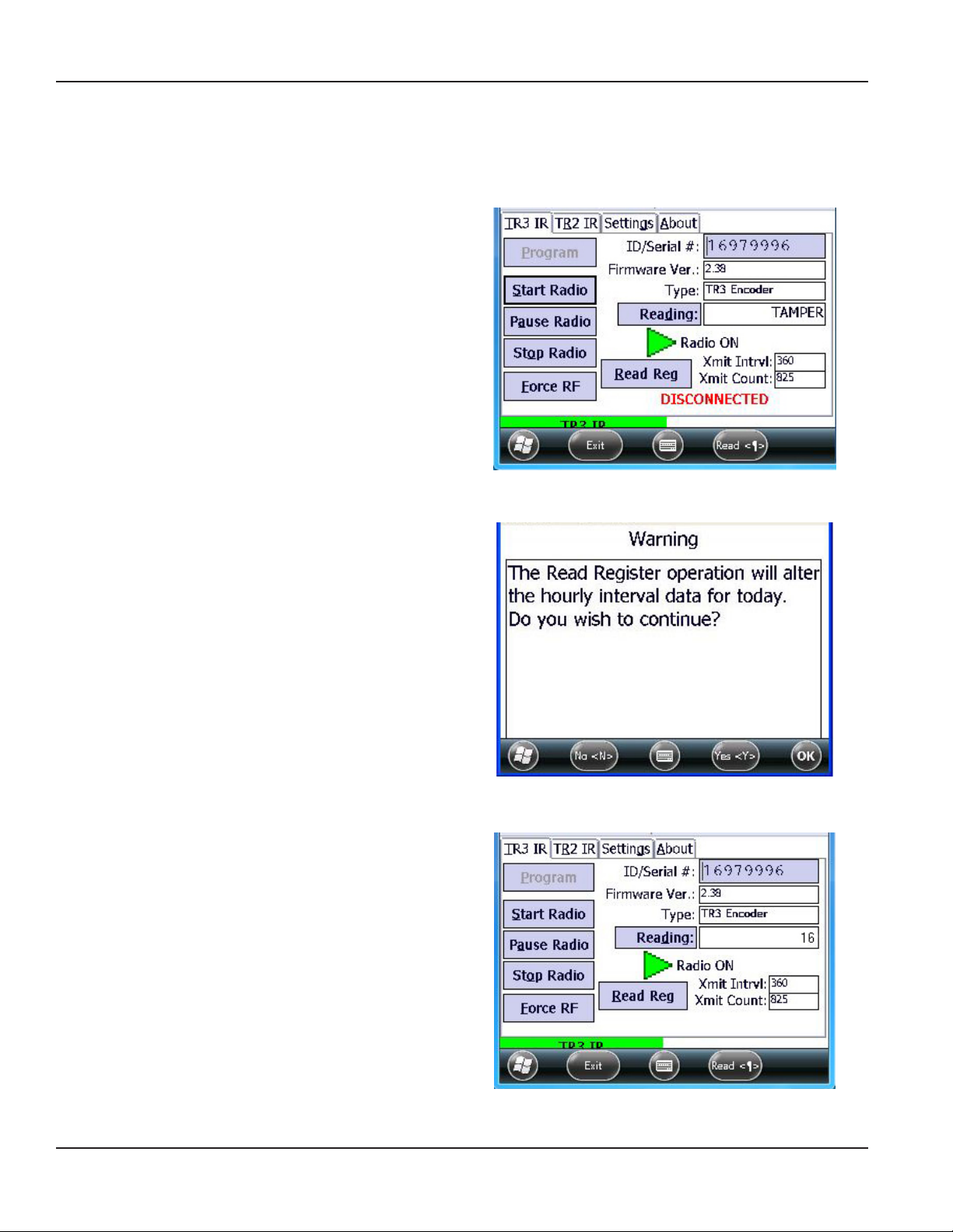
Read Register
The Read Reg button is used to read the register on an encoder, most commonly to verify a tamper repair.
OTE:N The Read Reg button does not display for an RTR.
1. Align the optical read head of the IR cable with the IR
port of the endpoint and tap the Read Reg button.
Result: A screen is displayed warning that reading the
register will change the hourly interval data. See
Figure 16.
Figure 15: Read Register
2. Tap Yes to continue.
OTE:N Tap No if you want to cancel the
read register command.
Result: The current reading from the encoder register is
displayed in the Reading field.
If Read Reg is used to verify a tamper repair, the
reading displays in the Reading field instead of the
word "TAMPER."
If the TAMPER message does not clear, recheck the wire
splice and repeat steps 1 and 2.
IMPORTANT
You must wait 90 seconds between Read Reg
commands to allow endpoint diagnostics to complete.
Figure 16: Read Register Warning screen
Figure 17: Read Register completed
Page 12 February 2013
Page 13

Programming Manual
Clearing a Tamper
When a tamper occurs, the word "TAMPER" displays in the Reading field, and "DISCONNECTED" displays in red at the bottom
of the screen. Follow the steps below to repair and clear a tamper.
Figure 18: Tamper
Encoder Tamper Repair
1. To clear a tamper on an ADE or ELCD endpoint, repair the wire connection from the endpoint to the encoder.
2. Check to see if the repair was successful by using the Read Reg button to read the encoder register. Refer to
“Read Register” on page 12 if you need help.
When the repair is verified, the process is complete. The encoder endpoint is automatically updated to reflect the register
value in the first hour after the wires are repaired.
RTR Tamper Repair
1. To clear a tamper on an RTR endpoint, repair the wire connection from the endpoint to the register.
2. When the wires are successfully reconnected, program the endpoint. Refer to
“Programming a TR3 Endpoint - RTR only” on page 14.
Page 13 February 2013
Page 14

GALAXY® Programmer – Handheld Programming Software for TR3 and TR2 Endpoints
Programming a TR3 Endpoint - RTR only
OTE:N The Program function is for RTR endpoints only. If you try to program an encoder endpoint, the reading you enter
will be replaced by the actual reading.
1. With the TR3 IR tab selected on the programmer screen, align the optical read head of the IR cable with the TR3
endpoint and tap the Read button.
2. Tap Reading to activate the eld.
3. Tap at the end of the current entry in the Reading eld. Then use the DELETE key on the keypad to erase the
current entry.
4. Use the keypad to enter the new reading from the odometer on the encoder register.
5. Align the optical read head of the IR cable with the IR port of the TR3 endpoint and tap Program.
Result: The message "Please Wait: IR Wakeup in Progress" is displayed. When the message disappears, the endpoint is
programmed to start at the reading you entered.
Figure 19: Reading field activated
Figure 20: New read programmed
Page 14 February 2013
Page 15

Programming Manual
TR2 ENDPOINT
Images of GALAXY TR2 endpoints are shown in Figure 21.
Figure 21: GALAXY TR2 endpoints
TR2 Programming Screen
The following buttons and fields are included on the TR2 programming screen as shown in Figure 22 on the next page.
Buttons
Program Programs a reading into an endpoint, most commonly after a tamper repair (RTR only).
Reading Tapping the button activates the Reading field.
Fields
ID/Serial # Endpoint serial number.
Firmware Ver. Endpoint firmware version.
Type Encoder type.
Xmit Intrvl Radio transmission interval in minutes.
Xmit Count Active count of radio transmissions during the life of the endpoint.
Disconnect Count Active count of disconnects during the life of the endpoint.
Leak Count Active count of leaks detected during the life of the endpoint.
OTE:N To perform any of the GALAXY Programmer software functions with the box style TR2 endpoint, remove the cover to
access the IR port.
Page 15 February 2013
Page 16

GALAXY® Programmer – Handheld Programming Software for TR3 and TR2 Endpoints
Reading the TR2 Endpoint
1. On the GALAXY Programmer screen, tap the TR2 IR
tab.
Result: The Cable Select screen is displayed, as shown in
Figure 23, reminding you to attach the IR programming
cable to the handheld if you have not already done so.
2. Tap OK.
Result: The Wakeup GALAXY screen is displayed,
reminding you to swipe the endpoint with a magnet to
put it in communications mode.
3. Tap OK.
Result: The TR2 screen is displayed with the MAGNET
SWIPE message blinking.
Figure 22: TR2 tab
Figure 23: Cable select reminder
Figure 24: Magnet swipe reminder
Magnet Swipe
To put the endpoint in communications mode, hold
the endpoint with the infrared ports in the 12 o'clock
position. Then touch the endpoint with the magnet
at the 3 o'clock position and slowly swipe the long
side of the endpoint as shown. You should feel a
slight pull from the magnet as you swipe.
With a box style endpoint, swipe the magnet along
the side closest to the infrared ports.
The endpoint is ready to be read or programmed.
The MAGNET SWIPE message does not disappear
from the screen until the read is completed.
OTE:N Work quickly. The endpoint stays in
communications mode for only a few
Figure 25: Magnet swipe
seconds after the magnet swipe.
Page 16 February 2013
Page 17

4. Align the optical read head of the IR cable with the
IR port of the TR2 endpoint and tap the Read button
or press ENTER on the keypad.
If you need help getting a read, refer to
“IR Reading Error” on page 22.
"Please Wait: Reading" displays on the screen after
tapping the Read button.
OTE:N The endpoint cannot be read or
programmed until it has been swiped
with the magnet. If the Wakeup GALAXY
screen (Figure 24) displays again, swipe the
endpoint with the magnet, then tap the
Read button again.
The current read is displayed and the endpoint
label displays in green in the lower right corner of
the screen.
Programming Manual
Figure 26: Reading in progress
Figure 27: TR2 with read
Any alerts such as a tamper or leak will also display if they are reported to the endpoint.
Page 17 February 2013
Page 18

GALAXY® Programmer – Handheld Programming Software for TR3 and TR2 Endpoints
Programming the TR2 Endpoint - RTR only
OTE:N Programming is for RTR endpoints only. If you try to program an ADE endpoint, the reading you enter will be
replaced by an actual reading.
1. With the TR2 IR tab selected on the programming
screen, tap the Reading button to activate the eld.
2. Tap at the end of the current entry in the eld. Then
use the DELETE key on the keypad to erase the
current entry.
Figure 28: Reading field activated
3. Use the keypad to enter the new reading from the odometer on the register.
4. Align the optical read head of the IR cable with the IR port of the TR2 endpoint and tap the Program button.
Result: The message "Please Wait: Programming" is displayed.
When the message disappears, the endpoint is programmed to start at the reading you entered.
Figure 29: New reading entered
OTE:N The TR2 endpoint cannot be read or programmed until it has been swiped with the magnet. If the Wakeup GALAXY
screen (Figure 24) displays, swipe the endpoint with the magnet and tap the Program button again.
Figure 30: Programming in progress
Page 18 February 2013
Page 19

Programming Manual
SETTINGS
On the Settings tab, you can view and change the COM port for the IR cable connected to the handheld.
The IR COM port is set to the default of COM1 for both TR2 and TR3 endpoints. To change the default setting, follow these
steps, starting from the GALAXY Programmer screen:
OTE:N Changes to the COM ports should only be made under the direction of Badger Meter Technical Support.
1. Tap the Settings tab to open the IR COM Port screen.
2. Tap the down arrow (∨) or the up arrow (∧) to
change the COM Port for the device listed.
3. Tap Save to accept the new selection.
Tap Cancel to return to the Programmer screen.
Tap Exit to leave the GALAXY Programmer software
and return to the Windows home screen.
Figure 31: COM port settings
OTE:N The Built In and Bluetooth fields are not currently in use. The boxes should remain unchecked.
Page 19 February 2013
Page 20

GALAXY® Programmer – Handheld Programming Software for TR3 and TR2 Endpoints
ABOUT
The About tab displays the software version number and copyright information.
Figure 32: About Tab
Page 20 February 2013
Page 21

Programming Manual
ALERTS
The following alerts, as shown here, will display on the GALAXY Programmer screen when the status is reported to the
endpoint.
• TAMPER
• DISCONNECTED
• ENCODER ERROR
• POTENTIAL LEAK
• Slow Leak
• Fast Leak
• Reverse Flow
Page 21 February 2013
Page 22

GALAXY® Programmer – Handheld Programming Software for TR3 and TR2 Endpoints
TROUBLESHOOTING
IR Reading Error
Figure 33: Reading failure message
If you receive an error message similar to the screen shown here when attempting an IR read, review this checklist to try and
correct the error before attempting to read again.
Use Correct IR Cable
Make sure you are using the correct IR cable. The table below lists the part number of the IR cable to be used with TR3 and TR2
endpoints.
If the endpoint looks like... Use IR cable with part number...
TR3 or TR2 64436-023 OTE:N IR220Lplus is displayed
on the label.
64436-030 OTE:N IR220LN9.6 is displayed
on the label.
TR2
(pit or
original
remote
endpoint)
64976-013 OTE:N Use IR cable
PN: 64976-013 only
with the TR2 endpoints
pictured.
Page 22 February 2013
Page 23

Programming Manual
IR Reading Checklist
After you determine you are using the correct IR cable, review this checklist before attempting to read again.
√ Clean the IR head and the endpoint infrared ports with a soft dry cloth to remove any debris or moisture.
√ Plug the IR cable securely into the handheld serial port.
√ When capturing a read, block as much of the surrounding light as possible.
√ Try another IR programming cable if one is available.
√ Make sure the IR cable is in good condition. Replace it if necessary.
The optional IR Programming Bracket can facilitate an IR read. If you are using the bracket, check the following.
√ Clip the programming bracket securely to the endpoint. See Figure 35.
√ Place the IR head in the slot, facing the correct direction.
√ Make sure the IR head is inserted straight down, into the slot. See Figure 37.
Refer to “IR Programming Bracket” on page 24 for details.
Page 23 February 2013
Page 24

GALAXY® Programmer – Handheld Programming Software for TR3 and TR2 Endpoints
IR Programming Bracket
An optional IR Programming Bracket (PN: 66632-001) can be used to assist in reading GALAXY endpoints. The bracket
facilitates correct alignment between the IR optical read head of the programming cable and the IR port on the endpoint.
The IR programming bracket for GALAXY endpoints has two slots that fit the IR programming cables. The cable serial numbers
are imprinted on the bracket as shown in Figure 34. The slot has two half circle cut-outs to accommodate the small raised
circles on the label side of the IR head. See Figures 36 and 37.
The bracket clips on the endpoint when the cover (PN: 66367-001) is removed. When the bracket is clipped securely to the
endpoint, it clicks into place and lays flat as shown in Figure 35.
Figure 35: Bracket securely clipped to the endpoint (side view)
Figure 34: IR programming bracket (top view)
The images below show the IR head in the slot on the bracket. Figure 36 shows the IR head incorrectly inserted on an angle.
Figure 37 shows the IR head correctly inserted straight down into the slot.
Figure 36: Incorrect placement – arrow shows raised circle on
IR head
Page 24 February 2013
Figure 37: Correct placement
Page 25

Programming Manual
TECHNICAL SUPPORT
For questions or for more information about the GALAXY programming software, contact Badger Meter Technical Support by
phone, email or fax.
Phone: 800-456-5023
Email: TechSupport@BadgerMeter.com
Fax: 888-371-5982
Page 25 February 2013
Page 26

GALAXY® Programmer – Handheld Programming Software for TR3 and TR2 Endpoints
INTENTIONAL BLANK PAGE
Page 26 February 2013
Page 27

INTENTIONAL BLANK PAGE
Programming Manual
Page 27 February 2013
Page 28

ADE, GALAXY and RTR are registered trademarks of Badger Meter, Inc. Other trademarks appearing in this document are the property of their respective entities.
Due to continuous research, product improvements and enhancements, Badger Meter reserves the right to change product or system specications without notice, except to the extent an outstanding
contractual obligation exists. © 2013 Badger Meter, Inc. All rights reserved.
www.badgermeter.com
The Americas | Badger Meter | 4545 West Brown Deer Rd | PO Box 245036 | Milwaukee, WI 53224-9536 | 800-876-3837 | 414-355-0400
México | Badger Meter de las Americas, S.A. de C.V. | Pedro Luis Ogazón N°32 | Esq. Angelina N°24 | Colonia Guadalupe Inn | CP 01050 | México, DF | México | +52-55-5662-0882
Europe, Middle East and Africa | Badger Meter Europa GmbH | Nurtinger Str 76 | 72639 Neuffen | Germany | +49-7025-9208-0
Czech Republic | Badger Meter Czech Republic s.r.o. | Maříkova 2082/26 | 621 00 Brno, Czech Republic | +420-5-41420411
Slovakia | Badger Meter Slovakia s.r.o. | Racianska 109/B | 831 02 Bratislava, Slovakia | +421-2-44 63 83 01
Asia Pacific | Badger Meter | 80 Marine Parade Rd | 21-04 Parkway Parade | Singapore 449269 | +65-63464836
China | Badger Meter | Rm 501, N° 11 Longyue Apartment | N° 180 Longjin Rd, Jiuting Songjiang District | Shanghai, China | 201615 | +86-21-5763 5412
 Loading...