

Page 1
Fluid Management System
Model FMS-3, 2.4 GHz Standalone Keypad
FMS-UM-01811-EN-02 (March 2016)
User Manual
Page 2

Fluid Management System, FMS-3 Standalone Keypad
Page ii March 2016FMS-UM-01811-EN-02
Page 3

User Manual
CONTENTS
Standalone Keypad Description . . . . . . . . . . . . . . . . . . . . . . . . . . . . . . . . . . . . . . . . . . . . . . . . . . . . . . . . . . . . 5
Disclaimer . . . . . . . . . . . . . . . . . . . . . . . . . . . . . . . . . . . . . . . . . . . . . . . . . . . . . . . . . . . . . . . . . . . . . . . .5
Product Identication Information. . . . . . . . . . . . . . . . . . . . . . . . . . . . . . . . . . . . . . . . . . . . . . . . . . . . . . . . .5
Keypad Installation . . . . . . . . . . . . . . . . . . . . . . . . . . . . . . . . . . . . . . . . . . . . . . . . . . . . . . . . . . . . . . . . . .5
Specications . . . . . . . . . . . . . . . . . . . . . . . . . . . . . . . . . . . . . . . . . . . . . . . . . . . . . . . . . . . . . . . . . . . . . . 6
Certication . . . . . . . . . . . . . . . . . . . . . . . . . . . . . . . . . . . . . . . . . . . . . . . . . . . . . . . . . . . . . . . . . . . . . . . 6
Standalone Keypad Keys . . . . . . . . . . . . . . . . . . . . . . . . . . . . . . . . . . . . . . . . . . . . . . . . . . . . . . . . . . . . . . .8
Standalone Keypad Screen Types . . . . . . . . . . . . . . . . . . . . . . . . . . . . . . . . . . . . . . . . . . . . . . . . . . . . . . . . . . . 9
Default Screens. . . . . . . . . . . . . . . . . . . . . . . . . . . . . . . . . . . . . . . . . . . . . . . . . . . . . . . . . . . . . . . . . . . . .9
System Version. . . . . . . . . . . . . . . . . . . . . . . . . . . . . . . . . . . . . . . . . . . . . . . . . . . . . . . . . . . . . . . . . . 9
Enter PIN Number. . . . . . . . . . . . . . . . . . . . . . . . . . . . . . . . . . . . . . . . . . . . . . . . . . . . . . . . . . . . . . . . 9
Management Screens. . . . . . . . . . . . . . . . . . . . . . . . . . . . . . . . . . . . . . . . . . . . . . . . . . . . . . . . . . . . . . . . .9
Multiple-Choice Screens . . . . . . . . . . . . . . . . . . . . . . . . . . . . . . . . . . . . . . . . . . . . . . . . . . . . . . . . . . . . . . 10
Input Screens . . . . . . . . . . . . . . . . . . . . . . . . . . . . . . . . . . . . . . . . . . . . . . . . . . . . . . . . . . . . . . . . . . . . . 10
Initialization (INI) Menu . . . . . . . . . . . . . . . . . . . . . . . . . . . . . . . . . . . . . . . . . . . . . . . . . . . . . . . . . . . . . . . . .11
Time and Date Screens . . . . . . . . . . . . . . . . . . . . . . . . . . . . . . . . . . . . . . . . . . . . . . . . . . . . . . . . . . . . . . . 11
Tank Initialization . . . . . . . . . . . . . . . . . . . . . . . . . . . . . . . . . . . . . . . . . . . . . . . . . . . . . . . . . . . . . . . . . . 11
Fluid Initialization . . . . . . . . . . . . . . . . . . . . . . . . . . . . . . . . . . . . . . . . . . . . . . . . . . . . . . . . . . . . . . . . . . 12
Tank-Fluid Relationship . . . . . . . . . . . . . . . . . . . . . . . . . . . . . . . . . . . . . . . . . . . . . . . . . . . . . . . . . . . .12
Creating or Deleting an RF Meter/Hose (Meter and Hose are Synonymous). . . . . . . . . . . . . . . . . . . . . . . . . . . . . .13
Creating an RF Meter/Hose . . . . . . . . . . . . . . . . . . . . . . . . . . . . . . . . . . . . . . . . . . . . . . . . . . . . . . . . . .13
Deleting an RF Meter/Hose . . . . . . . . . . . . . . . . . . . . . . . . . . . . . . . . . . . . . . . . . . . . . . . . . . . . . . . . . .14
Adding and Deleting Operators . . . . . . . . . . . . . . . . . . . . . . . . . . . . . . . . . . . . . . . . . . . . . . . . . . . . . . . . . 14
Adding an Operator . . . . . . . . . . . . . . . . . . . . . . . . . . . . . . . . . . . . . . . . . . . . . . . . . . . . . . . . . . . . . .14
Deleting an Operator. . . . . . . . . . . . . . . . . . . . . . . . . . . . . . . . . . . . . . . . . . . . . . . . . . . . . . . . . . . . . .14
Conguration (CNF) Menu . . . . . . . . . . . . . . . . . . . . . . . . . . . . . . . . . . . . . . . . . . . . . . . . . . . . . . . . . . . . . . .15
Clearing Transactions from Keypad Memory . . . . . . . . . . . . . . . . . . . . . . . . . . . . . . . . . . . . . . . . . . . . . . . . . 16
System Reset . . . . . . . . . . . . . . . . . . . . . . . . . . . . . . . . . . . . . . . . . . . . . . . . . . . . . . . . . . . . . . . . . . . . . 16
Mileage Type . . . . . . . . . . . . . . . . . . . . . . . . . . . . . . . . . . . . . . . . . . . . . . . . . . . . . . . . . . . . . . . . . . . . . 16
Mileage Information. . . . . . . . . . . . . . . . . . . . . . . . . . . . . . . . . . . . . . . . . . . . . . . . . . . . . . . . . . . . . . . . .16
Registration Information . . . . . . . . . . . . . . . . . . . . . . . . . . . . . . . . . . . . . . . . . . . . . . . . . . . . . . . . . . . . . . 17
Keypad Timeout . . . . . . . . . . . . . . . . . . . . . . . . . . . . . . . . . . . . . . . . . . . . . . . . . . . . . . . . . . . . . . . . . . . 17
Topo Timer . . . . . . . . . . . . . . . . . . . . . . . . . . . . . . . . . . . . . . . . . . . . . . . . . . . . . . . . . . . . . . . . . . . . . .17
Internal Printer . . . . . . . . . . . . . . . . . . . . . . . . . . . . . . . . . . . . . . . . . . . . . . . . . . . . . . . . . . . . . . . . . . . . 17
Page iii March 2016 FMS-UM-01811-EN-02
Page 4

Fluid Management System, FMS-3 Standalone Keypad
External Printer . . . . . . . . . . . . . . . . . . . . . . . . . . . . . . . . . . . . . . . . . . . . . . . . . . . . . . . . . . . . . . . . . . . . 17
Barcode Scanner . . . . . . . . . . . . . . . . . . . . . . . . . . . . . . . . . . . . . . . . . . . . . . . . . . . . . . . . . . . . . . . . . . . 18
Hardware Requirements. . . . . . . . . . . . . . . . . . . . . . . . . . . . . . . . . . . . . . . . . . . . . . . . . . . . . . . . . . . .18
Scanner Lock . . . . . . . . . . . . . . . . . . . . . . . . . . . . . . . . . . . . . . . . . . . . . . . . . . . . . . . . . . . . . . . . . . .18
Pin Number Prex Code . . . . . . . . . . . . . . . . . . . . . . . . . . . . . . . . . . . . . . . . . . . . . . . . . . . . . . . . . . . . 19
New Supervisor Password . . . . . . . . . . . . . . . . . . . . . . . . . . . . . . . . . . . . . . . . . . . . . . . . . . . . . . . . . . . . . 19
Buzzer. . . . . . . . . . . . . . . . . . . . . . . . . . . . . . . . . . . . . . . . . . . . . . . . . . . . . . . . . . . . . . . . . . . . . . . . . .19
Work Order . . . . . . . . . . . . . . . . . . . . . . . . . . . . . . . . . . . . . . . . . . . . . . . . . . . . . . . . . . . . . . . . . . . . . . 19
Display Fluid. . . . . . . . . . . . . . . . . . . . . . . . . . . . . . . . . . . . . . . . . . . . . . . . . . . . . . . . . . . . . . . . . . . . . .20
Meter Reset (MET) Menu . . . . . . . . . . . . . . . . . . . . . . . . . . . . . . . . . . . . . . . . . . . . . . . . . . . . . . . . . . . . . . . . 20
Reports . . . . . . . . . . . . . . . . . . . . . . . . . . . . . . . . . . . . . . . . . . . . . . . . . . . . . . . . . . . . . . . . . . . . . . . . . . . 21
190 Menu (Internal Printer) . . . . . . . . . . . . . . . . . . . . . . . . . . . . . . . . . . . . . . . . . . . . . . . . . . . . . . . . . . . . 21
Report (REP) Menu (External Printer) . . . . . . . . . . . . . . . . . . . . . . . . . . . . . . . . . . . . . . . . . . . . . . . . . . . . . . 21
Initialization Report. . . . . . . . . . . . . . . . . . . . . . . . . . . . . . . . . . . . . . . . . . . . . . . . . . . . . . . . . . . . . . .21
Conguration Report . . . . . . . . . . . . . . . . . . . . . . . . . . . . . . . . . . . . . . . . . . . . . . . . . . . . . . . . . . . . .22
Communications Report . . . . . . . . . . . . . . . . . . . . . . . . . . . . . . . . . . . . . . . . . . . . . . . . . . . . . . . . . . .22
Completed Work Order Report . . . . . . . . . . . . . . . . . . . . . . . . . . . . . . . . . . . . . . . . . . . . . . . . . . . . . . .22
Radio (RAD) Menu . . . . . . . . . . . . . . . . . . . . . . . . . . . . . . . . . . . . . . . . . . . . . . . . . . . . . . . . . . . . . . . . . . . . 23
Radio Address/Radio Prex . . . . . . . . . . . . . . . . . . . . . . . . . . . . . . . . . . . . . . . . . . . . . . . . . . . . . . . . . . . . 23
Radio Network . . . . . . . . . . . . . . . . . . . . . . . . . . . . . . . . . . . . . . . . . . . . . . . . . . . . . . . . . . . . . . . . . . . . 23
Radio Power . . . . . . . . . . . . . . . . . . . . . . . . . . . . . . . . . . . . . . . . . . . . . . . . . . . . . . . . . . . . . . . . . . . . . .24
Radio Status . . . . . . . . . . . . . . . . . . . . . . . . . . . . . . . . . . . . . . . . . . . . . . . . . . . . . . . . . . . . . . . . . . . . . .24
Fluid / Tank Denitions . . . . . . . . . . . . . . . . . . . . . . . . . . . . . . . . . . . . . . . . . . . . . . . . . . . . . . . . . . . . . . . . . 25
Hose / Meter Denitions . . . . . . . . . . . . . . . . . . . . . . . . . . . . . . . . . . . . . . . . . . . . . . . . . . . . . . . . . . . . . . . . 26
Appendix A – Epson LX-300+II Printer or Compatible . . . . . . . . . . . . . . . . . . . . . . . . . . . . . . . . . . . . . . . . . . . . . .27
LX-300+II Printer Settings . . . . . . . . . . . . . . . . . . . . . . . . . . . . . . . . . . . . . . . . . . . . . . . . . . . . . . . . . . . . . 28
Changing LX-300+II Settings . . . . . . . . . . . . . . . . . . . . . . . . . . . . . . . . . . . . . . . . . . . . . . . . . . . . . . . . . . . 32
Page iv March 2016FMS-UM-01811-EN-02
Page 5
Standalone Keypad Description
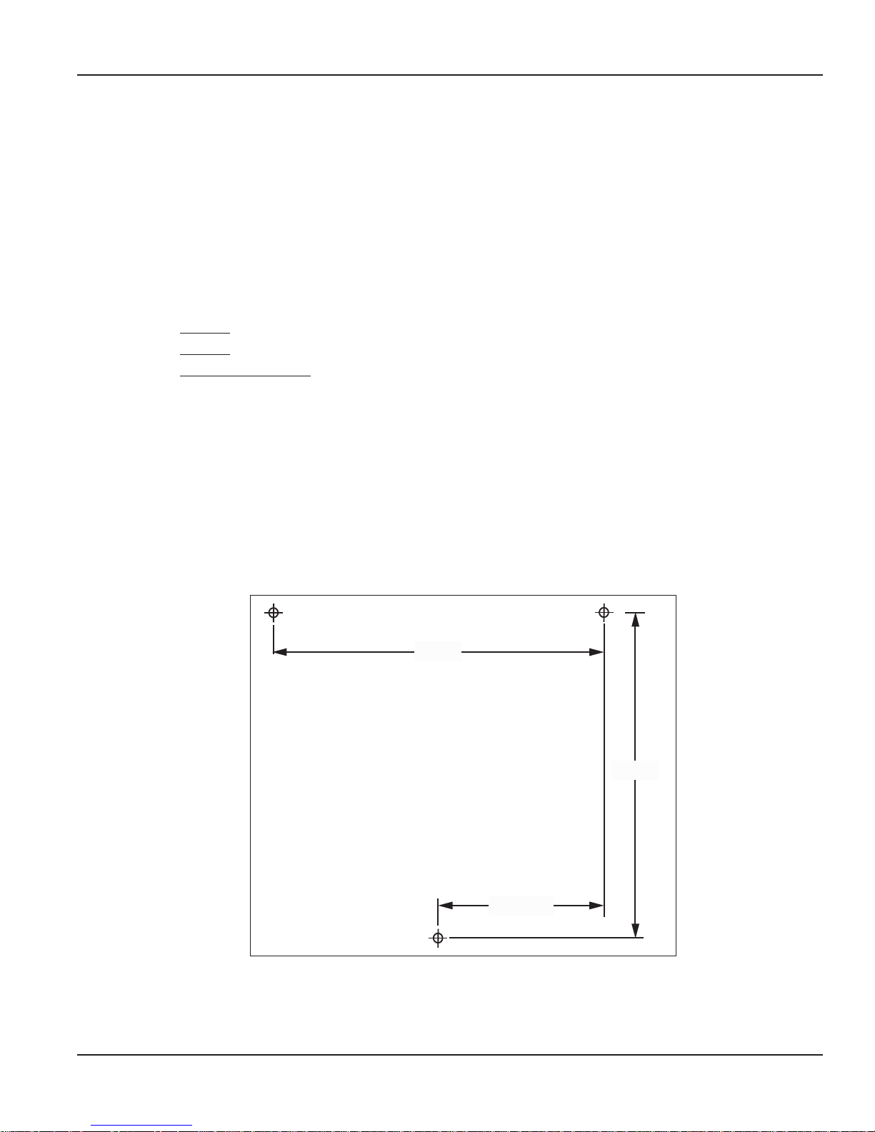
Mounting Dimensions for Keypad
(Holes on Keypad are Threaded for M6 x 1 Screw)
7-5/8”
3-13/16”
7-3/8”
STANDALONE KEYPAD DESCRIPTION
Disclaimer
The user/purchaser is expected to read and understand the information provided in this manual, follow any listed Safety
Precautions and Instructions and keep this manual with the equipment for future reference.
The information in this manual has been carefully checked and is believed to be entirely reliable and consistent with the
product described. However, no responsibility is assumed for inaccuracies, nor does Badger Meter Inc. assume any liability
arising out of the application and use of the equipment described.
Product Identication Information
Record the product identification numbers from the nameplate here.
Model Number _______
Serial Number _______
Tag Number _______(if applicable)
Keypad Installation
• Mount the keypad upright with the antenna pointing upward, near a 120V AC electrical outlet.
• Mount the keypad to a structurally sound wall through the two holes on the top of the keypad case and one hole on the
bottom of the keypad.
• Height on the wall should be 5 feet to 6 feet.
• Avoid direct, significant, heat sources.
• Do not mount the keypad behind any steel objects (tool storage cabinets or metal chain link fences) that may block the RF
communication signals.
Figure 1: Keypad Installation
Page 5 March 2016 FMS-UM-01811-EN-02
Page 6

Standalone Keypad Description
Specications
Power Requirements 120V AC 50/60 Hz
RF Communications 2-way, 2.4…2.5 GHz Direct Sequence Spread Spectrum
RF Network Self-healing Mesh Network
Operating Temperature 14…140° F (–10…60° C)
Certication
• Contains FCC ID: S4GEM35XB
• Contains IC: 8735A-EM35XB
• FCC CERTIFIED, PART 15, SUB-PART C
• CE0681 EC-R&TTE Certified
This device complies with Part 15 of the FCC Rules. Operation is subject to the following two conditions: (1) this device may
not cause harmful interference, and (2) this device must accept any interference received, including interference that may
cause undesired operation.
TO SATISFY FCC RF EXPOSURE REQUIREMENTS FOR MOBILE TRANSMITTING DEVICES, A SEPARATION DISTANCE
OF 20 CM OR MORE SHOULD BE MAINTAINED BETWEEN THE ANTENNA OF THIS DEVICE AND PERSONS DURING
OPERATION. TO ENSURE COMPLIANCE, OPERATIONS AT CLOSER DISTANCES THAN THIS ARE NOT RECOMMENDED.
Page 6 March 2016FMS-UM-01811-EN-02
Page 7

UP TO 30
RF METERS
PER
KEYPAD
Standalone Keypad Description
KEYPAD
HOSE
1:1 WITH METER
10-W-30
GEAR
10-W-40
OIL
UP TO 8 FLUID TYPES AND 8 TANKS PER KEYPAD
Figure 2: Setup Diagram
TRANS
FLUID
Page 7 March 2016 FMS-UM-01811-EN-02
Page 8

Standalone Keypad Description
Standalone Keypad Keys
The Scroll key selects options on the active display.
The Home key returns the display to the default screen.
The Backspace key deletes one character to the left of the cursor each time it is pressed.
The Enter key completes the current action then displays the next screen.
The Space key adds a blank space to the right of the data just entered.
The Alphanumeric keys enter numbers and alpha characters (letters).
• To enter a number, press and release a key.
• To enter a letter, press and hold the key until the letter you want displays, then release the key.
to
Page 8 March 2016FMS-UM-01811-EN-02
Page 9
Standalone Keypad Screen Types
V3.00 2.4GHz
- - - -
STANDALONE KEYPAD SCREEN TYPES
The remainder of this document shows only the actual display, not the entire keypad.
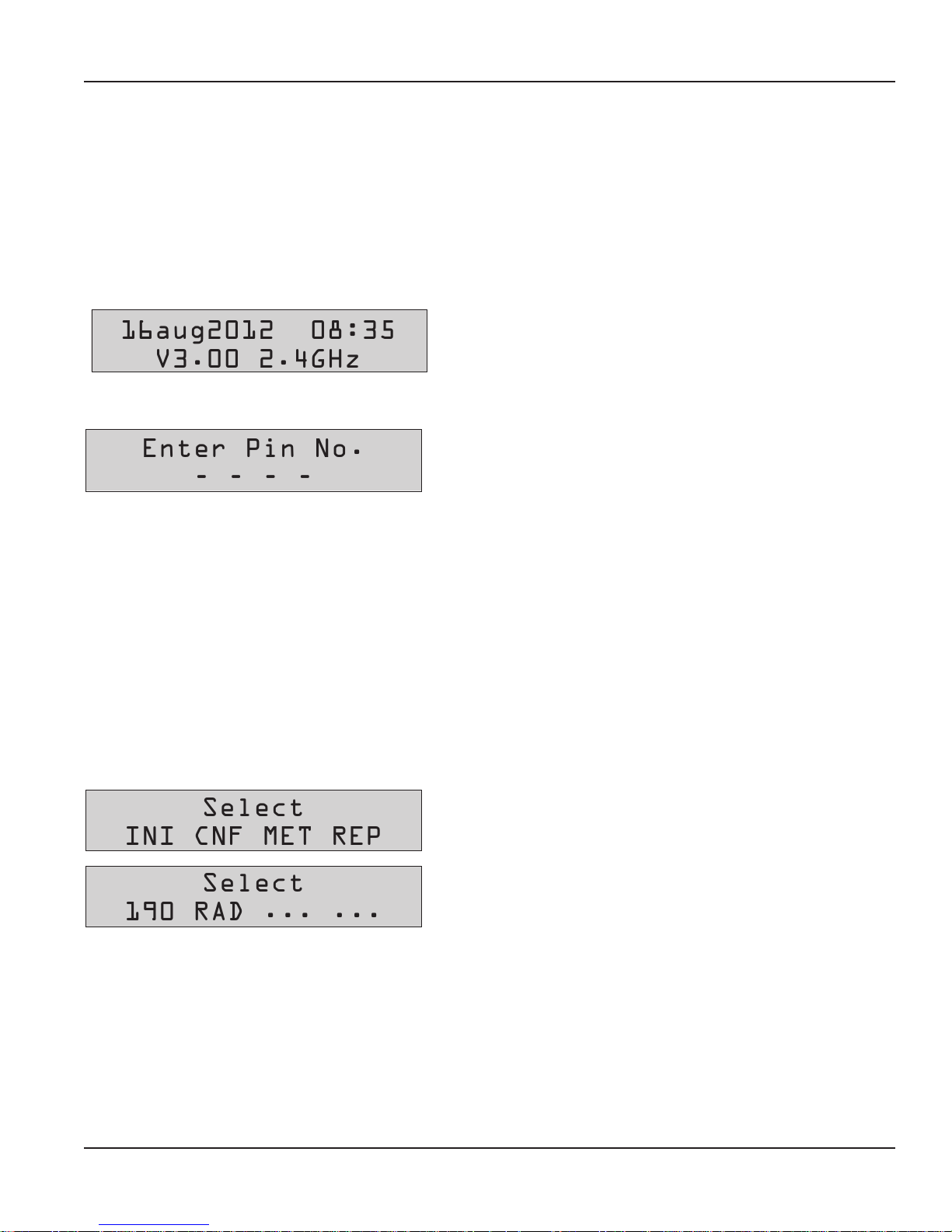
Default Screens
The Default screens toggle between the System Version screen and the Enter PIN Number screen. The System Version screen
displays for 2 seconds, then the Enter PIN Number screen displays for 3 seconds. The cycle repeats until a PIN number
is entered.
System Version
The first default screen is informational. It shows the software version
16aug2012 08:35
Enter PIN Number
Enter Pin No.
Management Screens
number.
The second default screen is used by the supervisor to access the
management screens: Initialization, Configuration, Meter, Report
(External Printer), 190 (Internal Printer) and Radio. There can be only
one supervisor account per keypad.
The Personal Identification Number (PIN) is four digits. To access
management screens, enter the supervisor PIN number. The default is
0000 at initial power-up.
The Management screens are available after the supervisor PIN number has been entered. The Management screens are:
• Initialization (INI)
• Configuration (CNF)
• Meter (MET)
• Report (REP) External Printer
• 190 Report Internal Printer (FT190 is the model number of the internal printer)
• Radio (RAD)
Select
To select a Management screen, press the Scroll key to move through
the menu options until the screen you want is highlighted, then press
Enter.
Select
190 RAD ... ...
Page 9 March 2016 FMS-UM-01811-EN-02
Page 10

Standalone Keypad Screen Types
YES / NO
Tank No =
Multiple-Choice Screens
Mileage Info
Input Screens
Tank Unit
For Multiple-Choice screens, use the Scroll key to move the cursor to
either YES or NO, then press Enter.
To enter or change information on the input screens, press the
Backspace key to delete the current information, then use the keypad
keys to type the new information, then press Enter to save the change.
Page 10 March 2016FMS-UM-01811-EN-02
Page 11

INITIALIZATION INI MENU
--:--
19/aug/2012
The Initialization screens appear in this order:
• Time and Date
• Tank Initialization
• Fluid Initialization
• Adding or Deleting RF Meters/Hoses
• Adding or Deleting Operators
Initialization (INI) Menu
Select
The parameters are:
• System date and time are initially blank
• System time is in military standard
OTE:N System date is in format DD/MMM/YYYY (in English). If you do not want to change the Time and Date settings, press
Enter to advance to the Tank Unit screen.
The INI menu can be accessed only when the Dispense Order (WO)list
is empty. The supervisor must clear all transactions through Configure
(CNF) before the INI menu becomes available. Refer to "Configuration
(CNF) Menu" on page 15 for details on clearing transactions.
Time and Date Screens
To change or set the system time:
Enter time
Enter date
--/jan/----
Enter date
1. Use the numeric keys to set a 24-hour military time of day.
2. Press Enter to save the setting and move to the Enter Date screen.
To change or set the system date:
1. Use the numeric keys to enter the two-digit day.
The cursor automatically moves to the month.
2. Press the Scroll key to select a month.
3. Use the numeric keys to enter the four-digit year.
4. Press Enter to save the setting and advance to the Tank Initialization
screens.
Tank Initialization
The Tank Initialization screens are used to set up tanks in the system. Each tank is assigned a number and a starting quantity
level in the desired unit of measure. The parameters are:
• Maximum of 8 Tanks.
• Tank ID’s are numbered 1 through 8.
• Tank unit of measure can be quarts, liter, pints or gallons.
• Set the dispensing unit of measure to the desired unit.
• The tank stock level setting is updated after each dispense from the associated tank.
• The tank stock level quantity setting format is 5.3 digits (99999.999).
• The remaining tank stock level quantity is printed to the nearest whole number after each dispense on a ticket.
• The Supervisor updates the tank level quantity setting at any time by entering these screens to change stock levels.
Page 11 March 2016 FMS-UM-01811-EN-02
Page 12

Initialization (INI) Menu
Tank No =
Tank No 5
QUARTS
No 5: 85604----
No =
10W40----------
Fluid No =
Tank No 5_
Tank Unit
Tank Unit
Tank Unit No 5
Tank Stock Level
To install a Tank:
1. Select Tank Unit Number.
a. Enter a numeric value from 1 to 8 and press Enter.
b. Pressing the Enter key with no entry advances to Fluids screens.
2. Select Fluid Quantity or Remove a Tank.
a. Use the Scroll key to select LITER, GALLONS, PINTS, QUARTS
or REMOVE.
(The REMOVE option deletes a tank from the system.)
b. Press Enter to advance to the Tank Stock Level screen.
3. Select a Tank Stock Level.
a. Use the numeric keys to enter a stock level from 00000.000 to
99999.999.
b. Press Enter to move to next screen.
c. When all tanks have been added, press Enter to advance to the
Select Fluid screen.
Fluid Initialization
The Field Initialization screen is used to set initial tank stock level or whenever a supplier delivers fluid. The fluid screens allow
a supervisor to set Fluid Names used in the system.
The parameters are:
• Maximum of 8 fluid types
• The fluid type ID number ranges from 1 to 8
• The fluid type name is a 16-character alphanumeric string
• Initially, the fluid type name is blank
Tank-Fluid Relationship
The relationship between tank ID and fluid type ID is 1:1 (one tank assigned to one fluid type). For example, a supervisor may
associate tank #1 with fluid #3 or tank #5 with fluid #5. Each tank must be associated with one, and only one, fluid type.
To associate a tank with a fluid:
Select Fluid
Fluid No. 5
Tank-Fluid
Tank-Fluid
1. Enter a valid number for the uid and press Enter.
2. Enter a name for the uid and press Enter.
3. Enter a valid number for the tank and press Enter.
The Tank-Fluid, Fluid No. screen displays again.
Pressing Enter while the Tank-Fluid, Tank No. screen is blank advances
to the Adding Hoses screen.
Pressing Enter with no entry advances to the Create Hose screen.
4. Enter a valid number for the uid in the tank press Enter.
Pressing Enter after a entering valid tank number displays the
Tank-Fluid, Fluid No. screen again.
Page 12 March 2016FMS-UM-01811-EN-02
Page 13

Initialization (INI) Menu
YES / NO
xx:xx:xx:xx
YES / NO
-.---.---.---
14_
Tank No 5_
Creating or Deleting an RF Meter/Hose (Meter and Hose are Synonymous)
This set of screens allows a supervisor to create or delete RF Meters/Hoses from the keypad.
• The RF Meter/Hose identification number is listed on the RF Meter/Hose under the battery pack or on an attached tag.
Barcode of the Address
Address
• The RF Meter/Hose Address identification number format is 10 decimal digits (X.XXX.XXX.XXX). The Hose Prefix number
format is 8 hexa-decimal (0-9, A-F) digits (XX.XX.XX.XX). Leading zeros must be entered.
• Maximum of 30 RF Meters/Hoses in the system.
• Initially, the RF Meter/Hose address list is empty.
• A keypad can exchange data only with RF Meters/Hoses that have identification numbers entered into the keypad.
• All RF Meter/Hose addresses and IDs are unique.
• The relationship between a tank and RF Meters/Hoses is 1:n (one tank is assigned to n RF Meter/Hoses).
Due to the relationship between tank and fluid type, an RF Meter/Hose is assigned to only one fluid type.
Creating an RF Meter/Hose
• After a valid RF Meter/Hose address is entered, the Tank-Hose screen displays.
• If the RF Meter/Hose address entered is already used, Hose Address Already Used screen displays.
• Pressing the Enter key with no entry moves to the Delete Hose screen
Create Hose
Hose Prefix
Save Prefix?
Hose Address
Hose ID
Tank-Hose
On the Create Hose screen:
1. Use the Scroll key to move the cursor to select YES.
2. Press Enter to advance to the Hose Prex screen.
3. If you need to change the hose prex, press the Backspace key
repeatedly until the cursor is positioned on the rst digit.
4. Type the Hose Prex and press Enter.
1. Use the Scroll key to move the cursor to select YES.
2. Press Enter to save the prex and advance to the Hose Address
screen.
3. Type the Hose Address and press Enter to advance to the Hose ID
screen.
The Hose ID screen identifies which hose is assigned to the tank
and fluid.
OTE:N Hose ID is the number used to create dispense orders for a
meter by an operator.
On the Tank-Hose screen:
4. Enter the number corresponding to the tank and hose and
press Enter.
The relationship between tank and RF Meter/Hose is 1:n (one tank is
assigned to n meters). There is a relationship between tank and fluid
type. The RF Meter/Hose is assigned to one fluid type. Assign the
RF Meter/Hose to the tank to which it is connected.
Page 13 March 2016 FMS-UM-01811-EN-02
Page 14

Initialization (INI) Menu
YES / NO
xx:xx:xx:xx
-.---.---.---
----
----
Hose Address Already Used
Hose Address
Already Used
Deleting an RF Meter/Hose
The supervisor has the option to delete an RF Meter/Hose through this screen. This is necessary when there is a change to the
system or when an RF Meter/Hose needs replacement for any reason.
The supervisor should delete from the keypad the removed RF Meter/Hose prior to creating a new RF Meter/Hose. This puts
the new RF Meter/Hose in the same logical position with the keypad and the dispense order process remaining the same.
This screen displays if another RF Meter/Hose already uses the same
prefix and address. If this screen displays, check the RF Meters in the
system to make sure duplicate RF Meters do not exist. Then check to
see if this RF Meter/Hose has already been created in the system.
The message displays for 3 seconds then returns to Create Hose screen.
Delete Hose
1. Use the Scroll key to move the cursor to select YES.
2. Press Enter to advance to the Hose Prex screen.
3. Type the Hose Prex and press Enter.
Hose Prefix
4. Type the Hose Address and press Enter.
Hose Address
Adding and Deleting Operators
• Only an operator with a valid PIN can dispense fluid.
• A maximum of 49 operators may be active in the system at one time.
• The operator ID (PIN number) format is 4 numeric digits.
• The operator name format is 16 alphanumeric digits. Initially, the operator list is empty.
Adding an Operator
The New Operator screen displays if you press the Enter key when there is no entry.
Pressing the Enter key with no entry displays the New Operator screen.
5. The screen displays the Hose ID of the deleted RF Meter/Hose.
New operator
Deleting an Operator
The Delete Operator screen displays if you press the Enter key when there is no entry.
Delete operator
Page 14 March 2016FMS-UM-01811-EN-02
1. Type in the operator's 4 digit ID PIN number and press Enter to add
it to the list.
2. Type in the operator's name using the keypad and then press Enter
to add it.
3. Repeat steps 1 and 2 to add more operators.
4. When finished adding operators, press Enter while New Operator is
blank.
1. Type in the operator's 4 digit ID PIN number and press Enter to
delete it from the list.
2. Repeat step 1 to delete more operators.
3. When finished deleting operators, press Enter while Delete
Operator is blank.
Page 15

Conguration (CNF) Menu
CONFIGURATION
CONFIGURATION CNF MENU
The Configuration (CNF) Menu allows a supervisor to set up all parameters for the keypad operation. A supervisor is the only
user with access to these screens. When everything is complete in the Configuration Menu, the supervisor should print the
settings from the keypad and put them in a safe place. Refer to "Report (REP) Menu (External Printer)" on page 21 or
"190 Menu (Internal Printer)" on page 21 for information on printing reports.
Select
1. Press the Scroll key until CNF is highlighted.
2. Press Enter.
MENU
Clear Transacts
YES / NO
System Reset
YES / NO
Mileage type
KM / MILES
Keypad Timeout
10
Internal printer
YES / NO
Barcode Scanner
YES / NO
YES
YES
Confirm Reset
YES / NO
Mileage Info
YES / NO
Topoff Timer
300
External Printer
YES / NO
Scanner Lock
PFF PIN ALL
Confirm clear
YES / NO
Regist. Info
YES / NO
Display Timeout
100
New Superv. PW
BUZZER
YES / NO
****
Super Confirm
****
WO Validation
YES / NO
Figure 3: Configuration Menu Flowchart
Display Fluid
YES / NO
Page 15 March 2016 FMS-UM-01811-EN-02
Page 16

Conguration (CNF) Menu
YES / NO
YES / NO
YES / NO
YES / NO
KM / MILES
YES / NO
Clearing Transactions from Keypad Memory
• Removes all transactions (Dispense Orders) previously recorded in memory.
• Clear transactions erases WO results data.
Use the Scroll key to move the cursor to either YES or NO and press
Clear Transacts
Enter.
Print WO?
YES / NO
Confirm Clear
• If you select YES and the external printer is enabled (refer to
"External Printer" on page 17 ), the display asks if you want to print
the WO results.
• If you select YES and the external printer is not enabled, you are
asked to confirm the clear.
• If you select NO, the menu advances to the System Reset screen.
System Reset
The System Reset allows a supervisor to reset all configuration parameters to default values.
1. Use the Scroll key to move the cursor to either YES or NO.
System Reset
Confirm Reset
Mileage Type
The Mileage Type allows a supervisor to select how vehicle mileage is stored in the keypad. The options are KM (default)
and MILES
a. If you select YES, the keypad asks you to Confirm Reset.
b. If you select NO, the keypad advances to the Mileage
Type screen.
2. Press Enter.
Mileage Type
Mileage Information
The Mileage Information screen selects the option to collect vehicle mileage information for each dispense order. The options
are YES and NO (default)
Mileage Info
Page 16 March 2016FMS-UM-01811-EN-02
1. Use the Scroll key to move the cursor to either KM or Miles.
2. Press Enter to advance to the Mileage Info screen.
1. Use the Scroll key to move the cursor to either YES or NO.
2. Press Enter to advance to the Registration Information screen.
Page 17

Conguration (CNF) Menu
YES / NO
10-
0--
YES / NO
YES / NO
Registration Information
The Registration Information screen selects the option to collect registration information for each dispense order. The options
are YES and NO (default).
1. Use the Scroll key to move the cursor to either YES or NO.
Regist. Info
2. Press Enter to advance to the Keypad Timeout screen.
Keypad Timeout
• Timeout parameter corresponds to the time it takes to validate after all dispense order data has been entered. If the Enter
button is not pressed within the time allocated, the keypad display goes back to initial menu and the input data is erased.
• The Keypad Timeout is between zero to 255 seconds (0 = no timeout) and the default for this feature is 10 seconds.
1. Press the Backspace key to erase the current setting.
Keypad timeout
2. Type in the new setting.
3. Press Enter to advance to the Topo Timer screen.
Topo Timer
• This is the time a user has to top-off a dispense after the complete preset batch has been dispensed.
• If a user has not pressed reset on an RF Meter/Hose within the topoff period, the RF Meter/Hose transmits the dispensed
order quantity to the keypad and locks out the RF Meter/Hose.
• The topoff time is equal to one second for each count. For example, 600= 600 seconds or 10 minutes.
• The topoff timer can be set from zero to 15 minutes.
1. Press the Backspace key to erase the current setting.
Topoff Timer
2. Type in the new setting.
3. Press Enter to advance to the Internal Printer screen.
Internal Printer
Use the Internal Printer screen to print dispense ticket information.
Internal Printer
1. Use the Scroll key to move the cursor to either YES or NO.
To print the dispense ticket on the keypad printer, set this option to
YES.
To print to a remote printer or to not print a ticket, set this option
to NO.
2. Press Enter to advance to the External Printer screen.
External Printer
The External Printer (EPSON LX-300) screen is used to print the report information. This must be set to YES to print reports.
1. Use the Scroll key to move the cursor to either YES or NO.
External Printer
2. Press Enter to accept the setting and advance to the next screen.
OTE:N External printer must be set to No to select
the Barcode Scanner.
• If you select YES, the display advances to the New Superv. PW
screen.
• If you select NO, the display advances to the Barcode Scanner
screen.
Page 17 March 2016 FMS-UM-01811-EN-02
Page 18

Conguration (CNF) Menu
YES / NO
OFF PIN ALL
Barcode Scanner
Barcode Scanner
Hardware Requirements
The barcode scanner must support an RS-232 output interface for use in the RF FMS. The barcode scanner serial output must
support standard RS-232 levels of ±3V DC to ±12V DC. Logic level or TTL output signals are not supported by the RF FMS. The
barcode scanner is connected to the RF FMS Dispense Keypad via the external printer RS-232 port with DSUB9 connector
on the bottom of the Standalone Keypad. The RS-232 port on the Standalone Keypad is configured for a Device CircuitTerminating Equipment (DCE) pin out configuration. A null modem adapter is required for barcode scanners that are also
terminated with a DCE pin out configuration. The required RS-232 port settings for the barcode scanner input are as follows:
Hardware Flow Control None
The data output of the barcode scanner is required to be a stream of ASCII characters representing the barcode. To identify the
end of transmission, the stream of ASCII characters should be terminated by a carriage return and line feed ASCII characters.
• Barcode Scanner cannot be used with Remote Printer.
1. Use the Scroll key to move the cursor to either YES or NO.
2. Press Enter to accept the setting and advance to the next screen.
• If you select YES, the display advances to the Scanner Lock screen.
• If you select NO, the display advances to the Scanner screen.
Baud Rate 9600 Baud
Data Bits 8 bits
Stop Bits 1 bit
Parity Odd
• External Printer setting must be set to NO.
Scanner Lock
The Scanner Lock screen has three selectable settings: OFF, PIN, and
Scanner Lock
The table below outlines the screens where the keypad is active or disabled based on the three different settings for the
Scanner Lock feature.
Screen OFF PIN ALL
PIN Entry User Both Scanner Scanner
PIN Entry Supervisor Both Both Both
WO Number Both Both Scanner
Meter ID Both Both Scanner
Quantity Both Both Scanner
AN Field Both Both Scanner
N Field Both Both Scanner
ALL. Depending on the setting chosen, different user input screens will
allow input from the keypad or barcode scanner. .
Page 18 March 2016FMS-UM-01811-EN-02
Page 19

Conguration (CNF) Menu
YES / NO
****
YES / NO
YES / NO
Pin Number Prefix Code
When PIN or ALL is selected for the Scanner Lock, you can choose an additional prefix character. The prefix character will not
be displayed and cannot be entered on the keypad.
1. Use the Scroll key to move the cursor to either YES or NO.
PIN Encoded
Encode Prefix #
2. Press Enter to move to Encode Prex screen.
3. Press the Scroll key until the desired prefix displays. Available
characters are: # $ % & ' ( ) * + , - Space / : ; < = > ? @ [ ] ^ ` { | } ! #
4. Press Enter to advance to the Display Timeout screen..
Display Timeout
100_
The Display Timeout determines how long an entry will remain on the
display before it automatically advances to the next entry screen.
Each count provides a 1/100 of a second delay. A value of 100 is equal
to 1 second.
1. Press the Backspace key to erase the current setting.
2. Type in the new setting.
3. Press Enter to advance to the New Supervisor Password screen.
New Supervisor Password
• The default Supervisor Password is 0000.
• A supervisor can change this password during initial system setup.
• A maximum of one Supervisor login password is allowed.
1. Press the Backspace key to delete the active password.
New Superv. PW
OTE:N If the password is lost, consult the factory for
the procedure to reset it.
2. Use the numeric keys to enter a new password.
3. Press Enter.
(Pressing Enter with no entry just advances to the Buzzer screen
without changing the password.)
4. Re-enter the new password to confirm.
Buzzer
This screen provides a user with the option to have a beep on every key entry. The default is YES.
Buzzer
Work Order
The Work Order screen elects the option to require a work order number to be entered. The options are YES (default) and NO.
WO Validation
1. Use the Scroll key to move the cursor to YES or NO.
2. Press Enter to advance to the Work Order screen.
1. Use the Scroll key to move the cursor to YES or NO.
2. Press Enter to advance to the Display Fluid screen.
Page 19 March 2016 FMS-UM-01811-EN-02
Page 20

Meter Reset (MET) Menu
YES / NO
YES / NO
Press enter
Hose no --
ME
Display Fluid
The Display Fluid screen selects the option to display the fluid selected. The options are YES (default) and NO.
Display Fluid
1. Use the Scroll key to move the cursor to YES or NO.
2. Press Enter to move back to the main Select screen.
METER RESET MET MENU
• Only the supervisor has access to MET.
• The supervisor may delete a dispense order in the keypad queue for a single hose or for all hoses in the system.
• If the supervisor selects all RF Meters, all dispense orders in the queue are deleted.
Select
Init All Hose
Start Hoses Init
1. From the Select menu, use the Scroll key to move the cursor
to MET.
2. Press Enter to advance to the Init All Hose screen.
3. Use the Scroll key to move the cursor to YES and press Enter to
advance to the Start Hoses Init screen.
4. Press Enter to Start Hoses Initiation.
The display then returns to the Select menu.
If you select NO at step 2 above, you will be prompted for a hose number to reset.
1. Type in a hose number.
TER RESET
MENU
Hose Init
Select all?
YES / NO
NO
Hose Init
Hose no - -
YES
2. Press Enter to reset the hose screen.
3. Repeat steps 1 and 2 for all the hoses that require initiation.
4. Press the Home key to return to the Select screen.
Start Hoses Init
Press Enter
Figure 4: Meter Reset Menu Flowchart
Select
INI CNF MET REP
Page 20 March 2016FMS-UM-01811-EN-02
Page 21

Reports
INI CNF COM WO
INI CNF COM WO
REPORTS
When everything is complete in the Configuration Menu, the supervisor should print the settings from the keypad and put
them in a safe place.
You can print reports:
• From an external printer via the Report menu.
• From the internal printer via the 190 menu.
190 Menu (Internal Printer)
The 190 menu screens allow you to print these reports from the internal keypad printer:
• Initialization (INI)
• Configuration (CNF)
• Communication (COM)
• Work Order (WO)
Select
1. Use the Scroll key to move the cursor to the 190 selection.
2. Press Enter to display the Select Report screen.
190 RAD ... ...
3. Use the Scroll key to move the cursor to the report you want to
Select report
print.
4. Press Enter to print the report.
5. Tear o the ticket from the keypad.
6. Press Home to go back to the default screens.
Report (REP) Menu (External Printer)
The supervisor has the opportunity to print out a variety of reports to the External Printer.
• INI prints all parameters associated with the system initialization
• CNF prints all parameters selected for a keypad configuration
• MET prints the status of all hoses/meters
• WO prints the dispense order history
To print reports the External Printer option must be set to YES (see "Configuration (CNF) Menu" on page 15).
Select
Initialization Report
Select report
1. Use the Scroll key to move the cursor to REP.
2. Press Enter to advance to the Select Report screen.
3. Use the Scroll key to select a report.
4. Press Enter to print the report.
1. From the Select Report screen, use the Scroll key to move the cursor
to INI.
2. Press Enter to print the report.
Page 21 March 2016 FMS-UM-01811-EN-02
Page 22

Reports
INI CNF COM WO
INI CNF COM WO
INI CNF COM WO
USR PRO HOS TNK
USR PRO HOS TNK
USR PRO HOS TNK
Configuration Report
Select report
Communications Report
Select report
Completed Work Order Report
Select report
Completed Work Order Reports – Sorted
• USR prints the dispense orders by User.
1. From the Select Report screen, use the Scroll key to move the cursor
to CNF.
2. Press Enter to print the report.
1. From the Select Report screen, use the Scroll key to move the cursor
to COM.
2. Press Enter to print the report.
1. Use the Scroll key to move the cursor to WO.
2. Press Enter to advance to the Select Report screen.
3. Use the Scroll key to select a report.
4. Press Enter to print the report.
• PRO prints the dispense orders by Fluid Type.
• HOS prints the dispense orders by Hose/Meter.
• TNK prints the dispense orders by Tank.
After printing the Work Order List Reports, the Work Order list memory is erased automatically.
User (USR) Report
Stat report
1. Use the Scroll key to move the cursor to INI.
2. Press Enter to print the report.
USR PRO HOS TNK
Fluid Type (PRO) Report
Stat report
Hose/Meter (HOS) Report
Stat report
Tank (TNK) Report
Stat report
1. Use the Scroll key to move the cursor to PRO.
2. Press Enter to print the report.
1. Use the Scroll key to move the cursor to HOS.
2. Press Enter to print the report.
1. Use the Scroll key to move the cursor to TNK.
2. Press Enter to print the report.
Page 22 March 2016FMS-UM-01811-EN-02
Page 23

RADIO RAD MENU
ADR NWK PWR STA
00:0D:6F:00
01:80:A5:63
ADR NWK PWR STA
The RAD menu screens are:
• Address (ADR) – toggles the display between the Radio Address and the Radio Prefix screens.
• Network (NWK) – allows you to select the Radio Network.
• Power (PWR) – displays the radio’s transmit (Tx) output power.
• Station (STA) – displays the Radio Network Status.
Select
To use the internal keypad printer:
1. Use the Scroll key to move the cursor to REP.
Radio (RAD) Menu
Select
190 RAD ... ...
Select
ADR NWK PWR STA
Radio Address/Radio Prex
Once you select ADR, you can use the Scroll key to toggle between the Radio Address and the Radio Prefix screens.
2. Press Scroll two more times to move the cursor to the
RAD selection.
3. Press Enter to display the RAD screen.
4. Use the Scroll key to move the cursor to the information you want
to display.
5. Press Home to go back to the default screens.
1. Use the Scroll key to move the cursor to ADR.
Select
RADIO PREFIX
2. Press Scroll again to display the Radio Prex screen.
3. Press Enter to display the Radio Address screen.
RADIO ADDRESS
4. Press Enter to return to the selection screen.
Radio Network
The Radio Network default is zero. You need to change this setting only if you have multiple RF FMS systems. All
RF Meter/Hose Radio Network settings must match the Standalone Keypad setting.
Select
RADIO NETWORK
0--
1. Use the Scroll key to move the cursor to NWK.
2. Press Enter to display the Radio Network screen.
3. Press Enter to return to the selection screen.
Page 23 March 2016 FMS-UM-01811-EN-02
Page 24

Radio (RAD) Menu
ADR NWK PWR STA
ADR NWK PWR STA
NWK CONNECTED
Radio Power
Select
1. Use the Scroll key to move the cursor to PWR.
2. Press Enter to display the Radio Power Level screen.
3. Press Enter to return to the selection screen.
RADIO PWR LEVEL
20 dBm
Radio Status
The Radio Status options are:
• NWK CONNECTED – The network is connected and operational.
• SERIAL ERROR – There is a radio communication error on the serial bus between the keypad and the radio.
Select
1. Use the Scroll key to move the cursor to STA.
2. Press Enter to display the Radio Status screen.
3. Press Enter to return to the selection screen.
RADIO STATUS
Page 24 March 2016FMS-UM-01811-EN-02
Page 25

Fluid / Tank Denitions
FLUID / TANK DEFINITIONS
• Maximum of 8 Tanks and Fluids.
• The Tank capacity value is formatted xxxxx.xxx.
• Fluid name can be up to 16 alphanumeric characters.
Tank Identification Fluid Identification or Name Tank Level Tank Capacity
1
2
3
4
5
6
7
8
Page 25 March 2016 FMS-UM-01811-EN-02
Page 26

Hose / Meter Denitions
HOSE / METER DEFINITIONS
• Maximum of 30 Hose / Meters.
• Hose Prefix data format is xx.xx.xx.xx (8 digits).
• Hose Address data format is x.xxx.xxx.xxx (10 digits).
Hose / Meter Identification
1
2
3
4
5
6
7
8
9
10
11
12
Hose Prefix
xx.xx.xx.xx
Hose Address
x.xxx.xxx.xxx
Tank Number
13
14
15
16
17
18
19
20
21
22
23
24
Page 26 March 2016FMS-UM-01811-EN-02
Page 27

Appendix A – Epson LX-300+II Printer or Compatible
APPENDIX A EPSON LX300+II PRINTER OR COMPATIBLE
An Epson LX-300+II printer, or compatible, must be used with the Standalone Keypad. Badger Meter takes no responsibility
for, and does not support, any printer except an Epson LX-300+II.
Page 27 March 2016 FMS-UM-01811-EN-02
Page 28

Appendix A – Epson LX-300+II Printer or Compatible
LX-300+II Printer Settings
Page 28 March 2016FMS-UM-01811-EN-02
Page 29

Appendix A – Epson LX-300+II Printer or Compatible
Page 29 March 2016 FMS-UM-01811-EN-02
Page 30

Appendix A – Epson LX-300+II Printer or Compatible
Page 30 March 2016FMS-UM-01811-EN-02
Page 31

Appendix A – Epson LX-300+II Printer or Compatible
Page 31 March 2016 FMS-UM-01811-EN-02
Page 32

Fluid Management System, FMS-3 Standalone Keypad
Changing LX-300+II Settings
1. Go to Google.com.
2. In Google Search, type in LX-300+II.
3. Click on Epson LX-300+II, Overview - Technical Support - Epson America, Inc.
4. On the screen LX-300II Impact Printer, click on Documents & Manuals.
5. On the next screen click on Product information Guide.
6. Go to page 14 (Default Settings).
7. On the right side of the page is a segment titled "Changing Default Settings". Follow the instructions to change settings.
Control. Manage. Optimize.
Trademarks appearing in this document are the property of their respective entities. Due to continuous research, product improvements and enhancements, Badger Meter reserves
the right to change product or system specications without notice, except to the extent an outstanding contractual obligation exists. © 2016 Badger Meter, Inc. All rights reserved.
www.badgermeter.com
The Americas | Badger Meter | 4545 West Brown Deer Rd | PO Box 245036 | Milwaukee, WI 53224-9536 | 800-876-3837 | 414-355-0400
México | Badger Meter de las Americas, S.A. de C.V. | Pedro Luis Ogazón N°32 | Esq. Angelina N°24 | Colonia Guadalupe Inn | CP 01050 | México, DF | México | +52-55-5662-0882
Europe, Middle East and Africa | Badger Meter Europa GmbH | Nurtinger Str 76 | 72639 Neuen | Germany | +49-7025-9208-0
Europe, Middle East Branch Oce | Badger Meter Europe | PO Box 341442 | Dubai Silicon Oasis, Head Quarter Building, Wing C, Oce #C209 | Dubai / UAE | +971-4-371 2503
Czech Republic | Badger Meter Czech Republic s.r.o. | Maříkova 2082/26 | 621 00 Brno, Czech Republic | +420-5-41420411
Slovakia | Badger Meter Slovakia s.r.o. | Racianska 109/B | 831 02 Bratislava, Slovakia | +421-2-44 63 83 01
Asia Pacic | Badger Meter | 80 Marine Parade Rd | 21-06 Parkway Parade | Singapore 449269 | +65-63464836
China | Badger Meter | 7-1202 | 99 Hangzhong Road | Minhang District | Shanghai | China 201101 | +86-21-5763 5412 Legacy Document Number: IOM-208-01-EN PN 53400-208
 Loading...