

Page 1
®
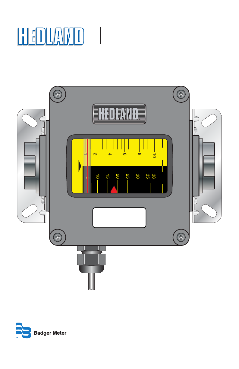
OIL
Flow-Alert
Flow Switch
GPM LPM
FORM #04-VAM-UM-00229 (September 2012)
FLOW-ALERT
FLOW SWITCH
6000 PSI / 414 BARS MAX
Installation & Operation Manual
Page 2

I INTRODUCTION
The Flow-Alert ow meter combines the rugged proven technology of a
direct reading, piston-type, variable area ow meter, coupled with electrical contacts utilized to signal at selected ow rates. This combination is
sealed against industrial contamination by a NEMA 12 and 13 (IP52/54)
rated enclosure.
This product provides a local ow indication and automatically signals the
operator or PLC if ow is too high or too low.
Uses of the Flow-Alert ow meter include: bearing lubrication, case drain
verication, gun drill cooling, pump ow conrmation, etc.
GPM LPM
OIL
FLOW-ALERT
FLOW SWITCH
6000 PSI / 414 BARS MAX
FIGURE 1 FLOWALERT FLOW METER
Page 2 Form #04-VAM-UM-00229 09/12
Page 3

II SPECIFICATIONS
Enclosure Rating
• NEMA 12 & 13
(equivalent to IP52 & 54)
Temperature Range
• -20 °F to +240 °F
(-20 °C to +116 °C)
Pressure Rating Aluminum/Brass
• Liquids (¼” to 1½”): 3500 psi
(241 bar) maximum with a 3:1
safety factor
• Gases (¼” to 1½”): 1000 psi
(69 bar) maximum with a 10:1
safety factor
Pressure Rating Stainless Steel
• Liquids (¼” to ½”): 6000 psi (414
bar) maximum with a 3:1 safety
factor
• Liquids (¾” to 1½”): 5000 psi (345
bar) maximum with a 3:1 safety
factor
• Gases (¼” to 1½”): 1500 psi (103
bar) maximum with a 10:1 safety
factor
Accuracy
• ±2% of full scale
Repeatability
• ±1%
Pressure Drop
• See Appendix for specic meter
information
Micro Switch
• Single (1) or double (2) switch,
pre-wired single-pole, doublethrow (SPDT), UL recognized and
CSA certied switch
• Type: SPDT
• Contact Rating VAC: 250 Volt,
10 Amp
• Contact Rating VDC: 125 Volt,
0.5 Amp
• Cable Single Switch: 34”, 4-wire,
#18 AWG, SO jacket
• Cable Dual Switch: 18”, 7-wire,
#16 AWG, SO jacket
Reed Switch
• Single (1) or double (2) reed
switch, pre-wired single -pole,
single-throw normally open
(SPST-NO); or single-pole,
single -throw normally closed
(SPST-NC); UL recognized and
CSA certied switch
• Type: SPST
• Contact Rating: (maximum, see
Figure 2)
Normally Open, 10 Watts;
Normally Closed, 5 Watts
• Voltage (maximum at switching):
Normally Open, 50 VDC;
Normally Closed, 50 VDC
• Current (maximum amps at
switching, resistive load):
Normally Open, 0.5 Amp;
Normally Closed, 0.5 Amps
• Initial Contact Resistance: 0.100
Ohms
• Cable: 15’ (4.6m), 4-wire, #22
AWG, PVC jacket
Form #04-VAM-UM-00229 09/12 Page 3
Page 4

Safe Operating Area for SPST (NO)
0.6
0.5
0.4
0.3
0.2
(DC Amps)
0.1
Operating Current
0.0
0 4 8 12 16 20 24 28 32 36 40 44 48
Operating Voltage
(VDC)
FIGURE 2 REED SWITCH POWER DISSIPATION
DIMENSIONS
Safe Operating Area for SPST (NC)
0.6
0.5
0.4
0.3
0.2
(DC Amps)
0.1
Operating Current
0.0
0 4 8 12 16 20 24 28 32 36 40 44 48
Operating Voltage
(VDC)
B
A
A
Nominal
Port Size
¼ (SAE 6)
½ (SAE 10)
¾ (SAE 12)
1 (SAE 16)
1¼ (SAE 20) 12.20
1½ (SAE 24) 12.20
B
LengthCLengthDLengthEWidthFWidthGWidthHWidthIDepthJOset
6.60
(168)
6.60
(168)
7.20
(183)
7.20
(183)
(310)
(310)
inches
(mm)
D
C
I
OIL
FLOW-ALERT
FLOW SWITCH
6000 PSI / 414 BARS MAX
K
FIGURE 3 CASE DIMENSIONS
5.27
(134)
5.27
(134)
5.27
(134)
5.27
(134)
10.68
(271)
10.68
(271)
6.41
(163)
6.41
(163)
7.04
(179)
7.04
(179)
11.65
(296)
11.65
(296)
6.00
(152)
6.00
(152)
6.00
(152)
6.00
(152)
7.63
(194)
7.63
(194)
3.23
(82)
3.23
(82)
3.60
(91)
3.60
(91)
4.84
(123)
4.84
(123)
GPM LPM
3.00
(76)
3.00
(76)
3.00
(76)
3.00
(76)
3.82
(97)
3.82
(97)
4.20
(107)
4.20
(107)
4.20
(107)
4.20
(107)
5.02
(128)
5.02
(128)
J
G
F
E
H
K
Hole
Dia.
2.94
(75)
2.94
(75)
2.94
(75)
2.94
(75)
4.50
(114)
4.50
(114)
1.51
(38)
1.51
(38)
1.27
(32)
1.27
(32)
2.20
(56)
2.20
(56)
.31
(8)
.31
(8)
.31
(8)
.31
(8)
.31
(8)
.31
(8)
TABLE 1 DIMENSIONAL INFORMATION
Page 4 Form #04-VAM-UM-00229 09/12
Page 5

III INSTALLATION
CAUTION
Caution - This product should be
installed and serviced by technically qualied personnel trained in
maintaining industrial class ow
instrumentation and processing
equipment.
CAUTION
Caution - Read instructions thoroughly before installing the unit. If
you have any questions regarding
product installation or maintenance, call your local supplier for
more information.
CAUTION
Caution - This meter may contain
residual amounts of test uid at the
time of shipment. This uid should
be removed prior to installation
as the uid may be incompatible
or hazardous with some liquids or
gases. Failure to follow these
WARNING
Warning - Disconnect electrical power before opening wiring
enclosure. Failure to follow these
instructions could result in serious
personal injury or death and/or
damage to the equipment.
WARNING
Warning - All wiring should be
installed in accordance with the
National Electrical Code® and must
conform to any applicable state and
local codes. Failure to follow these
instructions could result in serious
personal injury or death and/or
damage to the equipment.
CAUTION
Caution - Air/gas meters are NOT
oxygen cleaned. Use with oxygen
may cause hazardous or explosive
conditions that may cause serious
personal injury and/or damage to
the equipment.
CAUTION
Caution - This standard meter is
unidirectional. Attempts to ow uids in the opposite direction of the
ow arrow will result in the meter
acting as a check valve, creating a
deadheading situation. If the dierential pressure magnitude is great
enough, damage to the internal
parts of the meter will result.
Form #04-VAM-UM-00229 09/12 Page 5
Page 6

INSTALLATION RECOMMENDATIONS
The in-line ow meter is a simple device to install. However, the following
measures are recommended for reliable, trouble-free operation:
Do - Align pipe accurately. Piping
should be accurately aligned and
of correct length. The high pressure
body of the ow meter can withstand shock and ow/pressure pulsation. However, the piping should
be rmly supported by external
mounting brackets, both upstream
and downstream of the meter, to
avoid any pipe exing actions that
could reduce meter life.
Do - Use rigid mounting. If the ow
meter inlet or outlet are to be rigidly mounted, and the opposing port
is to be connected to exible hose,
the end connected with the exible
hose must be rigidly mounted.
Do - Use Teon® tape for sealing
NPT tting.
Do - Install unions. Install a union
near the inlet or outlet of the meter.
This will facilitate quick, easy meter
removal and inspection during periodic maintenance procedures.
Do - Mount the meter either
horizontally or vertically (ow arrow
pointing to either side or straight
up). If the meter must be mounted
inverted, special inverted scales are
available from the factory.
Do - Use at least a 200 mesh (74
micron) lter. The meter will allow particulate to pass that would
jam most valves and ow controls.
Systems that do not have ltration
should be equipped with at least
a 200 mesh (74 micron) lter. Most
hydraulic systems already have
much ner ltration.
Dirt, ferrous metal or sealing agents,
such as Teon® tape may lodge and
cause malfunction. If the meter is
jammed at a xed position, follow
cleaning and maintenance instructions.
Don’t - Use thread locking compounds as thread sealant.
Don’t - Install the ow meter near
turbulence producing ttings such
as elbows, reducers, close coupled
valves, etc. The in-line ow meter
does not require ow straighteners
or special lengths of straight inlet/
outlet piping to stabilize turbulent
ow patterns. However, to assure
maximum operational reliability,
avoid installation of elbows, valves
and/or reducers immediately adjacent to the meter inlet.
Do - Ensure the uid is traveling
in the direction of the ow arrow
(Figure 4 on page 8).
Page 6 Form #04-VAM-UM-00229 09/12
Page 7

Don’t - Install the meter near fastacting valves. Fast-acting valves
have the potential to create high
magnitude hydraulic pressure
spikes. These spikes can damage
the internal components of the
meter, resulting in inaccuracies or
malfunction.
3. See Figure 6. After installation,
rotate meter by hand to view
ow scale.
ELECTRICAL CONNECTIONS
Micro Switch
Equipped Models
Don’t - Allow unidirectional meters
to be operated against the direction of the ow arrow. The standard
ow meter is an unidirectional ow
meter. The piston acts as a check
valve to block ow in the reverse
direction. This causes an excessive
pressure dierential, which can
All meters (size ¼” to 1½”) are offered in single (1) switch or double
(2) switch models. The single switch
model is equipped with a 34” length
of 4-wire #18 AWG type SO jacketed
cable. The double switch model is
equipped with a 18” length of 7-wire
#16 AWG type SO jacketed cable.
result in damage to internal meter
components. The ow meter is
also available in a modied design,
which oers a reverse ow by-pass
feature to accommodate bi-directional ow.
NOTE: In-line meters with a reverse
ow by-pass feature are available. Consult factory for details.
INSTALLING THE FLOWALERT
1. See Figure 4. Mount the meter
so uid is traveling in the
direction of the ow arrow.
2. See Figure 5. Select a mounting
location that is suitable for
viewing and product service. To
connect the ow meter into the
piping system, place an open-
One Switch 4-Wire Cable
Red Normally Closed (NC)
Black Normally Open (NO)
White Common
Green Ground
Two Switch 7-Wire Cable
Switch 1
Red Normally Closed (NC)
Black Normally Open (NO)
White Common
Switch 2
Orange Normally Closed (NC)
Blue Normally Open (NO)
White/Black Common
Green Ground
TABLE 2 MICRO SWITCH
WIRE DESIGNATIONS
ended wrench onto the ow
meter wrench ats adjacent
to the pipe connection being
installed. DO NOT wrench on
the opposite end of the ow
meter or leakage may result.
Form #04-VAM-UM-00229 09/12 Page 7
Page 8

Flow Direction Arrows
OIL
FIGURE 4 FLOW DIRECTION ARROWS
GPM LPM
OIL
Flow-Al er t
Flow Sw it ch
3500 PSI/241 BARS MAX
GPM LPM
GPM LPM
OIL
Flow-A le rt
Flow S wi tc h
3500 PSI/24 1 BA RS MA X
Place wrench on transmitter ats on the same
side plumbing is being tightened
Place wrench on transmitter ats on the
same side plumbing is being tightened
GPM LPM
OIL
Flow-Al er t
Flow Sw it ch
3500 PSI/241 BARS MAX
GPM LPM
OIL
Flow-A le rt
Flow S wi tc h
3500 PSI/24 1 BA RS MA X
FIGURE 5 INSTALLING THE METER
Never place wrench on transmitter ats
opposite plumbing being tightened
FIGURE 6 ROTATING THE METER
Page 8 Form #04-VAM-UM-00229 09/12
Page 9

A 4-pin Brad Harrison® quickdisconnect plug is available upon
special order.
4-Pin Connector used with
SPDT Micro Switch
Red Normally Closed (NC)
Black Normally Open (NO)
White Common
Green Ground
TABLE 3 4PIN CONNECTOR
MICRO SWITCH
WIRE DESIGNATIONS
NOTE: If the factory supplied cable
is removed for hard wiring the meter,
switches must be connected with
0.187” × 0.020” insulated ag termi-
nals designed for the appropriate wire
gauge for the application.
REED SWITCH MODELS
Safe operation of the reed switch is
dependent on not exceeding the
maximum wattage for that switch.
For example the normally open
reed switch has a maximum power
rating of 10 Watts. If the switch is
to operate at 24 VDC the maximum
current is found by dividing the
wattage by the voltage.
All meters (size ¼” to 1½”) are
oered in single (1) switch or
double (2) switch models and come
equipped with a 4-pin Hirschmann
connector. All units are quipped
with a 15’ length of 4-wire #22 AWG
type PVC jacketed cable.
4-Pin Connector used with
SPST Reed Switch
Red Switch 1 Contact
Black Switch 1 Contact
White Optional Switch 2 Contact
Green Optional Switch 2 Contact
TABLE 4 4PIN CONNECTOR
REED SWITCH
WIRE DESIGNATIONS
ALL MODELS
The strain relief connection on the
outside of the enclosure is watertight. Be sure to consult local wiring
codes before applying power. Some
installations will require rigid conduit. By removing the black strain
relief connections from the outside
of the enclosure, a conduit connection is accessible.
W
I =
Form #04-VAM-UM-00229 09/12 Page 9
10
=
E
= 0.417A
24
Page 10

Wiring Congurations
IV OPERATION
WHITE
Power Line
Load
Load will turn ON when ow exceeds setpoint.
Load
Power Line
Load will turn OFF when ow exceeds setpoint.
BLACK
RED
Flow-Alert
WHITE
Flow-Alert
Power Line
Power Line
FIGURE 7 WIRING CONFIGURATION
FOR LOADS WITHIN
FLOWALERT CONTACT RATINGS
Relay
Coil
R
1
Power Line
Load will turn OFF when ow exceeds setpoint.
Power Line
Load will turn ON when ow exceeds setpoint.
Load
Relay
Coil
Load
R
1
BLACK
BLACK
Flow-Alert
R1
Flow-Alert
R1
WHITE
WHITE
Power Line
Power Line
FIGURE 8 WIRING
CONFIGURATION FOR LOADS THAT
EXCEED FLOWALERT
CONTACT RATINGS
NOTE: Refer to the Appendix for appli-
cation information and uid charts.
MICRO SWITCH ADJUSTMENT
1. Remove cover screws and
front cover.
NOTE: On meters equipped with dual
micro switches, the right-side is the
decreasing ow switch; the left-side is
the increasing ow switch.
2. Loosen the screws securing
the switching roller and
latching rollers to the guide
bar. Turn each screw one full
turn maximum.
3. All rollers are secured as a set
to the spacer strip. Slide the
entire roller set until pointer is
at the desired setting.
NOTE: The spacer strip controls the
maximum distance between rollers.
This distance may be shortened when
the switching setting is close to the end
of the ow scale. Latching rollers may
also be removed if the switching setting is close to the end of the ow scale.
4. Make sure roller brackets are
ush against the guide bar.
Tighten roller screws.
5. For dual switch models,
repeat steps 1-4 for left-side
switch setting.
Page 10 Form #04-VAM-UM-00229 09/12
Page 11

6. Install the cover gasket and
front cover and secure with
screws. To properly seat the
cover gasket, tighten cover
screws in a crisscross pattern
as show in Figure 10.
Latching Roller
Spacer Strip
Switching Roller
Latching Roller
Pointer
Guide Bar
FIGURE 9 SNAP SWITCH
LPM
ADJUSTMENT
4
2
Reed Switch Adjustment for ¼”
Models
1. Loosen the screw securing
the switch assembly (Figure
11).
2. Slide the switch assembly
until the arrow pointers on
the switch band are aligned
with the desired ow rate
indicated on the scale.
3. Tighten the screw.
Reed Switch Adjustment for ¼” to
1½” Models
1. Remove cover screws and front
cover.
2. Loosen the screw securing the
switch assembly (Figure 12).
NOTE: On meters equipped with dual
switches, the right-side is the decreasing ow switch; the left-side is the
increasing ow switch.
GPM LPM
OIL
3. Slide the switch assembly until
the arrow pointer aligns with
the desired ow rate indicated
on the scale.
1
FLOW-ALERT
FLOW SWITCH
6000 PSI / 414 BARS MAX
3
4. Tighten the screw.
5. For dual switch models, repeat
steps 1-4 for left-side setting.
FIGURE 10 COVER SCREW
TIGHTENING SEQUENCE
6. Install the front cover and gasket. To properly seat the cover
gasket, tighten cover screws in
a crisscross pattern as shown in
Figure 10.
Form #04-VAM-UM-00229 09/12 Page 11
Page 12

Arrow Pointers
on Switch Band
GPM LPM
OIL
Screw
V. MAINTENANCE
WARNING
Warning - Disconnect electrical power before removing meter cover. Failure to follow these
instructions could result in serious
personal injury or death and/or
damage to the equipment.
SWITCH REPLACEMENT
Micro Switch (Figure 13)
FIGURE 11 REED SWITCH
ADJUSTMENT ¼” MODELS
GPM LPM
OIL
FIGURE 12 REED SWITCH
ADJUSTMENT FOR
¼” 1½” MODELS
DUAL SWITCH SHOWN
Arrow
Pointer
Screw
1. Disconnect cable connection
to the meter.
2. Remove screws securing cover
and remove cover.
3. Note the positions of the
colored wire connections on
the switch. Disconnect the
wires from the switch.
4. Remove the two mounting
bracket screws at the bottom
of the meter.
5. Remove mounting
bracket/switch assembly
from the meter. Remove the
two screws securing switch to
mounting bracket.
6. Install new switch to mounting
bracket using screws removed
in step 5.
7. Install wires to terminals on
switch as marked in step 3.
8. Install mounting bracket/
switch assembly to meter
using screws removed in step
4.
9. Install the front cover and
Page 12 Form #04-VAM-UM-00229 09/12
Page 13

gasket. To properly seat the
cover gasket, tighten cover
screws in a crisscross pattern
as shown in Figure 10 on page
10.
Reed Switch (Figure 14)
13. Install mounting brackets to
scale using scale mounting
screws. Do not fully tighten
yet.
14. Secure mounting brackets
using screws removed in step
4.
1. Disconnect the Hirschmann
connector and remove
connector from wires.
2. Remove screws securing cover
and remove cover.
3. Remove the two scale
mounting screws.
4. Remove the screws securing
the two mounting brackets
and remove the brackets.
5. Loosen the two slide bracket
screws.
6. Remove the switch mounting
screw and remove mounting
block/switch assembly from
slide bracket.
7. Remove the two mounting
screws securing switch to
mounting block and pointer.
Make note of switch position.
15. Tighten screws installed in
step 10.
16. Solder Hirschmann connector
to new switch wires.
NOTE: For ¼”, ½”, ¾” and 1” units, wire
should be cut to 5” length. For 1¼” and
1½” units, wire should be cut to 10”
length.
17. Install the front cover and
gasket. To properly seat the
cover gasket, tighten cover
screws in a crisscross pattern
as shown in Figure 10.
LPM
Mounting Bracket
Screws (Qty 2)
8. Install new switch to mounting
block and pointer using screws
Snap Switch
Screws (Qty 2)
removed in step 7.
9. Remove the strain relief.
10. Install mounting block/switch
assembly to slide bracket using
screw removed in step 6.
11. Tighten the slide bracket
screws.
12. Install strain relief.
Form #04-VAM-UM-00229 09/12 Page 13
FIGURE 13 MICRO SWITCH
REPLACEMENT
Page 14

Mounting
Mounting
Bracket
Reed
Switch
Scale
Mounting
Screw
GPM LPM
OIL
Bracket
Screws
Side
Bracket
Strain
Relief
Switch
Mounting
Screw
FIGURE 14 REED SWITCH
REPLACEMENT
Cartridge Cleaning (Figure 15)
1. Disconnect the meter cable.
2. Remove the meter from the
line. Remove excess piping
from meter.
WARNING
Warning - Before attempting to
remove the meter from the line,
check the system to conrm that
line pressure has been reduced
to zero PSI. Failure to follow these
instructions could result in serious
personal injury or death and/or
damage to the equipment.
NOTE: It is not necessary to remove the
aluminum housing from the meter to
remove it from the line.
3. Thoroughly wipe o the
entire meter surface using
mild detergent or isopropyl
alcohol.
CAUTION
Caution - Do not use aromatic
hydrocarbons, halogenated hydrocarbons, ketones or ester based
uids on polycarbonate lens. Failure
to follow these instructions could
result in damage to the meter.
4. Remove the inlet end
tting, retaining spring, and
metering cone/spider plate
assembly from the cartridge.
5. Gently push the cartridge
assembly towards the outlet
port while holding magnetic
indicator assembly in place.
6. The cartridge internal parts
are secured with a retaining
ring. Remove the retaining
ring and the remaining
internal parts from the
cartridge.
NOTE: If internal parts do not slide
freely from cartridge, use a wooden
dowel inserted into the outlet port of
the meter to push parts out.
7. Place all parts on a clean work
surface. Clean and inspect all
parts. Replace any that appear
worn or damaged.
8. Check inlet port O-ring
for damage and replace if
required.
Page 14 Form #04-VAM-UM-00229 09/12
Page 15

9. Reassemble spring, then
piston/magnet assembly and
retaining ring into cartridge.
10. Gently push cartridge
assembly into housing while
holding the magnetic ow
indicator in position.
11. Install metering cone/spider
plate assembly, retaining
spring, and secure with inlet
tting.
12. Reinstall meter to the line.
Reconnect electrical power.
[1] - BODY
[2] - CAP
[3] - CONE ASSEMBLY
[1]
[7]
[9]
[3]
[5]
[6]
[4]
[8]
[2]
LPM
FIGURE 15 CARTRIDGE
COMPONENTS
[4] - PISTON
[5] - INNER MAGNET
[6] - INDICATOR MAGNET
[7] - RETAINIGN RING
[8] - WAVE SPRING
[9] - METER SPRING
Quick Re-Coupling
This piston-type variable area ow
meter is inherently less sensitive
to shock and vibration than other
variable area designs. The unique
magnetic coupling also eliminates
the need for mechanical linkages
that can wear or loosen over the
functional life of the meter.
However, on occasion, a pressure
spike or extreme ow surge can
cause the piston to move at such
rapid speed that it disconnects the
piston magnet and the external
indicator ring. If this occurs, use one
of these procedures to re-couple
the magnet and the external indicator ring:
• If the system permits, simply
change ow rate from “no
ow” to “full ow” allowing
the moving piston to
magnetically re-couple to the
indicator ring.
• Remove cover and manually
re-attach external ow
indicator to internal magnet/
piston assembly.
• For rigorous cyclical
applications where decoupling may occur
frequently, consult the
technical services sta for
further recommendations.
Form #04-VAM-UM-00229 09/12 Page 15
Page 16

VI APPENDIX
APPLICATION
INFORMATION PNEUMATIC
APPLICATION
INFORMATION LIQUID
Viscosity Eect (SUS/cSt)
The design utilizes a precision
machined, sharp-edged orice and
biasing calibration spring that assures operating stability and accuracy over the wide viscosity range
common to many uids. Generally,
high ow models of each meter
size provide good accuracy over a
viscosity range of 40 to 500 SUS (4.2
to 109 cSt).
Density Eect
(specic gravity)
Any uid density change from
stated standards has a proportional
eect on meter accuracy. Special
scales can be supplied if actual specic gravity decreases accuracy beyond application limits. Corrections
for more or less dense uids can be
made to standard scales using the
following correction factor:
10.
Specic Gravity
for water/water-based meters
0 876.
Specic Gravity
NOTE: Pressure and temperature readings must be taken at the ow meter
inlet to ensure accurate correction
factors.
The pneumatic ow meter is oered
with a standard graduated dual
scale, calibrated for air in standard
cubic feet per minute (scfm) at 1.0
s.g. (70 °F @ 100 psi), and liter per
second (lps) at 1.0 s.g. (21 °C @ 6.9
bar).
PRESSURE
PRESSURE
SOURCE
GAUGE TEMP
FLOW
METER
AIR BLEED OFF
TO EQUIPMENT
ADJUSTABLE
VALVE
Conversion Chart
The Conversion Chart provides a
series of simplied mathematical
formulas to “correct” the graduated
scale for changes in pressure
(Table 1), temperature (Table 2),
and/or specic gravity (Table 3).
Special scales can be made to accommodate other pressures, temperatures and specic gravity.
The conversion chart can also be
used to “correct” (adjust) the Multipressure Flow Scale to indicate ow
rates in applications beyond the
parameters stated on the scale.
for petroleum-based meters
Page 16 Form #04-VAM-UM-00229 09/12
Page 17

To adjust Pressures beyond
(above or below) scale limits:
Step 1. Locate point at which the
brightly colored indicator line intersects the vertical 100 PSIG pressure
line.
Step 2. Divide this reading by the
Pressure Correction Factor (f1) indicated in the Conversion Chart.
To adjust for changes
in Temperature :
Step 1. Divide the 100 PSIG ow
rate reading by the Temperature
Correction Factor (f2).
To adjust for changes
in Specic Gravity:
Step 1. Establish the square root of
the new specic gravity.
Step 2. Divide the 100 PSIG ow
rate reading by the Specic Gravity
Correction Factor (f3).
Form #04-VAM-UM-00229 09/12 Page 17
Page 18

DETERMINE FLOW RATES USING DIFFERENT PRESSURES & TEMPERATURES
()
13
scfm actual
()
scfm indicated
=
fxfxf
2
Where f1 = Conversion Factor for Inlet Pressure
f2 = Conversion Factor for Inlet Pressure
f3 = Conversion Factor for Inlet Pressure
Table 1 - Pressure Correction Factor (f1) Operating Pressure
psig 25 50 75 100 125 150 175 200 225 250
BAR 1.7 3.5 5.2 6.9 8.6 10.4 12.1 13.8 15.5 17.2
kPa 172 345 517 689 862 1034 1207 1379 1551 1724
f
1.700 1.331 1.131 1.00 .902 .835 .778 .731 .692 .658
1
790 857
7 914
f
114 7
1
14 7=+..
psig
f
1
.
1 014=+
.
BAR
f
1
.
101 357=+
.
kPa
Table 2 - Temperature Correction Factor (f2)
ºF +10 +30 +50 +70 +90 +110 +130 +150 +170 +190
°C -12.2 -1.1 +9.9 +21.0 +32.1 +43 +54 +65 +76 +88
F
.942 .962 .981 1.00 1.018 1.037 1.055 1.072 1.090 1.107
2
C
273
F
460
f
2
+°
=
530
f
2
+°
=
293
Table 3 - Specic Gravity Correction Factor (f3)
fSpGr3 = ..
FIGURE 16 CONVERSION CHART
Page 18 Form #04-VAM-UM-00229 09/12
Page 19

LIQUIDS
Correction
Fluid
Acetic Acid (Air Free) 1.06 0.909 0.971 C N R R R R C N R
Acetone 0.79 1.053 1.125 R R R R N R N R R
Alcohol Butyl (Butanol) 0.83 1.027 1.098 C C R R C R R R R
Alcohol Ethyl (Ethanol) 0.83 1.027 1.098 C C R R C R R N R
Ammonia 0.89 0.992 1.060 R C R R N R N C R
Benzine 0.69 1.127 1.204 C R R C R N N R R
Carbon Disulphide 1.26 0.834 0.891 R N R R R N N R R
Castor Oil 0.97 0.950 1.015 C R R C R N C C R
Cotton Seed Oil 0.93 0.970 1.037 C R R R R N R R R
Ethylene Glycol 50/50 1.12 0.884 0.945 R R R R R R R C R
Freon II 1.46 0.774 0.828 R R R R R N R R R
Gasoline 0.70 1.119 1.195 R R R R R N C R R
Glycerin 1.26 0.834 0.891 R R R R R R R C R
Kerosene 0.82 1.033 1.104 R R R R R N R R R
Liquid Propane (LPG) 0.51 1.310 1.400 R R R R R N N R R
Mineral Oil 0.92 0.976 1.042 R N R R R N R R R
Naphtha 0.76 1.074 1.147 R N R R R N C R R
Perchloroethylene 1.62 0.735 0.786 C N R R R N N N R
Petroleum Oil 0.876 1.000 1.068 R R R R R N R R R
Phosphate Ester 1.18 0.862 0.921 R R R R N R N R R
Phosphate Ester Base 1.26 0.833 0.891 R R R R N R N R R
Phosphoric Acid (AIr Free) 1.78 0.701 0.749 N N R N R N R N R
Sea Water 1.03 0.922 0.985 N N C C N R R R R
Synthetic Petroleum Base 1.00 0.936 1.000 R C R R R N R R R
Water 1.00 0.936 1.000 N R R R N R R R R
Water Glycol 50/50 1.07 0.905 0.967 R R R R R N R R R
Water-in-oil 0.93 0.970 1.037 R R R R N R R R R
R - Recommended N - Not Recommended C - Consult Factory
Specic
Gravity
Factor
Oil Wat er
Brass
Aluminum
T316 SST
T303 SST
Viton®
EPR
Nylon
Polycarbonate
Pyrex®
FIGURE 17 FLUID SELECTION CHART LIQUIDS
Form #04-VAM-UM-00229 09/12 Page 19
Page 20

GASES
Fluid
Air 1.0 1.000 R R R R R R R R R
Argon (A) 1.38 1.175 R R R R R R R R R
Carbon Dioxide (CO2) 1.53 1.237 R R R R R R R R R
Freon 11 (CCI3F) 4.92 2.218 R R R R R R R R R
Freon 12 (CCI2F) 4.26 2.060 R R R R R R R R R
Helium (HE) 0.14 0.374 R R R R R R R R R
Hydrogen (H2) 0.07 0.265 R R R R R R R R R
Natural Gas 0.60 0.775
Specic
Gravity
Correc-
tion
Factor
Brass
Aluminum
T316 SST
T303 SST
Viton®
EPR
Nylon
Polycarbonate
C C R C R N C R R
Nitrogen (N2) 0.97 0.985 C C R R R R C R R
Oxygen (02) 1.10 1.049 R R R R R R R R R
Propane (C3H8) 1.57 1.253 R R R R R N N R R
R - Recommended N - Not Recommended C - Consult Factory
FIGURE 18 FLUID SELECTION CHART GASES
Pyrex®
Page 20 Form #04-VAM-UM-00229 09/12
Page 21

FLOW VS. PRESSURE DROP
1/2" Reverse Flow
0.2-2.0
PRESSURE DROP, PSI
0.1-1.0
PRESSURE DROP, PSI
PRESSURE DROP, PSI
0.5-5.0
FLOW, GPM
1/4"
.02-.20
3/4"/ 1"
1-10
.05-.50
.10-1.0
FLOW, GPM
2-20
FLOW, GPM
1-15
4-40
3-30
10
5
0.2-2.0
0
0 10
PRESSURE DROP, PSI
0.2-2.0
.20-2.0
5-50
1-10
0.5-5.0
3/4"/1" Reverse Flow
2-20
1-10
0.5-5.0
FLOW, GPM
PRESSURE DROP, PSI
PRESSURE DROP, PSI
3-30
1/2"
0.2-2.0
0.1-1.0
1-1/4"/1-1/2"
3-30
4-40
1-10
0.5-5.0
FLOW, GPM
10-100
10-75
5-50
FLOW, GPM
1-1/4"/1-1/2" Reverse Flow
PRESSURE DROP, PSI
3-30
1-15
10-150
10-150
10-100
10-75
5-50
FLOW, GPM
PETROLEUM FLUIDS
Form #04-VAM-UM-00229 09/12 Page 21
Page 22

1/4"
FLOW, GPM
PRESSURE DROP, PSI
FLOW, GPM
FLOW, GPM
0.10-1.0
0.20-2.0
1/2"
1-15
1/2" Reverse Flow
0.2-2.0
0.5-5.0
0.1-1.0
1/4"
.02-.20
6
.05-.50
4
FLOW, GPM
2-20
FLOW, GPM
2
0
3-30
0.50.0
4-40
6
4
2
0
0 1 2 3 54
3/4"/1" Reverse Flow
PRESSURE DROP, PSI
0.2-2.0
0.5-5.0
0.5-5.0
PRESSURE DROP, PSI
5-50
0.2-2.0
1-10
1-1/4" / 1-1/2"
PRESSURE DROP, PSI
3-30
4-40
3-30
2-20
PRESSURE DROP, PSI
3/4"/ 1"
PRESSURE DROP, PSI
1-10
1-15
1-10
0.5-5.0
5-50
FLOW, GPM
10-75
FLOW, GPM
10-100
1-10
PRESSURE DROP, PSI
4
0.1-1.0
2
0
0 1 2 2.5
0.2-2.0
10-150
1-1/4"/1-1/2" Reverse Flow
10-75
5-50
3-30
10-150
10-100
PHOSPHATE ESTER
.10-1.0
.20-2.0
1/2"
1-10
1-15
0.5-5.0
0.2-2.0
PRESSURE DROP, PSI
PRESSURE DROP, PSI
3/4" / 1"
FLOW, GPM
4-40
3-30
2-20
FLOW, GPM
PRESSURE DROP, PSI
FLOW, GPM
1-1/4"/ 1-1/2"
10-75
5-50
3-30
PRESSURE DROP, PSI
FLOW, GPM
A.P.I. OIL
Page 22 Form #04-VAM-UM-00229 09/12
10-100
Page 23

PRESSURE DROP, PSI
1/4"
.10 -1.0
0.2-2.0
.05-.50
.20-2.0
PRESSURE DROP, PSI
1/2"
0.5-5.0
1-15
1-10
0.1-1.0
0.2-2.0
PRESSURE DROP, PSI
3/4" / 1"
5-50
4-40
3-30
2-20
0.5-5.0
0.2-2.0
1-10
PRESSURE DROP, PSI
0.2-2.0
FLOW, GPM
1/2" Reverse Flow
0.5-5.0
0.1-1.0
FLOW, GPM
PRESSURE DROP, PSI
1-10
1-1/4"/ 1-1/2"
5-50
3-30
FLOW, GPM
10-150
10-100
10-75
FLOW, GPM
1-15
3/4"/1" Reverse Flow
PRESSURE DROP, PSI
0.5-5.0
0.2-2.0
2-20
1-10
FLOW, GPM
WATERBASED FLUIDS
PRESSURE DROP, PSI
FLOW, GPM
3"
20-180
20-275
FLOW, GPM
4-40
3-30
1-1/4"/1-1/2" Reverse Flow
PRESSURE DROP, PSI
5-50
3-30
10-100
10-75
10-150
FLOW, GPM
Form #04-VAM-UM-00229 09/12 Page 23
Page 24

1/4"
.10 -1.0
.20-2.0
1/2"
1-15
1-10
PRESSURE DROP, PSI
PRESSURE DROP, PSI
3/4" / 1"
1/4"
FLOW, GPM
3-30
2-20
FLOW, GPM
.10 -1.0
0.2-2.0
4-40
0.5-5.0
.20-2.0
.05-.50
0.2-2.0
5-50
1-10
WATER
PRESSURE DROP, PSI
PRESSURE DROP, PSI
0.5-5.0
1-1/4"/ 1-1/2"
5-50
3-30
1/2"
0.5-5.0
0.1-1.0
0.2-2.0
FLOW, GPM
10-150
10-100
10-75
FLOW, GPM
1-15
1-10
0.2-2.0
PRESSURE DROP, PSI
FLOW, GPM
PRESSURE DROP, PSI
FLOW, GPM
1-1/4"/ 1-1/2"
3/4" / 1"
PRESSURE DROP, PSI
3-30
2-20
FLOW, GPM
4-40
0.5-5.0
0.1-2.0
1-10
PRESSURE DROP, PSI
3-30
10-100
10-75
5-50
FLOW, GPM
CAUSTIC AND CORROSIVE LIQUIDS
Page 24 Form #04-VAM-UM-00229 09/12
Page 25

25
1/4"
20
15
1-10
2-20
10
5
PRESSURE DROP, PSI
0.5-5
0
0 105 15 20 25 30
FLOW, SCFM
3-30
20
1/2"
15
10
5-50
3-25
10-100
5
PRESSURE DROP, PSI
0
0 5025 75 100 125 150
FLOW, SCFM
15-150
20
3/4" / 1"
15
10
3-25
5
10-100
15-150
5-50
PRESSURE DROP, PSI
0
0 10050 150 200 250
FLOW, SCFM
AIR / COMPRESSED GASES
25
1/4"
20
15
10
5
PRESSURE DROP, PSI
0
0 105 15 20 25 30
FLOW, SCFM
20
3/4" / 1"
15
10
3-25
5
10-100
5-50
PRESSURE DROP, PSI
0
0 10050 150 200 250
FLOW, SCFM
2-20
15-150
25-250
3-30
25-250
30
25
1-1/4"/ 1-1/2"
100-1000
20
15
10
5
PRESSURE DROP, PSI
0
0 400200 600 800 1000
40-400
20-200
80-800
60-600
FLOW, SCFM
20
1/2"
15
10
5-50
3-25
10-100
5
PRESSURE DROP, PSI
0
0 5025 75 100 125 150
FLOW, SCFM
30
1-1/4"/ 1-1/2"
25
100-1000
20
15
10
5
PRESSURE DROP, PSI
0
0 400200 600 800 1000
40-400
20-200
80-800
60-600
FLOW, SCFM
15-150
AIR / CAUSTIC AND CORROSIVE GASES
Form #04-VAM-UM-00229 09/12 Page 25
Page 26

NOTES
Page 26 Form #04-VAM-UM-00229 09/12
Page 27

®
Badger Meter Warranty
Flow-Alert Flow Switch
PRODUCTS COVERED
The Badg er Meter warrant y shall apply to th e Hedland Flow-
Alert Flow Switch (“Product”).
MATERIALS AND WORKMANSHIP
Badger M eter warrants th e Product to be fre e from defect s in
material s and workmanshi p for a period of 12 months f rom the
original purchase date.
PRODUCT RETURNS
Produc t failures must be p roven and verifi ed to the satisfa ction
of Badger Meter. The Badger Meter obligation hereunder
shall be li mited to such repair a nd replacement a nd shall be
conditi oned upon Badge r Meter receivi ng written noti ce of any
assert ed defect with in 10 (ten) days after its di scovery. If the
defec t arises and a valid c laim is received wi thin the Warranty
Period, at its option, Badger Meter will either (1) exchange
the Produ ct with a new, used or re furbished Pro duct that is
at least fu nctionally e quivalent to the or iginal Product , or (2)
refund t he purchase price o f the Product. DO N OT RETURN
ANY PRODU CT UNTIL YOU HAVE CALL ED THE BADGER METE R
CUSTOMER SE RVICE DEPARTMENT AND O BTAINED A RE TURN
AUTHORIZATION.
Produc t returns must be sh ipped by the Custom er prepaid F.O.B.
to the near est Badger Mete r factory or dis tribution cente r. The
Customer shall be responsible for all direct and indirect costs
associated with removing the original Product and reinstalling
the repaired or replacement Product. A replacement Product
assumes the remaining warranty of the original Product or
ninet y (90) days from the date of r eplacement, wh ichever
provides longer coverage.
LIMITS OF LIABILITY
This warranty shall not apply to any Product repaired or
altered b y any Product other t han Badger Mete r. The fore going
warrant y applies only to t he extent that th e Product is
install ed, service d and operated st rictly in accorda nce with
Badger Meter instructions. The warranty shall not apply and
shall be vo id with respect t o a Product expos ed to conditions
other than those detailed in applicable technical literature
and Inst allation and Ope ration Manuals (IO Ms) or which have
been subj ect to vandalis m, negligence, ac cident, acts of G od,
improper installation, operation or repair, alteration, or other
circumstances which are beyond the reasonable control of
Badger Meter.
With resp ect to produc ts not manufac tured by Badger Me ter,
the warra nty obligatio ns of Badger Mete r shall in all respec ts
conform a nd be limited to the wa rranty exte nded to Badger
Meter by th e supplier.
THE FOREG OING WARRANTIE S ARE EXCLUSIVE AND IN LI EU OF
ALL OTHER E XPRESS AND IMPLIED WARR ANTIES WHATSOEV ER,
INCLUDIN G BUT NOT LIMITED TO IM PLIED WARRANTIES O F
MERCHANTABI LITY AND FITNES S FOR A PARTICULAR PURP OSE
(except war ranties of title).
Any descri ption of a Produc t, whether in wri ting or made orall y
by Badge r Meter or its agent s, specific ations, sample s, models,
bulletins, drawings, diagrams, engineering sheets or similar
material s used in connect ion with any Custome r’s order are for
the sole p urpose of identi fying the Prod uct and shall not b e
construed as an express warranty. Any suggestions by Badger
Meter or it s agents regard ing use, applicat ion or suitabili ty
of the Prod uct shall not be con strued as an expr ess warranty
unless con firmed to be suc h, in writing, by Ba dger Meter.
EXCLUSION OF CONSEQUENTIAL
DAMAGES AND DISCLAIMER OF OTHER
LIABILITY
Badger M eter liabilit y with respect to b reaches of the fore going
warrant y shall be limite d as stated herein . Badger Meter
liabilit y shall in no event ex ceed the contrac t price. BADGER
METER SHA LL NOT BE SUBJECT TO AN D DISCLAIMS: (1) ANY
OTHER OBL IGATIONS OR LIABILI TIES ARISING OUT O F BREACH
OF CONTR ACT OR OF WARRANT Y, (2) ANY OBLIGATIO NS
WHATSOEVE R ARISING FROM TORT CL AIMS (INCLUDING
NEGLIGENCE AND STRICT LIABILITY) OR ARISING UNDER
OTHER THE ORIES OF LAW WITH R ESPECT TO PRODUC TS
SOLD OR SERV ICES RENDERED BY BAD GER METER, OR A NY
UNDERTAKIN GS, ACTS OR OMISSI ONS RELATING THERE TO,
AND (3) ALL CONSEQU ENTIAL, INCIDE NTAL AND CONTI NGENT
DAMAGES WHATSOEVER.
04-VAM-UM-00229 09/12 Badger Meter Warranty
Page 28

Trademarks appearing in this document are the property of their respective entities.
Due to continuous research, product improvements and enhancements, Badger Meter reserves the right to change product or system specications without notice, except to the extent an outstanding
contractual obligation exists. © 2012 Badger Meter, Inc. All rights reserved.
info@hedland.com | www.hedland.com | www.badgermeter.com
Phone: 262-639-6770 | Fax: 262-639-2267
The Americas | Badger Meter | 4545 West Brown Deer Rd | PO Box 245036 | Milwaukee, WI 53224-9536 | 800-876-3837 | 414-355-0400
México | Badger Meter de las Americas, S.A. de C.V. | Pedro Luis Ogazón N°32 | Esq. Angelina N°24 | Colonia Guadalupe Inn | CP 01050 | México, DF | México | +52-55-5662-0882
Europe, Middle East and Africa | Badger Meter Europa GmbH | Nurtinger Str 76 | 72639 Neuen | Germany | +49-7025-9208-0
Czech Republic | Badger Meter Czech Republic s.r.o. | Maříkova 2082/26 | 621 00 Brno, Czech Republic | +420-5-41420411
Slovakia | Badger Meter Slovakia s.r.o. | Racianska 109/B | 831 02 Bratislava, Slovakia | +421-2-44 63 83 01
Asia Pacic | Badger Meter | 80 Marine Parade Rd | 21-04 Parkway Parade | Singapore 449269 | +65-63464836
China | Badger Meter | Rm 501, N° 11 Longyue Apartment | N° 180 Longjin Rd, Jiuting Songjiang District | Shanghai, China | 201615 | +86-21-5763 5412
 Loading...