

Page 1
Industrial Flow Computer
FC-5000 BTU Monitor
CTL-UM-02038-EN-03 (March 2019)
User Manual
Page 2

Industrial Flow Computer, FC-5000 BTU Monitor
CONTENTS
Scope of This Manual � � � � � � � � � � � � � � � � � � � � � � � � � � � � � � � � � � � � � � � � � � � � � 5
Unpacking and Inspection � � � � � � � � � � � � � � � � � � � � � � � � � � � � � � � � � � � � � � � � � 5
Safety Considerations� � � � � � � � � � � � � � � � � � � � � � � � � � � � � � � � � � � � � � � � � � � � � 5
Terminology and Symbols� � � � � � � � � � � � � � � � � � � � � � � � � � � � � � � � � � � � � � � 5
Safety Instructions � � � � � � � � � � � � � � � � � � � � � � � � � � � � � � � � � � � � � � � � � � � 6
Safety Rules and Precautionary Measures � � � � � � � � � � � � � � � � � � � � � � � � � � � � � 6
Description � � � � � � � � � � � � � � � � � � � � � � � � � � � � � � � � � � � � � � � � � � � � � � � � � � � 7
Functions and Features � � � � � � � � � � � � � � � � � � � � � � � � � � � � � � � � � � � � � � � � 7
Flow Meter Input � � � � � � � � � � � � � � � � � � � � � � � � � � � � � � � � � � � � � � � � � � � � 7
Digital Inputs � � � � � � � � � � � � � � � � � � � � � � � � � � � � � � � � � � � � � � � � � � � � � � � 7
Relay Control Outputs � � � � � � � � � � � � � � � � � � � � � � � � � � � � � � � � � � � � � � � � � 8
Power Supply� � � � � � � � � � � � � � � � � � � � � � � � � � � � � � � � � � � � � � � � � � � � � � � 8
Conguring the Unit � � � � � � � � � � � � � � � � � � � � � � � � � � � � � � � � � � � � � � � � � � 8
Display Information� � � � � � � � � � � � � � � � � � � � � � � � � � � � � � � � � � � � � � � � � � � 9
Installing the BTU Monitor� � � � � � � � � � � � � � � � � � � � � � � � � � � � � � � � � � � � � � � � � � 9
Mounting Options� � � � � � � � � � � � � � � � � � � � � � � � � � � � � � � � � � � � � � � � � � � 10
Wiring the BTU Monitor � � � � � � � � � � � � � � � � � � � � � � � � � � � � � � � � � � � � � � � 12
Operator Interface� � � � � � � � � � � � � � � � � � � � � � � � � � � � � � � � � � � � � � � � � � � � � � 19
Keypad and Soft Keys � � � � � � � � � � � � � � � � � � � � � � � � � � � � � � � � � � � � � � � � 19
Scrolling � � � � � � � � � � � � � � � � � � � � � � � � � � � � � � � � � � � � � � � � � � � � � � � � � 19
Control Panel Keys � � � � � � � � � � � � � � � � � � � � � � � � � � � � � � � � � � � � � � � � � � 19
Icon Functionality � � � � � � � � � � � � � � � � � � � � � � � � � � � � � � � � � � � � � � � � � � � 20
Numeric Editing � � � � � � � � � � � � � � � � � � � � � � � � � � � � � � � � � � � � � � � � � � � � 21
Alpha-Numeric Editing� � � � � � � � � � � � � � � � � � � � � � � � � � � � � � � � � � � � � � � � 21
Selection/Enumeration Editing � � � � � � � � � � � � � � � � � � � � � � � � � � � � � � � � � � 22
Conrmation Screen � � � � � � � � � � � � � � � � � � � � � � � � � � � � � � � � � � � � � � � � � 22
Navigating the Menus � � � � � � � � � � � � � � � � � � � � � � � � � � � � � � � � � � � � � � � � 23
Menu Structure � � � � � � � � � � � � � � � � � � � � � � � � � � � � � � � � � � � � � � � � � � � � 24
Info/Sensor Data � � � � � � � � � � � � � � � � � � � � � � � � � � � � � � � � � � � � � � � � � � � � � � � 25
System Information � � � � � � � � � � � � � � � � � � � � � � � � � � � � � � � � � � � � � � � � � � � � � 26
Basic Setup � � � � � � � � � � � � � � � � � � � � � � � � � � � � � � � � � � � � � � � � � � � � � � � � � � 27
Display � � � � � � � � � � � � � � � � � � � � � � � � � � � � � � � � � � � � � � � � � � � � � � � � � � 27
Resets � � � � � � � � � � � � � � � � � � � � � � � � � � � � � � � � � � � � � � � � � � � � � � � � � � 27
Passcode Setup � � � � � � � � � � � � � � � � � � � � � � � � � � � � � � � � � � � � � � � � � � � � 28
Units � � � � � � � � � � � � � � � � � � � � � � � � � � � � � � � � � � � � � � � � � � � � � � � � � � � 29
Advanced Setup � � � � � � � � � � � � � � � � � � � � � � � � � � � � � � � � � � � � � � � � � � � � � � � 32
Conguring a Flow Sensor � � � � � � � � � � � � � � � � � � � � � � � � � � � � � � � � � � � � � 32
Page ii March 2019CTL-UM-02038-EN-03
Page 3

User Manual
Conguring a Temperature Sensor � � � � � � � � � � � � � � � � � � � � � � � � � � � � � � � � 34
Conguring Outputs � � � � � � � � � � � � � � � � � � � � � � � � � � � � � � � � � � � � � � � � � 35
Conguring Digital I/O � � � � � � � � � � � � � � � � � � � � � � � � � � � � � � � � � � � � � � � � 39
Conguring Fluid Properties � � � � � � � � � � � � � � � � � � � � � � � � � � � � � � � � � � � � 40
Conguring Communications � � � � � � � � � � � � � � � � � � � � � � � � � � � � � � � � � � � 41
Troubleshooting � � � � � � � � � � � � � � � � � � � � � � � � � � � � � � � � � � � � � � � � � � � � � � � 43
Modbus Interface � � � � � � � � � � � � � � � � � � � � � � � � � � � � � � � � � � � � � � � � � � � � � � 45
Modbus Function Code Support� � � � � � � � � � � � � � � � � � � � � � � � � � � � � � � � � � 45
Modbus Register Map � � � � � � � � � � � � � � � � � � � � � � � � � � � � � � � � � � � � � � � � 45
BACnet Interface � � � � � � � � � � � � � � � � � � � � � � � � � � � � � � � � � � � � � � � � � � � � � � � 46
BACnet Map � � � � � � � � � � � � � � � � � � � � � � � � � � � � � � � � � � � � � � � � � � � � � � 46
Flow Sensor Types � � � � � � � � � � � � � � � � � � � � � � � � � � � � � � � � � � � � � � � � � � � � � � 46
Part Numbering Construction � � � � � � � � � � � � � � � � � � � � � � � � � � � � � � � � � � � � � � 47
Replacement Parts/Accessories � � � � � � � � � � � � � � � � � � � � � � � � � � � � � � � � � � � � � 47
Specications � � � � � � � � � � � � � � � � � � � � � � � � � � � � � � � � � � � � � � � � � � � � � � � � � 48
Standards and Certications � � � � � � � � � � � � � � � � � � � � � � � � � � � � � � � � � � � � � � � 51
Agency Approval/Standards � � � � � � � � � � � � � � � � � � � � � � � � � � � � � � � � � � � � 51
EMI/EMC Compliance� � � � � � � � � � � � � � � � � � � � � � � � � � � � � � � � � � � � � � � � � 51
Enclosure Protection � � � � � � � � � � � � � � � � � � � � � � � � � � � � � � � � � � � � � � � � � 51
March 2019 CTL-UM-02038-EN-03
Page iii
Page 4

Industrial Flow Computer, FC-5000 BTU Monitor
Page iv March 2019CTL-UM-02038-EN-03
Page 5
Scope of This Manual
SCOPE OF THIS MANUAL
This manual describes how to install and program the FC-5000 BTU Monitor� The
electronic version of this manual is available on our website
at www.badgermeter.com�
MPORTANTI
Read this manual carefully before attempting any installation or operation.
Keep the manual in an accessible location for future reference.
UNPACKING AND INSPECTION
Upon opening the shipping container, visually inspect the product and applicable
accessories for any physical damage such as scratches, loose or broken parts, or
any other sign of damage that may have occurred during shipment�
OTE:N If damage is found, request an inspection by the carrier’s agent within
48 hours of delivery and file a claim with the carrier� A claim for equipment
damage in transit is the sole responsibility of the purchaser�
SAFETY CONSIDERATIONS
Terminology and Symbols
Indicates a hazardous situation, which, if not avoided, will result in death or
serious personal injury�
Indicates a hazardous situation, which, if not avoided, could result in death or
severe personal injury�
Indicates a hazardous situation, which, if not avoided, could result in minor or
moderate personal injury or damage to property�
Please read the information in this manual in all cases where this symbol is used
in order to find out the nature of potential hazards, and any actions which have to
be taken to avoid them�
This symbol signifies that the FC-5000 BTU Monitor may be powered by a DC
power supply� Acceptable DC input voltage range is: 10…40V DC�
This symbol signifies that the FC-5000 BTU Monitor may be powered by an AC
power supply� Acceptable AC input voltage range is: 9…28V AC RMS (50…60 Hz)�
• Operating temperature is 32…130° F (0…55° C) with a maximum humidity
of 85% non-condensing� Always select a mounting location with proper
ventilation and environmental protection�
• Maximum operating altitude: 2000 meters (6561 feet)
• Pollution Degree 2: Only non-conductive pollution occurs except that
occasionally a temporary conductivity caused by condensation is to
be expected
• Over-Voltage Rating: CAT II
Page 5 March 2019 CTL-UM-02038-EN-03
Page 6

Safety Considerations
Safety Instructions
• LIFE SUPPORT APPLICATIONS: THE FC-5000 IS NOT DESIGNED FOR USE IN
LIFE SUPPORT APPLIANCES, DEVICES, OR SYSTEMS WHERE MALFUNCTION
OF THE PRODUCT CAN REASONABLY BE EXPECTED TO RESULT IN A PERSONAL
INJURY. CUSTOMERS USING OR SELLING THESE PRODUCTS FOR USE IN SUCH
APPLICATIONS DO SO AT THEIR OWN RISK AND AGREE TO FULLY INDEMNIFY
THE MANUFACTURER AND SUPPLIER FOR ANY DAMAGES RESULTING FROM
SUCH IMPROPER USE OR SALE.
• ELECTROSTATIC DISCHARGE INFLICTS IRREPARABLE DAMAGE TO
ELECTRONICS. BEFORE INSTALLING OR OPENING THE UNIT, INSTALLERS
MUST DISCHARGE THEMSELVES BY TOUCHING A WELL-GROUNDED OBJECT.
• THIS UNIT MUST BE INSTALLED IN ACCORDANCE WITH THE EMC
(ELECTROMAGNETIC COMPATIBILITY) GUIDELINES.
Safety Rules and Precautionary Measures
The manufacturer accepts no responsibility whatsoever if the following safety
rules and precaution instructions and the procedures as described in this manual
are not followed�
• Modifications of the BTU Monitor implemented without preceding written
consent from the manufacturer will result in the immediate termination of
product liability and warranty period�
• Installation, use, maintenance, and servicing of this equipment must be carried
out by authorized technicians�
• Check the mains voltage and information on the manufacturer’s nameplate
before installing the unit�
• Check all connections, settings and technical specifications of the various
peripheral devices with the BTU Monitor supplied�
• Never open the enclosure�
• Never touch the electronic components (ESD sensitivity)�
• Never expose the system to heavier conditions than allowed according to the
casing classification (see manufacturer’s nameplate)�
• If the operator detects errors or dangers, or disagrees with the safety
precautions taken, then inform the owner or the principal responsible�
• Adhere to the local labor and safety laws and regulations�
Page 6 March 2019CTL-UM-02038-EN-03
Page 7

Description
DESCRIPTION
The FC-5000 BTU Monitor is a microprocessor-driven device that is designed for
energy (BTU) and flow monitoring� The FC-5000 BTU Monitor is compatible with
the complete line of Badger Meter industrial flow meters and temperature sensors,
creating a solution to monitor hydronic energy usage, flow rates and totals� This
manual was written for firmware version 1�2�8�655�
Functions and Features
This product is designed with a focus on:
• Large display for easy viewing
• Ease-of-use with softkeys and a full numeric keypad
• Ruggedness for its application with a robust enclosure, keypad and
mechanical relays
• Info/Sensor Data Screen—view raw and calculated data, both to and from
the unit, including flow data, energy data, temperature readings and
output statuses
• User-friendly installation with quality plug-and-play terminals
• A wide range of outputs and functions for a broad fulfillment in
many applications
• User defined relay triggers for flow rates and totals, temperatures or energy
rates and totals
Flow Meter Input
The FC-5000 BTU Monitor accepts passive or active signal outputs� The input
circuit supports low and high frequency (0�5…3500 Hz) flow meters� A 12V DC
exitation terminal is available for flow meter sensors that require power�
Digital Inputs
The FC-5000 BTU Monitor control inputs allow the following functions:
• Unlatch Relays
• Reset Totalizers
• Unlatch Relays and Reset Totalizers
Page 7 March 2019 CTL-UM-02038-EN-03
Page 8

Description
Relay Control Outputs
The FC-5000 BTU Monitor has two relay outputs, either a mechanical Form C
switch or a solid state Form A switch� The product configuration determines which
switches are available� All control functions are always available by dedicated
relay outputs� Unneeded outputs may be left disconnected or disabled within the
firmware�
Relays can be used for alarm indication or as a totalizing output�
Form-C
• Can be powered directly from mains circuits rated up to 240V�
• Must be powered through circuits that are insulated from mains by at least
basic insulation�
• Connected sources of power need to be limited to 240V AC and fused at 5A
or less�
• Not suitable for connection to external circuits that are insulated from mains by
at least double insulation (SELV)�
Form A
• Located on TB4 and recommended to use, if configured as a high-rate,
totalizing output�
• Relay energizes (contact closes) with a minimum input current of 3 mA through
the input LED�
• The relay turns off (contact opens) with an input voltage of 0�8V or less�
Power Supply
The power supply used must be isolated from mains by double or reinforced
insulation (for instance, SELV power supply)�
The FC-5000 BTU Monitor operates on 10…40V DC or 9…28V AC supplied by any
suitable source that also meets the requirement listed above� Badger Meter has
power supplies available for the FC-5000 BTU Monitor�
Power Supply Part Numbers:
• 68334-001: includes wall mount (wall wart) power supply and various adapters
• 68334-002: power module that allows discrete power wiring
A power supply not sourced from the factory must be capable of supplying a
minimum of 8 Watts�
Conguring the Unit
The FC-5000 BTU Monitor is designed for many types of applications� See
“Advanced Setup” on page 32 for instructions on configuring your
FC-5000 BTU Monitor to your specific requirements�
All information is stored in EEPROM memory and will not be lost in the event of
power failure�
Page 8 March 2019CTL-UM-02038-EN-03
Page 9

Installing the BTU Monitor
Display Information
The FC-5000 BTU Monitor has a large transflective LCD with a bright LED backlight
that displays symbols and digits for measuring units, status information and
keyword messages� See “Units” on page 29�
INSTALLING THE BTU MONITOR
MOUNTING, ELECTRICAL INSTALLATION, STARTUP AND MAINTENANCE OF THIS
INSTRUMENT MAY ONLY BE CARRIED OUT BY TRAINED PERSONNEL AUTHORIZED BY
THE OPERATOR OF THE FACILITY. PERSONNEL MUST READ AND UNDERSTAND THIS
OPERATING MANUAL BEFORE CARRYING OUT ITS INSTRUCTIONS.
THE FC5000 BTU MONITOR MAY ONLY BE OPERATED BY PERSONNEL WHO ARE
AUTHORIZED AND TRAINED BY THE OPERATOR OF THE FACILITY. OBSERVE ALL
INSTRUCTIONS IN THIS MANUAL.
OBEY ALL SAFETY PRECAUTIONS MENTIONED IN “SAFETY CONSIDERATIONS” ON
PAGE 5.
OTE:N For a complete list of parts and accessories, refer to “Replacement Parts/
Accessories” on page 47�
Page 9 March 2019 CTL-UM-02038-EN-03
Page 10
Installing the BTU Monitor
Mounting Options
The FC-5000 BTU Monitor can be mounted on a wall, shelf or instrumentation
panel� Wall-mount units are shipped in a NEMA 4X enclosure, ready to mount�
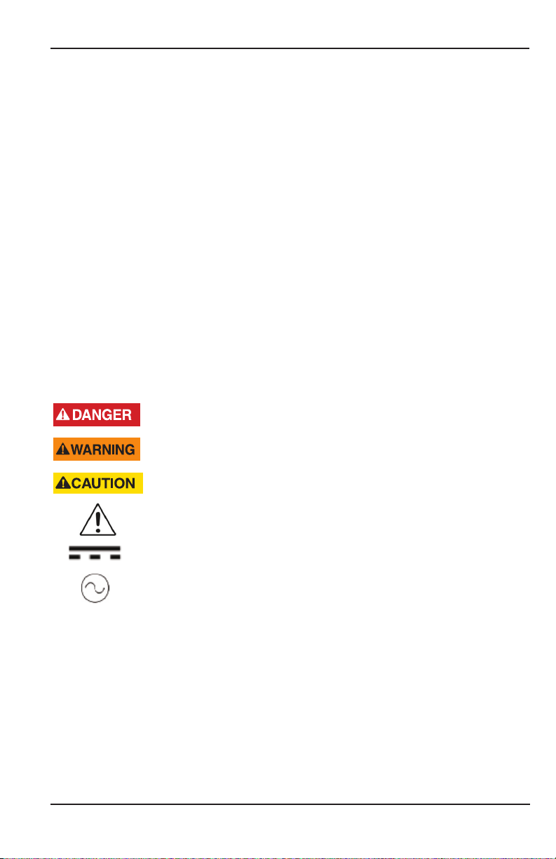
Panel-Mount Installations
OTE:N Mounting clips can accommodate a maximum panel thickness of
1�5 in� (38�1 mm)�
5.40 in.
(137.16 mm)
2.65 in.
(67.31 mm)
Figure 1: Panel cutout
3.07 in.
(78.00 mm)
Panel Cutout
5.38 in.
(136.65 mm)
3.50 in.
(89.00 mm)
2.54 in.
(64.52 mm)
6.22 in.
(158.00 mm)
Figure 2: Mounting dimensions
To install:
1� Measure and cut a mounting hole to the dimensions shown in Figure 1�
2� Verify that the gasket is secure inside the mounting bezel�
3� Insert the unit through the panel cutout�
4� Secure the unit to the panel with the provided mounting clips�
Page 10 March 2019CTL-UM-02038-EN-03
Page 11
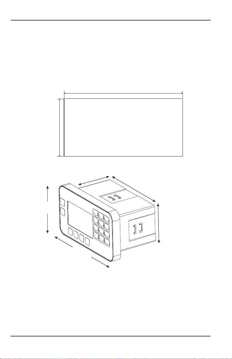
Wall-Mount Installations
8.00 in.
(203.20 mm)
6.00 in.
(152.40 mm)
Installing the BTU Monitor
4.88 in.
(123.95 mm)
8.75 in.
(222.25 mm)
9.65 in.
(242.83 mm)
9.38 in.
(238.25 mm)
Figure 3: FC-5000 BTU Monitor in an enclosure
9.38 in.
(238.25 mm)
To install the FC-5000 BTU Monitor on a wall, secure the enclosure to the wall with
four mounting screws (customer-supplied)�
Page 11 March 2019 CTL-UM-02038-EN-03
Page 12
Installing the BTU Monitor
Wiring the BTU Monitor
At installation, be sure to comply with the following requirements:
• Disconnect power to the unit before attempting any connection or service to
the unit�
• Avoid using machine power service for AC power� When possible, use a
dedicated circuit or a lighting circuit�
• Observe all local electrical codes�
• The unit must be wired with wires and/or cables with a minimum temperature
rating of 167° F (75° C)�
TO PREVENT ACCIDENTS, DO NOT APPLY POWER UNTIL ALL OTHER
CONNECTIONS HAVE BEEN COMPLETED.
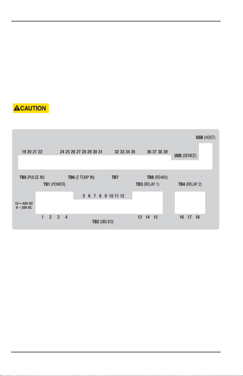
Terminal Connectors
Figure 4: Terminal connectors, analog out
OTE:N Terminal/pin descriptions shown on next page�
Page 12 March 2019CTL-UM-02038-EN-03
Page 13

Installing the BTU Monitor
The plug-in connectors on the rear panel of the FC-5000 BTU Monitor are:
Terminal
Block
TB1
Power
TB2
Digital I/O
TB3
Relay 1
TB4
Relay 2
TB5
Pulse Input
TB6
Temperature
Inputs
TB7
Scaled
Outputs
TB8
Comms
USB
Connection
Pin
1 +
2 SHLD
3 -
4 I/O GND
5 PWR +
6 I/O 1
7 I/O 2
8 I/O 3
9 I/O 4
10 I/O 5
11 I/O 6
12 I/O GND
13 N�O�
14 COM
15 N�C�
16 N�O� X1 N�O� X1
17 COM N�C� COM N�C�
18 N�C� X2 N�C� X2
19 EXCI +
20 IN +
21 SNS GND
22 SHLD
24 EXCI 1 +
25 SENS 1 +
26 SENS 1 27 EXCI 1 28 EXCI 2 +
29 SENS 2 +
30 SENS 2 31 EXCI 2 32 OUT 1 OUT 1
33 OUT 2 OUT 2
34 OUT GND A GND
35 SHLD SHLD
36 SHLD
37 38 +
39 485 GND
Device Mini-B Receptacle (Used for Firmware Updates)
Host Type-A Receptacle (Not Used)
P1-FC6A-*
Configurations/Part Numbers
FC5-BM-
FC5-BM-
P1-FA6A-*
FC5-BM-
P1-AC6A-*
FC5-BM-
P1-AA6A-*
Page 13 March 2019 CTL-UM-02038-EN-03
Page 14
Installing the BTU Monitor
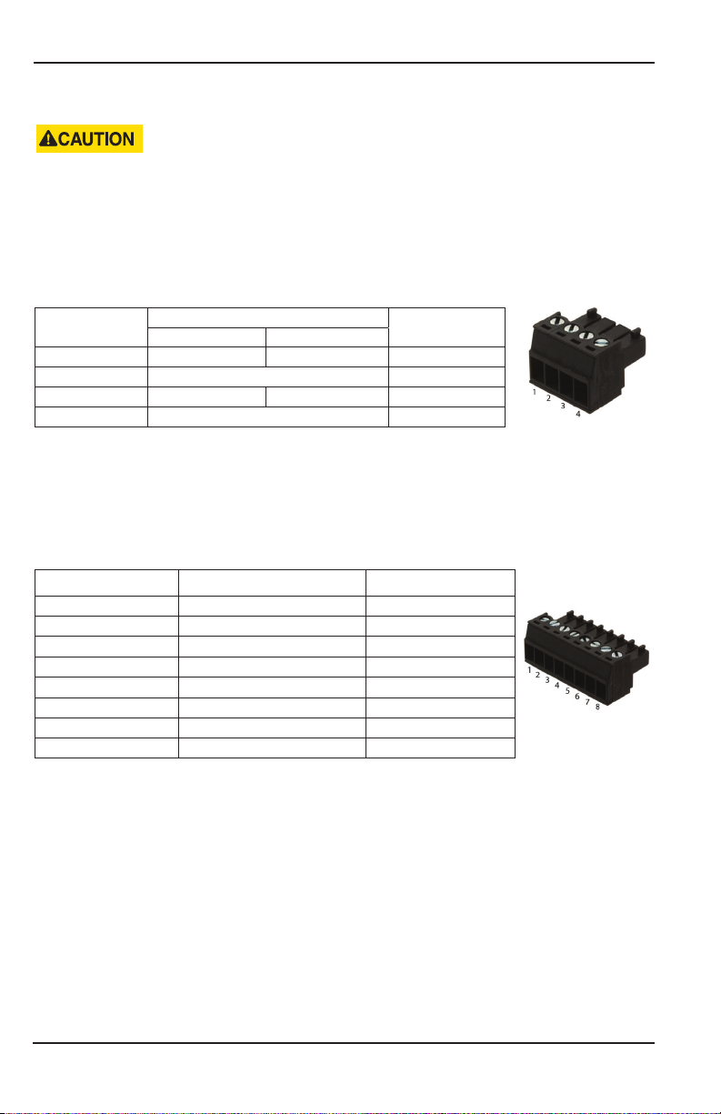
Power Input
THE FC5000 IS MICROPROCESSOR CONTROLLED. IT IS VERY IMPORTANT THAT THE
POWER SUPPLY BE FREE OF ELECTRICAL NOISE. AVOID USING POWER LINES THAT
FEED HEAVY LOAD ELECTRICAL DEVICES SUCH AS PUMPS AND MOTORS.
The FC-5000 BTU Monitor power input is internally fused and protected from
common line noise by a filtering network�
TB1 (POWER)
Connector Pin
1 Line (L) Positive (L+) 1
2 Shield (Chassis GND) 2
3 Neutral (N) Negative (L–) 3
4 Digital I/O GND 4
AC Power DC Power
Function
Table 1: Power input
Reference Pin
Temperature Inputs
Two temperature inputs allow the FC-5000 BTU Monitor to measure hydronic
energy usage with potentially varying temperature readings�
TB6 (2 TEMP IN)
Connector Pin Function Reference Pin
1 T1 Excitation (+) 24
2 T1 Sensor Input (+) 25
3 T1 Sensor Input (–) 26
4 T1 Excitation (–) 27
5 T2 Excitation (+) 28
6 T2 Sensor Input (+) 29
7 T2 Sensor Input (–) 30
8 T2 Excitation (–) 31
Table 2: Temperature inputs
OTE:N See Figure 5 on page 15 for a wiring diagram�
Page 14 March 2019CTL-UM-02038-EN-03
Page 15
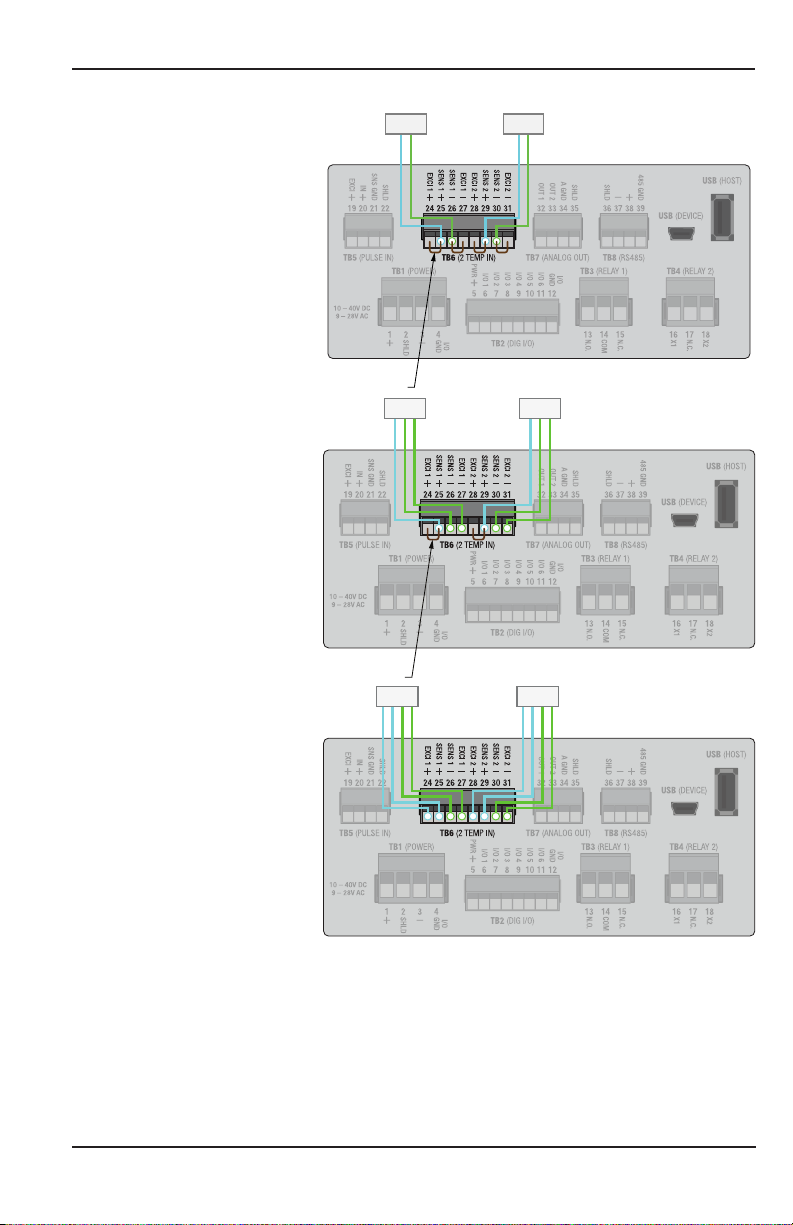
Installing the BTU Monitor
Jumper Wire
2-Wire RTD or Thermistor
3-Wire RTD
4-Wire RTD
RTD RTD
Jumper Wire
RTDRTD
RTDRTD
OTE:N The wires in your application may not be the same color as the wires in the
diagram� The number of each color represents the number of a color of
wire that your application will have� For example, the 3-Wire RTD diagram
has two green wires and one blue wire� Your application may have two
yellow wires and one red wire� To wire the system you would wire the two
yellow wires the same way the green wires are in the diagram, and the
same with the red and blue wires�
Figure 5: RTD Wiring Diagram
Page 15 March 2019 CTL-UM-02038-EN-03
Page 16
Installing the BTU Monitor
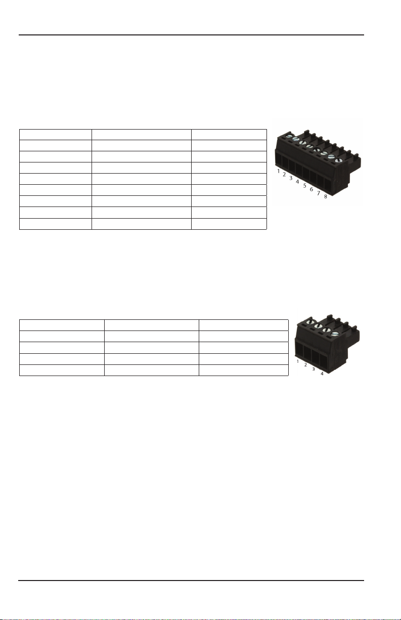
Digital Inputs
The FC-5000 BTU Monitor has six independent channels available for digital input�
The channels accept TTL voltage signals in the 0…5V DC range� The control inputs
are triggered when the voltage signal on the pin is pulled low (active low)� Input
range for a logic low signal is 0…1V, logic high is 4…5V�
TB2 (DIG I/O)
Connector Pin Function Reference Pin
1 Excitation or Power 5
2 Input/Output 1 Signal 6
3 Input/Output 1 Signal 7
4 Input/Output 1 Signal 8
5 Input/Output 1 Signal 9
6 Input/Output 1 Signal 10
7 Input/Output 1 Signal 11
8 Ground or Neutral 12
Table 3: Digital inputs
Communications
The FC-5000 BTU Monitor comes with Modbus (RTU or ASCII) and BACnet
communication protocols� Signals are transmitted over an EIA-485 (RS-485)
physical layer�
TB8 (RS-485)
Connector Pin Function Reference Pin
1 Shield (Chassis GND) 36
2 Negative (–) 37
3 Positive (+) 38
4 Output Ground 39
Table 4: Communications input
Page 16 March 2019CTL-UM-02038-EN-03
Page 17
Installing the BTU Monitor
Scaled Outputs
The FC-5000 BTU Monitor has two scaled output channels for use in applications
requiring remote data collection and/or monitoring� The outputs are firmware
configurable, and can be tied to parameters such as rates, temperature or
totalizer values�
TB7 (FREQ OUT) or (ANALOG OUT)
Connector Pin Function Reference Pin
1 Output 1 Signal 32
2 Output 2 Signal 33
3 Output Ground 34
4 Shield (Chassis GND) 35
Table 5: Scaled output channels
ANALOG OUTPUT CONFIGURATIONS ARE DESIGNED TO PROVIDE A SOURCING
OUTPUT SIGNAL. THE RECEIVING DEVICE MUST NOT PROVIDE POWER TO
THE LOOP.
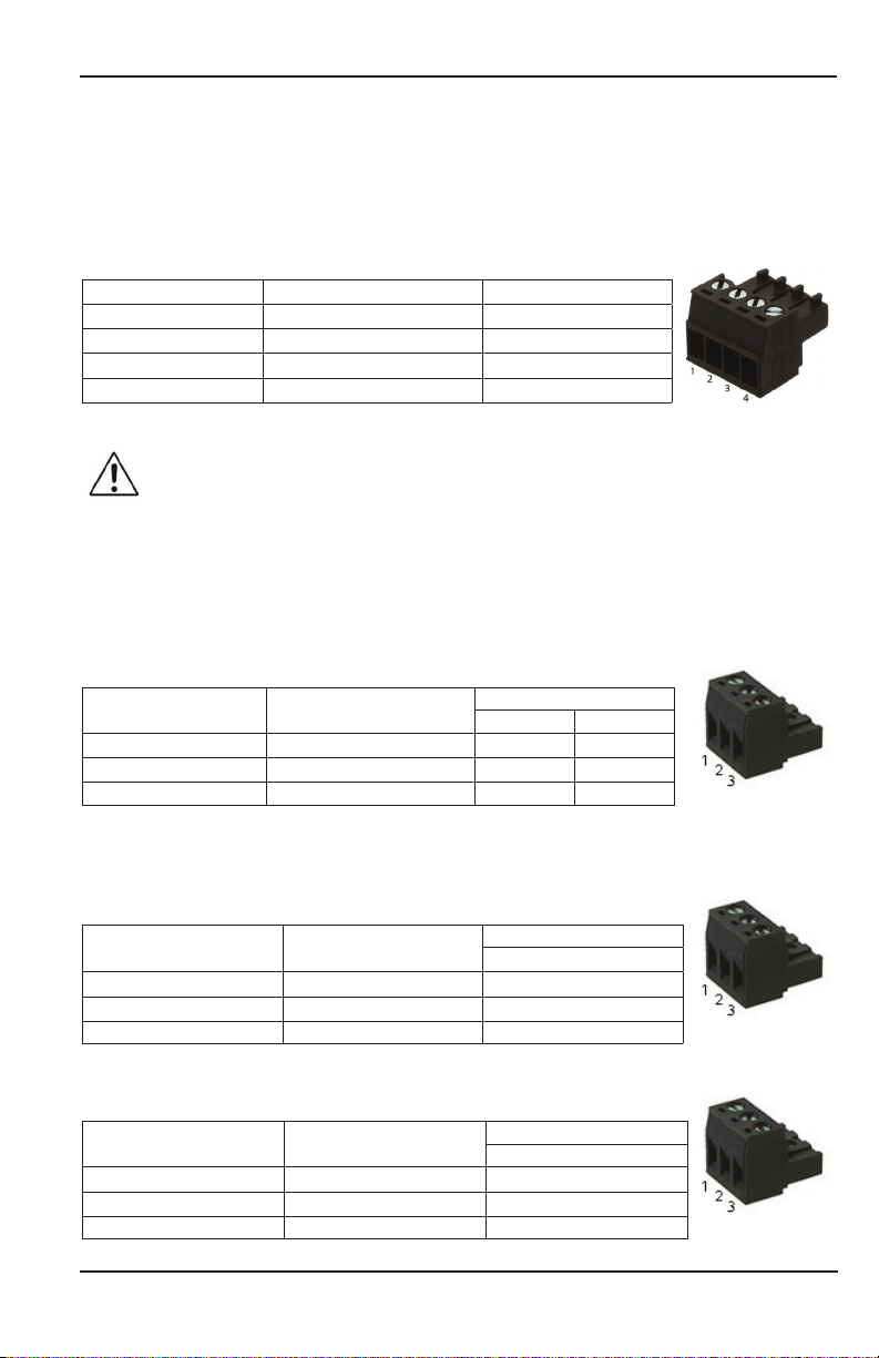
Relay Output Connectors
The FC-5000 BTU Monitor has either two Form C relay output terminals or one
Form C and one Form A terminal�
Two Form C
TB3 (RELAY 1) and TB4 (RELAY 2)
Connector Pin Function
1 Normally Open (N�O�) 13 16
2 Signal Common 14 17
3 Normally Closed (N�C�) 15 18
Table 6: Relay output connectors, relay option "C"
Reference Pin
Relay 1 Relay 2
One Form C and One Form A
TB3 (RELAY 1) - Form C
Connector Pin Function
1 Normally Open (N�O�) 13
2 Signal Common 14
3 Normally Closed (N�C�) 15
Figure 6: Form C Relay Output Connector
TB4 (RELAY 2) - Form A
Connector Pin Function
1 Connection Point 1 16
2 Not Used (No Contact) 17
3 Connection Point 2 18
Figure 7: Form A Relay Output Connector
Reference Pin
Relay 1
Reference Pin
Relay 2
Page 17 March 2019 CTL-UM-02038-EN-03
Page 18

Installing the BTU Monitor
Flow Sensor Input
The FC-5000 BTU Monitor is designed to accept pulses from open collector
transistors or dry contact closure transmitters�
Before making any connections:
• Always use shielded wire to protect the signal line from external noise (ground
shield to terminal #3)�
• Make sure the signal lines are not bundled with or touching power lines�
OTE:N In the table below, RF Pin refers to RF type pickups/amplifiers�
TB5 (PULSE IN)
Connector
Pin
1 Sensor Exitation (+) 19 A
2 Sensor Input (+) 20 C
3 Sensor Input/Common (–) 21 B
4 Shield (Chassis GND) 22 —
Function Reference Pin RF Pin
Table 7: Flow sensor input
Powering Radio Frequency (RF) Type Pickups
Radio Frequency (RF) type pickups require a power source to generate a radio
frequency field� Similar to magnetic pickups, as fluid velocity provides rotational
energy on the flow meter rotor, the field generated by the pickup is disturbed,
producing output pulses that are proportional to flow rate�
OTE:N Maximum current draw from the Excitation pin cannot exceed 200 mA� RF
style pickups will require a signal conditioning amplifier�
0…5V, 0…10V Configuration Source Voltage Configuration
From
Pickup/
Amplier
Table 8: Pickup configurations
From
Pickup/
Amplier
Page 18 March 2019CTL-UM-02038-EN-03
To
BTU
Monitor
Page 19

Operator Interface
OPERATOR INTERFACE
Keypad and Soft Keys
The keypad and soft keys are for programming, editing and changing views�
Scrolling
The screens can display up to four lines at a time� Some menus have more than
four items to display� To see the off-screen items, press UP/DOWN to scroll
through the entire list�
THE BTU MONITOR MAY BE OPERATED ONLY BY PERSONNEL WHO ARE AUTHORIZED
AND TRAINED BY THE FACILITY. OBSERVE ALL INSTRUCTIONS IN THIS MANUAL. OBEY
ALL SAFETY PRECAUTIONS MENTIONED IN “SAFETY CONSIDERATIONS” ON PAGE 5.
Control Panel Keys
OTE:N Always press (ENTER) to save a new value�
The numbered keys are used to enter or change parameter values�
In editing mode, BACKSPACE deletes the character to the left of the
cursor� While navigating, BACKSPACE moves to a previous
menu selection�
Depending on the current screen, ENTER:
• Saves the current value and ends the editing session
• Advances deeper into the menu structure
• Toggles enumerations
The UP/DOWN keys:
• Toggle the display views on the home screen
• While editing, use UP/DOWN to advance the cursor to the right or left
• In the menu structure, scroll through the menus and parameters
The F1-F4 function keys are soft keys that change
function to whichever icon is present above them�
See “Icon Functionality” on page 20�
Table 9: Control panel keys
Page 19 March 2019 CTL-UM-02038-EN-03
Page 20

Operator Interface
Icon Functionality
Depending on the task being performed, one or more of the following icons may
appear on the screen� To activate an icon, press the Function key (F1, F2, F3 or F4)
directly under the icon, where applicable�
Icon Function
Display the Home screen or cancel an edit (if you press the button without saving first)
Display the menu structure
Create a custom label (name) for a unit of measure
Return to Setup menu
Cycle through alpha characters
Enter a decimal point
Cycle through special characters
Reveal raw and calculated info/sensor data for the BTU Monitor
Clear the selected value or cancel edit (press twice, consecutively)
Enter conversion factor for custom unit of measure
Change selected value to positive ( + ) or negative ( – )
Set totalizer rollover point
Appears on Home screen for various events� Refer to “Troubleshooting” on page 43 for
details�
Table 10: Icon functionality
Page 20 March 2019CTL-UM-02038-EN-03
Page 21

Numeric Editing
On-screen
instruction
Move cursor
to the right
Existing
Value
Move cursor
to the left
New
Value
FC-5000
Operator Interface
Delete
character
to the left
OR
Return to
previous
menu
Save value
Return to
parent setup
screen
Alpha-Numeric Editing
On-screen
instruction
Move cursor
to the right
Existing
value
Move cursor
to the left
New
value
Return to
parent
setup
screen
Cycle
through
letters
Make entry
positive or
negative
Add a
decimal
point
Clear entire new value or
cancel edit (press twice, consecutively)
Figure 8: Numeric editing
Cycle
through
Clear entire new value or
cancel edit (press twice, consecutively)
special
characters
Figure 9: Alpha-numeric editing
Delete
character
to the left
OR
Return to
previous
menu
Save value
Page 21 March 2019 CTL-UM-02038-EN-03
Page 22

Operator Interface
Selection/Enumeration Editing
OTE:N Depending on the menu, the selection during an enumeration style edit
may appear different�
Save/Select
Move up or
down in
menu
Return to
parent setup
screen
Create a
custom
label
Enter
conversion
factor
Figure 10: Selection editing
Set totalizer
rollover point
Conrmation Screen
No
Figure 11: Confirmation screens
Page 22 March 2019CTL-UM-02038-EN-03
Yes
Page 23

Operator Interface
Navigating the Menus
The Home screen display shows rates and totals, either separately or
simultaneously� Status and alarm messages or alarm icons appear on the display
when appropriate�
Press UP/DOWN to toggle views on the Home screen:
• Flow Rate
• Flow Total
• Energy/BTU Rate
• Energy/BTU Total
Figure 12: Single display
• Flow Rate and Flow Total
• Energy/BTU Rate and
Energy/BTU Total
Figure 13: Dual display
Press F1 to enter the Main menu to access Setup and System Information, or press
F2 to enter the INFO/SENSOR DATA menu�
Page 23 March 2019 CTL-UM-02038-EN-03
Page 24

Operator Interface
Menu Structure
The available menu items depend on the BTU Monitor configuration� Each menu
item is explained in detail in the following pages�
HOME
SCREEN
MAIN MENU
DISPLAY
Language
Contrast
Brightness
Temperature Units
Energy Rate Units
Energy Total Units
SYSTEM
INFORMATION
Function
Part Number (P.N.)
Serial Number (S.N.)
MFG Date
Logic Board
Power Board
Starttime
UNITS
Flow Rate Units
Flow Total Units
Vendor
Model
Version
Uptime
Ontime
SETUP
ADVANCED
SETUP
SENSOR INPUT
Flow Sensor Type
Flow Sensor Calibration
Flow Sensor Properties
Temperature Sensor 1 Type
Temperature Sensor 1 Calibration
Temperature Sensor 2 Type
Temperature Sensor 2 Calibration
SCALED OUTPUT
Output 1 Mode
Output 1 Settings
Output 2 Mode
Output 2 Settings
DIGITAL I/O
Disabled
Reset Relay 1
Reset Relay 2
Reset Flow Total
Reset R1/Flow Total
Reset R2/Flow Total
Reset Energy Total
Reset R1/Energy Total
Reset R2/Energy Total
RELAY OUTPUT
Relay 1 Mode
Relay 2 Settings
Relay 2 Mode
Relay 2 Settings
Figure 14: Menu structure
Page 24 March 2019CTL-UM-02038-EN-03
RESETS
Reset Flow Total
Reset Energy Total
Reset Faults
Reset Defaults
PASSCODE SETUP
Setup Menu Passcode
Reset Menu Passcode
FLUID PROPERTIES
Fluid ID
Heat Transfer Fluid
Communications
Network Type
*Network settings vary
based on the Network
Type that is selected
Page 25

Info/Sensor Data
INFO/SENSOR DATA
The FC-5000 BTU Monitor features a quick method to view measured data
transmitting to and from the device� You can use the data for informational
purposes or for troubleshooting� The type of data displayed can include raw input
frequency, relay status or calculated data, such as flow rate�
Item Description
FLOW FREQ Raw frequency of the flow sensor
FLOW COUNT Raw pulse count of the flow sensor
FLOW RATE Calculated flow rate of the flow sensor
FLOW TOT Calculated flow total of the flow sensor
ENERGY RATE Calculated energy rate
ENERGY TOT Calculated energy total
TEMP 1
TEMP 2
DELTA T The difference between TEMP 1 and TEMP 2
DENSITY Density of the fluid (Programmed)
SP HT Specific heat of the fluid (Programmed)
RELAY 1 ENERGIZED/OFF status of relay 1
RELAY 2 ENERGIZED/OFF status of relay 2
D-I/O 1 ENABLED/DISABLED status of digital I/O port 1
D-I/O 2 ENABLED/DISABLED status of digital I/O port 2
D-I/O 3 ENABLED/DISABLED status of digital I/O port 3
D-I/O 4 ENABLED/DISABLED status of digital I/O port 4
D-I/O 5 ENABLED/DISABLED status of digital I/O port 5
D-I/O 6 ENABLED/DISABLED status of digital I/O port 6
Displays the calculated temperature and raw resistance (ohms) value of
temperature sensor 1�
Displays "NO SENSOR" if no sensor is connected�
Displays the calculated temperature and raw resistance (ohms) value of
temperature sensor 2�
Displays "NO SENSOR" if no sensor is connected�
To return to the home screen, press BACKSPACE or F1 (home)�
Figure 15: Info/sensor data screen
Page 25 March 2019 CTL-UM-02038-EN-03
Page 26

System Information
SYSTEM INFORMATION
The System Information menu contains build information specific to the
configuration of the unit�
To view your system information, navigate to System Information from
the Main menu�
Item Description
VENDOR Manufacturer of the product
MODEL Product family/series
FUNCTION For factory/diagnostic purposes only
P�N� Configured part number
S�N� Serial number
MFG DATE The original manufacture/build date
VERSION Loaded firmware version
LOGIC BRD For factory/diagnostic purposes only
POWER BRD For factory/diagnostic purposes only
UPTIME Time, in seconds, since last power-on session start
ONTIME Total lifetime power-on, in seconds
STARTTIME Ontime at start of power-on session
Table 11: System information menu
Figure 16: System information screen
Page 26 March 2019CTL-UM-02038-EN-03
Page 27

Basic Setup
BASIC SETUP
Display
Use this menu to change the display settings for Language, Contrast or Brightness�
1� Navigate to Display from the main menu�
2� Press UP/DOWN to scroll through the available display parameters, then
press ENTER�
3� Scroll through available options, then press ENTER to select and save
your changes�
Figure 17: Display configuration screen
Resets
Use this menu to reset Totalizers, Faults, Defaults and latched relays:
1� Navigate to Resets from the main menu�
OTE:N If a passcode was configured, enter the passcode, then press ENTER to
access this menu�
2� Press UP/DOWN to scroll through the available reset options, then
press ENTER�
3� On the conrmation screen press ENTER to conrm the reset�
Figure 18: Resets menu
Page 27 March 2019 CTL-UM-02038-EN-03
Page 28

Basic Setup
Clearing a Latched Relay
To clear a relay that latches after a trigger:
1� Navigate to the main menu�
2� Press UP/DOWN to scroll to UNLATCH R1 or UNLATCH R2, then press ENTER�
Passcode Setup
Enabling Passcodes
FC-5000 units are shipped without passcode protection enabled� You can enable a
unique password for the Setup Menu and the Reset Menu� To enable a passcode:
1� Navigate to SETUP > PASSCODE SETUP�
2� Press UP/DOWN to scroll to the passcode you want to enable, then
press ENTER�
Figure 19: Enable passcode screen
3� Enter a numeric passcode from 4 to 8 digits in length, then press ENTER�
4� On the conrmation screen, press ENTER again to conrm the passcode�
OTE:N An asterisk ( * ) appears next to each passcode if it is enabled�
Figure 20: Asterisk indicates enabled passcode
Page 28 March 2019CTL-UM-02038-EN-03
Page 29

Basic Setup
Disabling a Passcode
1� Navigate to SETUP > PASSCODE SETUP�
2� Press UP/DOWN to scroll to the passcode you want to delete, then press
F4 (clear)�
3� On the conrmation screen, press ENTER to conrm removal of the passcode�
Forgotten Passcodes
If you have forgotten your passcode, call Badger Meter customer service and they
will be able to assist you in resetting the passcode�
1� Navigate to System Information from the main menu�
2� Locate and write down the valves shown for "STARTTIME" and "S�N�
(Serial Number)"�
3� Call Badger Meter customer service� See “Troubleshooting” on page 43 for
contact information�
Units
Use the UNITS menu to configure units of measure, display precision (resolution)
and radix (comma or decimal point)� You can configure these settings for each
Parameter Unit: Flow (Rate and Total), Temperature and Energy (Rate and Total)�
1� Navigate to SETUP > UNITS�
2� Press UP/DOWN to scroll through the available parameter units�
3� Scroll to Unit of Measure, Display Precision or Radix, then press ENTER to
activate the drop-down menu for that setting�
Unit of Measure
The Unit of Measure setting determines the engineering unit and/or time interval
for calculated measurements of the selected parameter unit�
1� Press UP/DOWN to scroll through the available units of measure, then press
ENTER to select and save the new setting�
OTE:N For most rate measurements, all options are available in time intervals of
seconds (S), minutes (M), hours (H) and days (D)�
For any of the Flow parameters (Rate or Total), the available units are:
Unit Description Unit Description
US GAL US Gallon M
IG Imperial Gallon AC-FT Acre Feet
MG US Million Gallons BBL Oil Barrels [42 US Gallons]
MIG Imperial Million Gallons FBBL Liquid Barrels [31�5 US Gallons]
L Liters US OZ US Ounces
ML Million Liters I OZ Imperial Ounces
3
FT
Cubic Feet CUST Custom
Table 12: Flow units
3
Cubic Meters
Page 29 March 2019 CTL-UM-02038-EN-03
Page 30

Basic Setup
For Energy Rate the available units are:
Unit Description Unit Description
kBTU/H Thousand BTU per Hour Ton (RT) 12,000 BTU/H
BTU/MIN BTU per Minute J/S Joules per Second
KW Kilowatts CUST Custom
Table 13: Energy rate units
For Energy Total the available units are:
Unit Description Unit Description
BTU British Thermal Unit MWH Megawatt Hour
kBTU 1000 BTU KJ Kilojoule
MMBTU Million BTU TON(RT)-H 12,000 BTU/H Hour
KWH Kilowatt Hour CUST Custom
Table 14: Energy total units
For Temperature the available units are:
Unit Description Unit Description
°F Degrees Fahrenheit °C Degrees Celsius
K Kelvin R Rankine
Table 15: Temperature units
Creating Custom Units for Rate or Total Measurement
1� Follow the procedure outlined in “Unit of Measure” on page 29 to enter the
Unit of Measure menu for a parameter�
2� Press UP/DOWN to choose CUST, then press ENTER�
OTE:N The display populates with additional icons that need to be modified for
custom units�
3� Press F2 (custom label)� Use the soft keys in conjunction with the numeric
keypad and UP/DOWN to create a custom label, then press ENTER�
OTE:N See Table 9 on page 19 and Table 10 on page 20 for button functionality�
4� On the conrmation screen, press ENTER to conrm the new custom unit� The
new label displays in the selection list�
5� Press F3 (conversion) to assign a conversion factor for this custom unit� The
number entered will be a factor related to the specic parameter�
◊ FLOW RATE: GAL/MIN
◊ FLOW TOTAL: GALLONS (GAL)
◊ ENERGY RATE: BTU/MIN
◊ ENERGY TOTAL: BTU
◊ TEMPERATURE: ° F (Fahrenheit)
6� Press ENTER to save the change�
7� On the conrmation screen, press ENTER to conrm the change�
OTE:N For example, if making a custom unit for Energy Rate and 2 is programmed
as a conversion factor, the custom unit is equivalent to 2 BTU/MIN� If 0�5 is
entered, the custom unit is equivalent to 0�5 BTU/MIN�
Page 30 March 2019CTL-UM-02038-EN-03
Page 31

Basic Setup
Display Precision
The Display Precision setting determines the resolution of a value, indicated by the
number of digits after the decimal place, for the selected parameter unit�
1� Press UP/DOWN to scroll to DISPLAY PRECISION, then press ENTER�
2� Scroll through the available options (0…4), then press ENTER to select and
save the change�
Radix
The Radix parameter determines if a period or comma is used to represent a
decimal place for the selected parameter unit�
1� Press UP/DOWN to scroll to RADIX, then press ENTER�
2� Scroll through available options (decimal point or comma), then press ENTER
to select and save the change�
Page 31 March 2019 CTL-UM-02038-EN-03
Page 32

Advanced Setup
ADVANCED SETUP
Use the ADVANCED SETUP menu to configure flow meters, temperature sensors,
outputs, relays and communication�
Conguring a Flow Sensor
Flow Sensor Type
See "Flow Sensor Types" on page 46 for more details on flow type selection for
Badger Meter products� Use this menu to select the flow meter that the device is
connected to�
1� Navigate to SETUP > ADVANCED SETUP > SENSOR INPUTS�
2� Press UP/DOWN to scroll to FLOW SENSOR TYPE, then press ENTER�
3� Scroll through the available sensor types, then press ENTER to select and save
the new settings�
The ow sensor types are shown in Table 16�
Option Description
NO SENSOR/
DISABLED
SINE:
K-FACTOR
PULSE:
K-FACTOR
PULSE:
K-FACTOR
PULLUP
PULSE:
DEBOUNCE
K-FACTOR
PULSE:
DIC
Page 32 March 2019CTL-UM-02038-EN-03
Disables the sensor input in the firmware
• Frequency input channel
◊ Examples: Mag pick-offs, Low level signals (~100 mV)
• Single K-Factor entry
• Pulse input channel
◊ Any pulse producing sensor
◊ Examples: TTL, RF carriers w/ amplifier
• Single K-Factor entry
• Active sensor: No pullup resistor
• Pulse input channel
◊ Any pulse producing sensor
◊ Examples: TTL, RF carriers w/ amplifier
• Single K-Factor entry
◊ Pulses per unit of volume
• Passive sensor: Pullup resistor to 12V for excitation
• Unique to products with raw reed switches
• Pulse input channel
◊ Any pulse producing sensor coupled with a reed switch
◊ Example: Industrial Oval Gear
• Single K-Factor entry
◊ Pulses per unit of volume
• Passive sensor: Pullup resistor to 12V for excitation
• Unique to the Data Industrial (DIC) product line
• Pulse input channel
◊ Any pulse producing sensor
◊ Examples: TTL, RF carriers w/ amplifier
• K & Offset values entered
◊ K = unit of volume per pulse
• Active sensor: No pullup resistor
Table 16: Flow sensor types
Page 33

Advanced Setup
Flow Sensor Calibration
Use this menu to change the calibration settings (K-factor, offset and low flow
cutoff) for the selected Flow Meter Type�
1� Navigate to SETUP > ADVANCED SETUP > SENSOR INPUTS�
2� Press UP/DOWN to scroll to FLOW SENSOR CAL, then press ENTER�
3� Scroll to and edit each option, as necessary� The options include:
Option Description
K-FACTOR A singular K-factor entry point�
OFFSET Used to apply an offset to sensor input calibration
LOW FLOW
CUTOFF
The point at which the display reads zero� Represented in configured unit of measure
Table 17: Flow sensor calibration options
Flow Sensor Properties
Use this menu to change flow meter damping� Damping is a smoothing
coefficient� As the number increases, averaging becomes greater� As the number
decreases, it approaches the raw reading� Valves range from 0…10�
1� Navigate to SETUP > ADVANCED SETUP > SENSOR INPUTS�
2� Press UP/DOWN to scroll to FLOW SENSOR PROP, then press ENTER�
3� Press ENTER to select the DAMPING option and edit it�
OTE:N Each time you press ENTER, the value (0…10) will increase� If the value is
10, pressing ENTER again will restart the list at 0�
Page 33 March 2019 CTL-UM-02038-EN-03
Page 34

Advanced Setup
Conguring a Temperature Sensor
Temperature Sensor Type
Use this menu to select the temperature sensor type the device is connected to�
1� Navigate to SETUP > ADVANCED SETUP > SENSOR INPUTS�
2� Press UP/DOWN to scroll to either temperature sensor, then press ENTER�
OTE:N In most applications, Temperature Sensor 1 is used for the supply line, and
Temperature Sensor 2 is used for the return line�
3� Scroll through the available sensor types, the press ENTER to select and save
the new setting�
The temperature sensor types are shown in Table 18�
OTE:N TCR is the temperature coefficient of resistance�
Option Description
NO SENSOR/DISABLED No sensor� Disables the input in the firmware
2-WIRE RTD: PT100 (385) 2-Wire RTD; 100 Ohm; Platinum; 0�0385 TCR
2-WIRE RTD: CUSTOM 2-Wire RTD; Custom Calibration
3-WIRE RTD: PT100 (385) 3-Wire RTD; 100 Ohm; Platinum; 0�0385 TCR
3-WIRE RTD: CUSTOM 3-Wire RTD; Custom Calibration
4-WIRE RTD: PT100 (385) 4-Wire RTD; 100 Ohm; Platinum; 0�0385 TCR
4-WIRE RTD: CUSTOM 4-Wire RTD; Custom Calibration
4-WIRE RTD: PT1000 (385) 4-Wire RTD; 1000 Ohm; Platinum; 0�0385 TCR
2-PT RTD: CUSTOM Platinum RTD with 2-point calibration
THERMISTOR: DI TYPE Data Industrial thermistor configuration
THERMISTOR: CUSTOM Custom Thermistor
Table 18: Temperature sensor types
Temperature Sensor Calibration
Use this menu to change calibration settings for the respective Temperature
Sensor Type�
OTE:N This menu is only available when a custom temperature sensor type
is selected�
1� Navigate to SETUP > ADVANCED SETUP > SENSOR INPUTS�
2� Press UP/DOWN to scroll to the temperature sensor calibration setting for the
respective temperature sensor type, then press ENTER�
3� Scroll to and edit each option, as necessary�
Page 34 March 2019CTL-UM-02038-EN-03
Page 35

Advanced Setup
The calibration setting options are described below� The settings that appear on
the device are relative to the sensor type and will only show if a sensor type
is chosen�
Temperature
Sensor Type
2, 3 and
4-Wire RTDs
2-PT RTD:
Custom
Thermistor
Option Description
ALPHA COEFF
Callendar-Van Dusen coefficientsBETA COEFF
DELTA COEFF
OHMS: LOW Resistance (Ω) at 0° C / Resistance (Ω) at "TEMP: LOW"
TEMP: LOW Temperature at "OHMS: LOW" (° C)
OHMS: HIGH Resistance (Ω) at temperature "TEMP: HIGH"
TEMP: HIGH Temperature at "OHMS: HIGH" (° C)
OFFSET Temperature calibration offset
COEFF A
Steinhart-Hart coefficientsCOEFF B
COEFF C
Table 19: Temperature sensor calibration descriptions
OTE:N The temperature sensor calibration for Temperature Sensor 2 includes an
adjustment field "TEMP 2 ADJ (° F)"� Changing this setting will increase or
decrease the temperature variance by the value entered, in
degrees Fahrenheit�
Conguring Outputs
Scaled Outputs: Output Mode
Use this menu to change the mode of one or both scaled outputs� The mode
defines the behavior of the output�
1� Navigate to SETUP > ADVANCED SETUP > SCALED OUTPUTS
2� Press UP/DOWN to scroll to an output mode, then press ENTER�
3� Scroll through the available modes, then press ENTER to select and save
the setting�
The Output Mode options will vary based on device conguration�
Device Configuration Option Description
Frequency Output
FC5-BM-**-F***-*
Analog Output
FC5-BM-**-A***-*
NO OUTPUT/DISABLED Disables Output
PULSE: TOTAL Sends pulse(s)-per-total unit of measure
PULSE: RATE Sends pulse(s)-per-rate unit of measure
NO OUTPUT/DISABLED Disables Output
ANALOG: 0…5V
ANALOG: 0…10V
ANALOG: 4…20 mA
Table 20: Output mode options
0…5V output signal, scaled to an
output source
0…10V output signal, scaled to an
output source
4…20 mA output signal, scaled to an output
source
Page 35 March 2019 CTL-UM-02038-EN-03
Page 36

Advanced Setup
Scaled Outputs: Output Settings
Use this menu to change the output settings for the respective output mode�
1� Navigate to SETUP > ADVANCED SETUP > SCALED OUTPUTS�
2� Press UP/DOWN to scroll to the applicable output settings, then press ENTER�
3� Scroll to and edit each option, as necessary�
a� If using the frequency output configuration
Output Mode Option Description
Parameter assignment of the output
(such as rate, total or temperature)
Minimum parameter value associated with
output minimum
Maximum parameter value associated with
output maximum
Maximum frequency output value
Parameter assignment of the output
(such as rate, total or temperature)
(Read Only) Number of transmitted pulses
Table 21: Frequency output settings
PULSE: RATE
PULSE: TOTAL
OUTPUT SOURCE
SCALE MINIMUM
SCALE MAXIMUM
MAXIMUM
FREQUENCY
OUTPUT FREQ (Read Only) Real-time output frequency
OUTPUT SOURCE
SCALING FACTOR Units of measure transmitted, per pulse
SCALED PULSE
COUNT
b� If using the analog output configuration
Option Description
OUTPUT SOURCE
ANALOG FULL SCALE Maximum value associated with output maximum
ANALOG LOW SCALE Minimum value associated with output minimum
Parameter assignment of the output
(such as rate, total or temperature)
Table 22: Analog output settings
Relay Outputs: Relay Mode
Use this menu to change the mode of one or both relay outputs� The mode
defines the behavior of the output�
1� Navigate to SETUP > ADVANCED SETUP > RELAY OUTPUTS.
2� Press UP/DOWN to scroll to an output mode, then press ENTER�
3� Scroll through the available modes, then press ENTER to select and save
the setting�
Option Description
NO RELAY/DISABLED Disables output
TOTALIZER Totalizer output
ALARM: HIGH On/Off function, energized at the high set point
ALARM: LOW On/Off function, energized at the low set point
ALARM: RANGE On/Off function, energized beyond high and low set points
MANUAL On/Off function of manual operation
Table 23: Relay mode options
Page 36 March 2019CTL-UM-02038-EN-03
Page 37

Advanced Setup
Relay Outputs: Relay Settings
Use this menu to change the relay settings for the respective relay mode�
1� Navigate to SETUP > ADVANCED SETUP > RELAY OUTPUTS�
2� Press UP/DOWN to scroll to the applicable relay setting, then press ENTER�
3� Scroll to and edit each option, as necessary�
OTE:N Alarm icons "R1" and "R2" will appear in the upper right section of the
Home Screen to provide a local indication when a relay condition has been
met and when the relay has be energized�
Output Mode Option Description
OUTPUT SOURCE Parameter assignment (e�g� Flow Total or Energy Total)
TOTALIZER
ALARM: HIGH
ALARM: LOW
SCALING FACTOR Pulse(s) transmitted per unit of measure
UNITS Converts output unit of measure
PULSE WIDTH Time between the rising and falling edges of a single pulse
OUTPUT SOURCE Parameter assignment (such as Flow Rate or Temperature)
HIGH SETPOINT
HYSTERESIS HI
SET DELAY
RELEASE DELAY
LATCHING
OUTPUT SOURCE Parameter assignment (such as Flow Rate or Temperature)
LOW SETPOINT
HYSTERESIS LO
SET DELAY
RELEASE DELAY
LATCHING
Instructs the device to energize the relay if this value reached/
exceeded� This value is linked to the OUTPUT SOURCE and its unit
of measure (for example, Flow Rate in GPM)
Creates a window/zone below the HIGH SETPOINT value where
the relay remains in an energized state
Time in seconds that will elapse before the relay energizes, if the
HIGH SETPOINT value is reached/exceeded
Time in seconds that the relay will remain energized, if the
HYSTERESIS HI value is reached/exceeded
Leaves the relay in an energized state until it is manually cleared
on the device, either through the keypad interface or through
the Digital I/O channels
Instructs the device to energize the relay if this value reached/
exceeded� This value is linked to the OUTPUT SOURCE and its unit
of measure (for example, Flow Rate in GPM)
Creates a window/zone above the LOW SETPOINT value where
the relay remains in an energized state
Time in seconds that will elapse before the relay energizes, if the
LOW SETPOINT value is reached/exceeded
Time in seconds that the relay will remain energized, if the
HYSTERESIS LO value is reached/exceeded
Leaves relay in an energized state until it is manually cleared on
the device, either through the keypad interface or through the
Digital I/O channels
Page 37 March 2019 CTL-UM-02038-EN-03
Page 38

Advanced Setup
Output Mode Option Description
OUTPUT SOURCE Parameter assignment (such as Flow Rate or Temperature)
HIGH SETPOINT
HYSTERESIS HI
LOW SETPOINT
ALARM: RANGE
HYSTERESIS LO
SET DELAY
RELEASE DELAY
LATCHING
MANUAL OVERRIDE
Instructs the device to energize the relay if this value reached/
exceeded� This value is linked to the OUTPUT SOURCE and its unit
of measure (for example, Flow Rate in GPM)
Creates a window/zone below the HIGH SETPOINT value, where
the relay remains in an energized state
Instructs the device to energize the relay if this value reached/
exceeded� This value is linked to the OUTPUT SOURCE and its unit
of measure (for example, Flow Rate in GPM)
Creates a window/zone above the LOW SETPOINT value, where
the relay remains in an energized state
Time in seconds that will elapse before the relay energizes, if
either setpoint value is reached/exceeded
Time in seconds that the relay will remain energized, if either
hysteresis value is reached/exceeded
Leaves relay in an energized state until it is manually cleared on
the device, either through the keypad interface or through the
Digital I/O channels
Bypasses any programmed triggers to trigger the relay, which
will remain triggered until deactivated
Table 24: Relay settings
Page 38 March 2019CTL-UM-02038-EN-03
Page 39

Advanced Setup
Conguring Digital I/O
The FC-5000 BTU Monitor has remote reset capabilities for relays and totalizers
through any one of six different channels�
All six channels are input-only and can be configured for any combination of
the following�
Option Description
DISABLED The I/O channel will have no function
RESET: RELAY 1 Resets latch on Relay 1
RESET: RELAY 2 Resets latch on Relay 2
RESET: ALL RELAYS Resets latches on Relays 1 and 2
RESET: FLOW TOTAL Resets Flow Total
RESET: ENERGY TOTAL Resets Energy Total
RESET: RELAY 1 AND FLOW TOTAL Resets latch on Relay 1 and resets Flow Total
RESET: RELAY 2 AND FLOW TOTAL Resets latch on Relay 2 and resets Flow Total
RESET: RELAY 1 AND ENERGY TOTAL Resets latch on Relay 1 and resets Energy Total
RESET: RELAY 2 AND ENERGY TOTAL Resets latch on Relay 2 and resets Energy Total
RESET: FLOW/ENERGY TOTALS Resets Flow Total and Energy Total
RESET: ALL RELAYS AND ALL TOTALS Resets Relay 1, Relay 2, Flow Total and Energy Total
Table 25: Channel options
Figure 21: Digital I/O menu
1� Navigate to SETUP > ADVANCED SETUP > DIGITAL I/O�
2� Press UP/DOWN to scroll to any of the six input channels�
3� Press ENTER repeatedly until the desired function appears� Each time ENTER is
pressed, the channel toggles through the available functions�
To disable any channel, simply highlight the digital I/O channel, and press ENTER
until DISABLED appears�
Page 39 March 2019 CTL-UM-02038-EN-03
Page 40

Advanced Setup
Conguring Fluid Properties
The Fluid Properties menu configures the device for the fluid medium that is
being measured�
Figure 22: Fluid properties menu
Fluid ID
Use this menu to enter a user-defined text entry for naming or identification�
1� Navigate to SETUP > ADVANCED SETUP > FLUID PROPERTIES�
2� Press UP/DOWN to select FLUID ID, then press ENTER�
3� Use the soft keys and numeric keypad to enter the desired name, then press
ENTER to save�
4� On the conrmation screen, press ENTER to conrm any changes�
Heat Transfer Fluid
Use this menu to select from a list of pre-programmed fluid types� A custom
option is available�
1� Navigate to SETUP > ADVANCED SETUP > FLUID PROPERTIES�
2� Press UP/DOWN to select HEAT TRANSFER FLUID, then press ENTER�
3� Scroll through the available options, then press ENTER to save the change�
Option Description
WATER Water only�
20% PROPYLENE GLYCOL 20% Propylene Glycol / 80% water mixture
30% PROPYLENE GLYCOL 30% Propylene Glycol / 70% water mixture
50% PROPYLENE GLYCOL 50% Propylene Glycol / 50% water mixture
CUSTOM FLUID Custom fluid (requires additional settings)
Table 26: Heat Transfer Fluid options
Page 40 March 2019CTL-UM-02038-EN-03
Page 41

Advanced Setup
Creating a Custom Heat Transfer Fluid
If CUSTOM FLUID is selected, the polynomials for Specific Heat and Density must
be programmed� These settings will not appear unless CUSTOM FLUID is selected
as a fluid type�
1� Navigate to SETUP > ADVANCED SETUP > FLUID PROPERTIES�
2� Press UP/DOWN to scroll to SP HEAT POLY or DENSITY POLY, then press ENTER�
3� Scroll to and edit each selection, as necessary�
The options include:
Polynomial Curve Option Description
C3
Specific Heat
SP POLY (BTU/LB F)
Density
DENSITY POLY (LB/GAL)
C2
C1
C0
B3
B2
B1
B0
Table 27: Custom fluid options
Polynomial curve coefficients for
specific heat
Polynomial curve coefficients for
density
4� Make sure the settings for both specic heat and density are programmed
The polynomial equations for specific heat and density are as follows:
• SP HT = (C3)x3 + (C2)x2 + C1)x + (C0)
• DENSITY = (B3)x3 + (B2)x2 + (B1)x + (B0)
Where "x" is the inlet temperature value (TEMPERATURE1 or TEMP1)�
Conguring Communications
The Communications menu configures the device to communicate to other
systems via Modbus or BACnet�
The available communication settings vary based on Network Type�
Figure 23: Modbus communications menu Figure 24: BACnet communications menu
1� Navigate to SETUP > ADVANCED SETUP > COMMUNICATIONS�
2� Press UP/DOWN to scroll to NETWORK TYPE, then press ENTER�
3� Scroll through the available options, then press ENTER to select save
the change�
Page 41 March 2019 CTL-UM-02038-EN-03
Page 42

Advanced Setup
4� Press BACKSPACE to return to the COMMUNICATIONS menu�
5� Scroll to and edit each option, as necessary� The options are:
Modbus RTU and Modbus ASCII
Settings Options
BAUD RATE 1200, 2400, 4800, 9600, 14400, 19200, 28800, 34800, 57600 or 115200
PARITY No Parity, Odd Parity or Even Parity
STOP BIT No Stop Bit, One or Two Stop Bit
SLAVE ADDRESS 1…255
DEVICE NAME User-defined ID
Table 28: Modbus settings
BACnet
Settings Options
BAUD RATE 1200, 2400, 4800, 9600, 14400, 19200, 28800, 34800, 57600 or 115200
MSTP ADDRESS
MAX MASTER
DEVICE INSTANCE 1…4,294,967,295
DEVICE NAME User-defined ID
1…255
Table 29: BACnet settings
Page 42 March 2019CTL-UM-02038-EN-03
Page 43

Troubleshooting
TROUBLESHOOTING
This section lists common problems that may be encountered with the BTU
Monitor, the possible causes and the recommended remedies� Most problems are
due to improper wiring and/or programming procedures� The problem may also
be in the flow meter, valve, pump or other piece of equipment�
Be sure that all other equipment is functioning properly� The FC-5000 BTU Monitor
is extensively tested at the factory before shipment� However, the unit may get
damaged during transit or installation� If after all possible remedies have been
tried and the problem persists, contact your local representative or Badger Meter�
Problem Possible Causes Remedies
Unit has power
but display does
not light up
Transmitter is
connected but
the FC-5000
does not count
Valve does
not close at
setpoints
Counter
accumulates too
many counts
Some of the
keys on the
control panel are
not operational
DISPLAY
OVERRUN error
1� Incorrect power wiring 1� Re-check power wiring
1� Incorrect transmitter wiring or
broken wire
2� Transmitter is defective
3� No sensory type selected
4� Wrong scale factor
5� Low frequency input must be
on terminal #7
6� Meter is defective, rotor
not turning
1� Relay output is not
properly connected
2� Relay is defective
3� Valve components are defective
1� Wrong scale factor
2� Electrical noise causing extra
pulses�
3� Excessive vibration�
1� Broken switch behind
control panel
2� Function not available on
this model
3� Problem with internal
components
1� There are more than 8 digits in
the display
1� Check wiring diagrams
2� Replace parts or entire unit
3� Select a sensor type� See “Flow Sensor
Type” on page 32
4� Check scale factor calculation� For
example, if programmed 0�001 instead of
0�100, unit will wait for 100 pulses before
decrementing one count
5� Verify connection
6� Disassemble meter, check rotor, replace
if defective
1� Reconnect relay wiring
2� Contact factory for replacement
3� Check and replace valve components�
1� Check scale factor calculation
2� Check wiring� Make sure power lines are
not touching or close to pulse signal line�
Always use shielded cable
3� Dampen vibration
1� Replace the BTU Monitor
2� See “Operator Interface” on page 19
3� Return the BTU Monitor to the factory
for repair
4� Cycle the power to the BTU Monitor
1� Check that the unit of measure you
entered will not result in a readout
greater than 8 digits
2� Check the display precision and reduce
it, if possible
Page 43 March 2019 CTL-UM-02038-EN-03
Page 44

Troubleshooting
Problem Possible Causes Remedies
Alarm
notification from
the Home screen
"R1" and/or "R2"
appear on home
screen
"TSENSERR"
displayed on
home screen
"DISABLED"
displays on
home screen
1� The rate or total values
indicated on the Home Screen
are in an overrun condition
(value exceeds 8 digits)
2� There is a negative value
associated with Energy Rate,
where T1>T2
3� Temperature sensor 1 and/or
2 is congured in the unit, but
there is no sensor
hardware detected
1� Relay 1 and/or Relay 2
are latched
2� Relay 1 and/or 2 are energized
1� Temperature sensors
not congured
2� Temperature sensor
disconnected
1� Flow sensor type setting set to
"NO SENSOR/DISABLED"
Table 30: Troubleshooting
1� Change the unit of measure associated
with the parameter (see “Unit of Measure”
on page 29) or reset the totalizer (see
“Resets” on page 27)
2� Rewire the temperature sensors on the
unit or swap sensors in the application
3� Make sure that the temperature sensors
are appropriately wired to the unit
1� See “Clearing a Latched Relay” on
page 28
2� The programmed alarm conditions are
met� Check process or programming
1� Congure temperature sensor� See
“Configuring a Temperature Sensor” on
page 34
2� Check wiring to TB6
1� Congure a ow sensor� See “Configuring
a Flow Sensor” on page 32
THERE ARE NO FIELDREPLACEABLE PARTS INSIDE. OPENING THE UNIT WILL VOID ALL
WARRANTIES.
If a repair or evaluation from the factory is required, call your local representative
or the factory to obtain a Return Material Approval (RMA)�
The shipping address, RMA number and any other required information will be
provided to send the unit to an appropriate location�
Company Website www�badgermeter�com
Customer Service Email indorders@badgermeter�com
Customer Service Number (877) 243–1010
Table 31: Contact information
Page 44 March 2019CTL-UM-02038-EN-03
Page 45

Modbus Interface
MODBUS INTERFACE
Modbus Function Code Support
The FC-5000 BTU Monitor supports access through all four of the Modbus data
types� Both single and multiple write-access commands are supported for register
and coil data types� For multiple register writes, the command must initiate on
a valid parameter address and end on last register of a valid parameter address�
Multiple register writes that start in the middle of a multiple register parameter or
do not end on the last register of a multiple register parameter are not supported�
The table below lists the supported function codes�
Description Function Code Subcode
Read Coils 01 —
Read Discrete Inputs 02 —
Read Holding Registers 03 —
Read Input Registers 04 —
Write Single Coil 05 —
Write Single Register 06 —
Diagnostic – Return Query Data 08 00
Write Multiple Coils 15 —
Write Multiple Registers 16 —
Report Slave ID 17 —
Table 32: Supported Modbus function codes
Modbus Register Map
Register Name
FLOW RATE 0×0000 — Float Read Only Register
FLOW TOTAL 0×0002 — Float Read Only Register
FLOW TOTAL PRECISION 0×0004 — Double Read Only Register
ENERGY RATE 0×0100 — Float Read Only Register
ENERGY TOTAL 0×0102 — Float Read Only Register
ENERGY TOTAL PRECISION 0×0104 — Double Read Only Register
TEMPERATURE 1 0×0200 — Float Read Only Register
TEMPERATURE 2 0×0202 — Float Read Only Register
FLUID DENSITY 0×0400 — Float Read Only Register
SPECIFIC HEAT 0×0402 — Float Read Only Register
Register
Address
Table 33: Modbus register map
Coil
Addr.
Data Type Read/Write Access Type
Page 45 March 2019 CTL-UM-02038-EN-03
Page 46

BACnet Interface
BACNET INTERFACE
BACnet Map
Object Description BACnet Object ID BACnet Object Type
FLOW RATE 2 Analog Value
FLOW TOTAL 3 Analog Value
FLOW TOTAL PRECISION 4 Large Analog Value
ENERGY RATE 11 Analog Value
ENERGY TOTAL 12 Analog Value
ENERGY TOTAL PRECISION 13 Large Analog Value
TEMPERATURE 1 14 Analog Value
TEMPERATURE 2 15 Analog Value
FLUID DENSITY 16 Analog Value
SPECIFIC HEAT 17 Analog Value
Table 34: BACnet register map
FLOW SENSOR TYPES
The table below lists the Badger Meter products suitable for use with the
FC-5000 BTU Monitor�
Meter Technology Product Line Output Type Flow Sensor Input
Impeller Impeller
Oval Gear Oval Gear Reed Switch Pulse PULSE: DEBOUNCE K-FACTOR
OP Meters
Positive Displacement
Recordall
Blancett
Cox
Turbine
Turbo
Flo-tech
Vision Frequency PULSE: K-FACTOR PULLUP
Square Wave
Frequency
Unscaled Pulse PULSE: DEBOUNCE K-FACTOR
Scaled Pulse PULSE: DEBOUNCE K-FACTOR
Unscaled Pulse PULSE: DEBOUNCE K-FACTOR
Scaled Pulse PULSE: DEBOUNCE K-FACTOR
MAG Pickup SINE: K-FACTOR
MAG Pickup with
K-Factor Scaler
MAG Pickup SINE: K-FACTOR
MAG Pickup with
K-Factor Scaler
RF Pickup PULSE: K-FACTOR
Unscaled Pulse PULSE: DEBOUNCE K-FACTOR
Scaled Pulse PULSE: DEBOUNCE K-FACTOR
MAG Pickup SINE: K-FACTOR
MAG Pickup with
K-Factor Scaler
Table 35: Badger Meter flow sensors
PULSE: DIC
PULSE: K-FACTOR
PULSE: K-FACTOR
PULSE: K-FACTOR
Page 46 March 2019CTL-UM-02038-EN-03
Page 47

PART NUMBERING CONSTRUCTION
Part Numbering Construction
Badger Meter
FC5-BM-P1
-
6 A
FC-5000 BTU Monitor
FUNCTION
BTU Monitor BM
SENSOR INPUTS
One Pulse / Two Temperature P1
SCALED OUTPUTS
Two Analog Outputs A
Two Frequency Outputs F
RELAY OUTPUTS
One Form C Relay / One Form A Relay A
Two Form C Relays C
DIGITAL INPUTS/OUTPUTS
Six Programable Inputs/Outputs 6
COMMUNICATIONS
EIA-485(RS-485); Modbus; BACnet; USB A
MOUNTING METHOD
Panel Mount P
Wall Mount | Includes NEMA 4X (IP67) Rated Enclosure W
REPLACEMENT PARTS/ACCESSORIES
Part Number Description
68334-001 P/S Plug; 100-264V AC ln; 24V DC out
68334-002 P/S Module; 85-264V AC ln; 24V DC out
809041 Panel mounting clips (2)
68788-001 Wall-mount enclosure kit
68231-002 Terminal connector kit
Consult factory for other parts/accessories�
-
Page 47 March 2019 CTL-UM-02038-EN-03
Page 48

Specications
SPECIFICATIONS
Input range: 10…40V DC and 9…28V AC RMS (50…60 Hz)
Maximum power consumption: 8 Watts
Power Supply
Flow Meter Input
Temperature
Inputs
Scaled Outputs
Digital I/O
(power supply must provide 8 watts at minimum)
Isolated from power ground
Over-voltage, transient and reverse polarity protected
Input Range: 0�3 Hz…10 kHz
One (1) independent channel
Configurable as square wave 0…30V pulse with 2�5V threshold
Configurable as sine wave, zero-centered with 200 mV amplitude and 45 mV
threshold
Configurable debounce
Excitation Output 12V DC source
Voltage
Impedance Pullup to 12V DC
VDC Current ±50 mA, short circuit current
Response 100 µs/3�5 ms min pulse (high/low speed)
Two (2) independent channels
RTD Specifications
Thermistor Specifications
Two (2) independent channels
Isolated from power ground
Over-voltage, transient and reverse polarity protected
Output is multiplexed on the process out pins
Analog Output
(option A)
Frequency Output
(option F)
Six (6) independent channels
Isolated from power ground
Over-voltage, transient and reverse polarity protected
0…30V as input
Debounce
0…5V, TTL, 200 ms 90-10% step response, driving < 0�1 uF
Low: –0�3…1�85V DC
High: 2�5…25V DC
50 µA/1000 µA Excitation current source
Platinum, 100 and 1000 Ohm
2, 3 and 4-wire
compatible
Callendar-Van Dusen coefficients
Type II Thermistors or customizable calibration
configuration
Steinhart-Hart coefficients
Configurable to 0…5V, 0…10V or 4…20 mA
Uncertainty: ±0�1% of reading
16-bit resolution (0…10V and 4…20 mA), 15-bit
resolution (0…5V)
200 ms, 90-10% step response
Sourcing analog output signal
TTL, 1…4000 Hz, square wave
Uncertainty: ±0�01% reading
Resolution: 0�01 Hz
RTDs
Optional two-point or
customizable
calibration configuration
Page 48 March 2019CTL-UM-02038-EN-03
Page 49

Specications
Calculations
Relay Outputs
Network
Communications
USB
Communications
Display/User
interface
Environmental
Ratings
Weights (Approx.)
Operator
Functions
Flow Calculation
BTU Calculation Meets EN 1434 requirements
Configuration Option "C" Two (2) Form C Mechanical Relays
Configuration Option "A"
Isolated coil drivers
Over-voltage, transient and reverse polarity protected
Load Resistive
Rated Carry Current 5 A (N�C� or N�O�)
Form C Relay
Form A Relay
(N�O� SPST)
Network Types/
Communication Protocols
Physical Layer EIA-485 (RS-485)
Baud Rates 1200…115�2K
4-wire interface/half duplex
Over-voltage/ESD Protection
Isolated from power ground
USB (HOST) Type-A Receptacle | Currently not supported
USB (DEVICE) Mini-B Receptacle (used for field updates)
Over-voltage/ESD/transient protected
Keypad
Display 128 × 64 pixel LCD graphical display, LED backlit
Protected from EMI/RFI
Keypad interface is protected from ESD
Pollution Degree 2
Altitude Restriction Up to 2000 m (6561 ft)
Over-Voltage Rating Category II (CAT II)
Ambient Temperature Range 32…130° F (0…55° C)
Storage Temperature Range –40…160° F (–40…70° C)
Humidity 0…85%, non-condensing
Panel Mount 1�25 lb (0�57 kg)
Wall Mount (Including Unit) 4�54 lb (2�06 kg)
Unlatch Relays, Reset Totalizers, Unlatch Relays and Reset Totalizers
Maximum Switching Voltage 250V AC, 30V DC
Minimum Permissible Load 10 mA at 5V DC
Coil Rating 5…24V DC
Life Expectancy 5,000,000 operations
Switching Speed On (0�25 ms), Off (0�02 ms)
Current Rating (IO) 1 A
Maximum Output
Voltage (VO)
Output On-Resistance
(R(ON))
Output Withstand
Voltage (VO(OFF))
Uncertainty: ± 0�01%
Adjustable FIR/IIR filtering
One (1) Form C Mechanical Relay and
One (1) Form A Solid State Relay
60V
0�5 Ohms (Ω) @ IF = 5 mA, IO
= 1 A
60-65V @ VF = 0�8V, IO = 250
µA, TA = 77° F (25° C)
Modbus RTU, Modbus ASCII and BACnet
Membrane overlay, domed tactile response
keys
Page 49 March 2019 CTL-UM-02038-EN-03
Page 50

Specications
Parameters
Maximum Displayed Digits
Resolution/Display Precision Configurable, 0…4
Volumetric Flow Rate Units
Seconds (S), Minute (MIN),
Hour (H), Day (D)
Volumetric Flow Total Units
Energy Units
Temperature Units
Rates Max 8 (7 with decimal)
Totals Max 9 (8 with decimal)
US Gallons (US GAL), Imperial Gallons (I GAL),
Mega US Gallons (US MGAL), Mega Imperial
Gallons (I MGAL), Liters (L), Mega Liters (ML),
Cubic Meters (M3), Cubic Feet (FT3), Acre Feet
(AC-FT), Oil Barrels (OBBL), Liquid Barrels (LBBL),
US Ounces (US OZ), Imperial Ounces (I OZ),
Custom (user-specified)
kBTU, BTU, KW, TONS (RT),
Custom (user-defined)
° F (Fahrenheit), ° C (Celsius), R (Rankine) or K
(Kelvin)
Page 50 March 2019CTL-UM-02038-EN-03
Page 51

Standards and Certications
STANDARDS AND CERTIFICATIONS
Agency Approval/Standards
• CE Marked for Low Voltage Directive and RoHS
• CSA Marked per Class C225286 and C225206, Process Control Equipment
• CSA C22�2 No� 61010-1-12, General requirements
• CAN/CSA-C22�2 No� 61010-1-12 Safety requirements for electrical equipment
for measurement, control and laboratory use� Part 1: General requirements—
Tri-national standard with UL 61010-1 and ANSI/ISA-61010-1 (82�02�01)
EMI/EMC Compliance
Conducted and Radiated Emissions per
CISPR11:2009 / EN55011
IEC 61000-4-2:2008
Electrostatic Discharge
IEC 61000-4-3:2006
Radiated RF Immunity
IEC 61000-4-4:2004 EFT Immunity
(Signal and Power lines)
IEC 61000-4-5:2005
Surge Protection
IEC 61000-4-6:2008
Conducted RF Immunity
(Signal and Power lines)
IEC 61000-4-11:2004
Voltage Dips, Interruptions,
and Dropouts
Class A, Group 1
2/4 kV - Contact Discharge,
2/4/8 kV Air Discharge Performance
Criteria B
Test levels: 80…1000 MHz &
1400…2000 MHz Performance Criteria A
Tested per specification to Performance Criteria B
Tested per specification to Performance Criteria B
Test Levels: 0�15…80 MHz
Level 3, Performance Criteria A
Tested per specification to Performance Criteria
B & C
Table 36: EMI/EMC compliance
Enclosure Protection
• IEC/CSA/UL 60529-1: Degrees of protection provided by enclosures (IP65),
when installed with all four mounting clips in a similarly rated enclosure, which
includes the optional wall mount enclosure�
• Additional Protection (optional): NEMA 4X (wall mount enclosure only)�
Page 51 March 2019 CTL-UM-02038-EN-03
Page 52

Industrial Flow Computer, FC-5000 BTU Monitor
Control. Manage. Optimize.
Trademarks appearing in this document are the property of their respective entities� Due to continuous research, product improvements and enhancements, Badger
Meter reserves the right to change product or system specications without notice, except to the extent an outstanding contractual obligation exists�
© 2019 Badger Meter, Inc� All rights reserved�
www.badgermeter.com
The Americas | Badger Meter | 4545 West Brown Deer Rd | PO Box 245036 | Milwaukee, WI 53224-9536 | 800-876-3837 | 414-355-0400
México | Badger Meter de las Americas, S.A. de C.V. | Pedro Luis Ogazón N°32 | Esq. Angelina N°24 | Colonia Guadalupe Inn | CP 01050 | México, DF | México | +52-55-5662-0882
Europe, Eastern Europe Branch Office (for Poland, Latvia, Lithuania, Estonia, Ukraine, Belarus) | Badger Meter Europe | ul. Korfantego 6 | 44-193 Knurów | Poland | +48-32-236-8787
Europe, Middle East and Africa | Badger Meter Europa GmbH | Nurtinger Str 76 | 72639 Neuen | Germany | +49-7025-9208-0
Europe, Middle East Branch Office | Badger Meter Europe | PO Box 341442 | Dubai Silicon Oasis, Head Quarter Building, Wing C, Oce #C209 | Dubai / UAE | +971-4-371 2503
Slovakia | Badger Meter Slovakia s.r.o. | Racianska 109/B | 831 02 Bratislava, Slovakia | +421-2-44 63 83 01
Asia Pacific | Badger Meter | 80 Marine Parade Rd | 19-07 Parkway Parade | Singapore 449269 | +65-63464836
Switzerland | Badger Meter Swiss AG | Mittelholzerstrasse 8 | 3006 Bern | Switzerland | +41-31-932 01 11
 Loading...