

Page 1
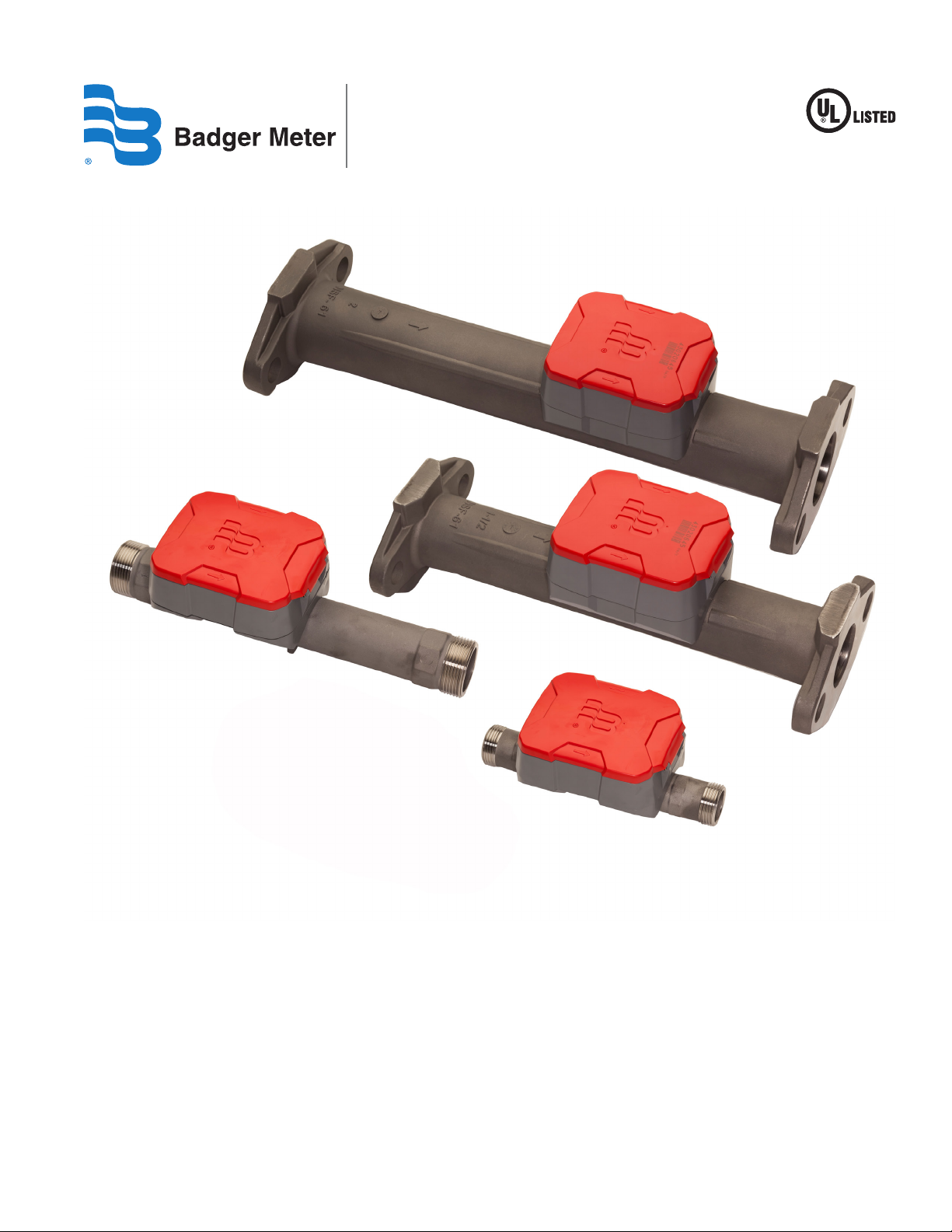
E-Series® Ultrasonic Meters
Cold Water Stainless Steel Meters for Fire Service Applications
ESM-UM-00624-EN-06 (August 2014)
User Manual
Page 2

E-Series® Ultrasonic Meters for Fire Service Applications
CONTENTS
About the E-Series Ultrasonic Meter . . . . . . . . . . . . . . . . . . . . . . . . . . . . . . . . . . . . . . . . . . . . . . . . . . . . . . . . . 3
Safety Information. . . . . . . . . . . . . . . . . . . . . . . . . . . . . . . . . . . . . . . . . . . . . . . . . . . . . . . . . . . . . . . . . . . . . 3
Product Unpacking and Inspection . . . . . . . . . . . . . . . . . . . . . . . . . . . . . . . . . . . . . . . . . . . . . . . . . . . . . . . . . . 3
Requirements. . . . . . . . . . . . . . . . . . . . . . . . . . . . . . . . . . . . . . . . . . . . . . . . . . . . . . . . . . . . . . . . . . . . . . . . 3
Reading Data Management Software. . . . . . . . . . . . . . . . . . . . . . . . . . . . . . . . . . . . . . . . . . . . . . . . . . . . . . 3
Mobile Reading Systems . . . . . . . . . . . . . . . . . . . . . . . . . . . . . . . . . . . . . . . . . . . . . . . . . . . . . . . . . . . . . . 3
Handheld Reading Systems . . . . . . . . . . . . . . . . . . . . . . . . . . . . . . . . . . . . . . . . . . . . . . . . . . . . . . . . . . . . 3
Meter Storage Mode . . . . . . . . . . . . . . . . . . . . . . . . . . . . . . . . . . . . . . . . . . . . . . . . . . . . . . . . . . . . . . . . . . . 4
Meter Pre-Installation . . . . . . . . . . . . . . . . . . . . . . . . . . . . . . . . . . . . . . . . . . . . . . . . . . . . . . . . . . . . . . . . . . 4
Special Instructions for removing a Meter . . . . . . . . . . . . . . . . . . . . . . . . . . . . . . . . . . . . . . . . . . . . . . . . . . . . . 5
Special Fittings and Accessories . . . . . . . . . . . . . . . . . . . . . . . . . . . . . . . . . . . . . . . . . . . . . . . . . . . . . . . . . . . . 5
Installing E-Series Ultrasonic Meters . . . . . . . . . . . . . . . . . . . . . . . . . . . . . . . . . . . . . . . . . . . . . . . . . . . . . . . . . 5
Outdoor Installations . . . . . . . . . . . . . . . . . . . . . . . . . . . . . . . . . . . . . . . . . . . . . . . . . . . . . . . . . . . . . . . . 5
Indoor Installations . . . . . . . . . . . . . . . . . . . . . . . . . . . . . . . . . . . . . . . . . . . . . . . . . . . . . . . . . . . . . . . . . 5
Installion Instructions . . . . . . . . . . . . . . . . . . . . . . . . . . . . . . . . . . . . . . . . . . . . . . . . . . . . . . . . . . . . . . . . 6
Protect Against Leakage . . . . . . . . . . . . . . . . . . . . . . . . . . . . . . . . . . . . . . . . . . . . . . . . . . . . . . . . . . . . . . 7
E-Series Ultrasonic Meter Operations . . . . . . . . . . . . . . . . . . . . . . . . . . . . . . . . . . . . . . . . . . . . . . . . . . . . . . . . . 7
Meter Display . . . . . . . . . . . . . . . . . . . . . . . . . . . . . . . . . . . . . . . . . . . . . . . . . . . . . . . . . . . . . . . . . . . . . 7
Activating the Display. . . . . . . . . . . . . . . . . . . . . . . . . . . . . . . . . . . . . . . . . . . . . . . . . . . . . . . . . . . . . . . . 7
Unit of Measure. . . . . . . . . . . . . . . . . . . . . . . . . . . . . . . . . . . . . . . . . . . . . . . . . . . . . . . . . . . . . . . . . . . . 7
Rate of Flow . . . . . . . . . . . . . . . . . . . . . . . . . . . . . . . . . . . . . . . . . . . . . . . . . . . . . . . . . . . . . . . . . . . . . . 8
Flow Direction . . . . . . . . . . . . . . . . . . . . . . . . . . . . . . . . . . . . . . . . . . . . . . . . . . . . . . . . . . . . . . . . . . . . 8
Consumption . . . . . . . . . . . . . . . . . . . . . . . . . . . . . . . . . . . . . . . . . . . . . . . . . . . . . . . . . . . . . . . . . . . . . 8
AMR/AMI Output. . . . . . . . . . . . . . . . . . . . . . . . . . . . . . . . . . . . . . . . . . . . . . . . . . . . . . . . . . . . . . . . . . . 9
Status Indicators . . . . . . . . . . . . . . . . . . . . . . . . . . . . . . . . . . . . . . . . . . . . . . . . . . . . . . . . . . . . . . . . . . . 9
Specications . . . . . . . . . . . . . . . . . . . . . . . . . . . . . . . . . . . . . . . . . . . . . . . . . . . . . . . . . . . . . . . . . . . . . . . 11
3/4" and 1" Meters . . . . . . . . . . . . . . . . . . . . . . . . . . . . . . . . . . . . . . . . . . . . . . . . . . . . . . . . . . . . . . . . . 11
1-1/2" and 2" Meters. . . . . . . . . . . . . . . . . . . . . . . . . . . . . . . . . . . . . . . . . . . . . . . . . . . . . . . . . . . . . . . . 12
Maintenance . . . . . . . . . . . . . . . . . . . . . . . . . . . . . . . . . . . . . . . . . . . . . . . . . . . . . . . . . . . . . . . . . . . . . . . 12
Page ii August 2014
Page 3

User Manual
ABOUT THE ESERIES ULTRASONIC METER
The Badger Meter E-Series® Ultrasonic meter is an electronic meter using ultrasonic technology and solid-state electronics
contained in a compact, totally encapsulated, weatherproof and UV-resistant housing for residential and commercial
applications. The ultrasonic measurement system has no moving parts, provides long-term accuracy and eliminates
measurement errors due to sand, suspended particles, air pockets and pressure fluctuations.
The Ultrasonic meter can be installed using horizontal or vertical piping, with water flow in the up direction. The meter will
not measure flow when an “empty pipe” condition is experienced. An empty pipe is defined as a condition when the flow
sensors are not fully submerged.
The Ultrasonic meter for fire service applications (sizes 3/4", 1", 1-1/2" and 2") is intended to comply with the requirements of
UL Subject 327B, inferential type water meters used in residential fire service applications. These applications are regulated by
local codes and requirements established by the Authority Having Jurisdiction (AHJ).
SAFETY INFORMATION
The installation of the E-Series Ultrasonic meter must comply with all applicable federal, state, and local rules, regulations,
and codes.
Failure to read and follow these instructions can lead to misapplication or misuse of the E-Series Ultrasonic meter, resulting in
personal injury and damage to equipment.
PRODUCT UNPACKING AND INSPECTION
Upon opening the shipping container, visually inspect the product and applicable accessories for any physical damage such
as scratches, loose or broken parts, or any other sign of damage that may have occurred during shipment.
OTE:N If damage is found, request an inspection by the carrier’s agent within 48 hours of delivery and file a claim with the
carrier. A claim for equipment damage in transit is the sole responsibility of the purchaser.
REQUIREMENTS
MPORTANTI
For proper handling of the higher reading resolution and the extended status indicator capabilities of the HR-E-Series Ultrasonic
meter, the following software versions are required for your reading system:
Reading Data Management Software
• ReadCenter Data: Version 1.11.12.27 or higher (does not include extended status indicator capabilities)
• ReadCenter Analytics and ReadCenter Analytics Mobile: Version 2.12.7.6 or later
• ReadCenter Analytics Pro and ReadCenter Analytics+: Version 1.0.0 or later
Mobile Reading Systems
• ORS: Version 2.2.1 or later
Handheld Reading Systems
• Badger Field Application Suite: Version 2.2.3 or later
• ORION Field Application route reading software: Version 2.2.3 or later
• ORION Endpoint Utility programming & quick read software: Version 2.2.2 or later
For assistance, please contact Badger Meter Technical Support at 1-800-876-3837 or the appropriate endpoint provider.
Page 3 August 2014
Page 4

E-Series® Ultrasonic Meters for Fire Service Applications
METER STORAGE MODE
All E-Series Ultrasonic meters are delivered in a storage mode so that a meter alarm is not triggered. During storage mode,
the empty pipe shows up on the LCD display as an error message, but it will not trigger a meter alarm. The meter needs to
sense a full pipe for 24 hours for the meter to go from storage mode to normal operation. If installed when the meter is still in
storage mode, the meter will function as expected with the addition of also displaying “err” on the flow rate screen. The meter
will display consumption and, if connected to AMR/AMI, will send a reading to the endpoint. When the meter is in normal
operation, the meter alarm displays immediately upon detecting the empty pipe condition. The alarm clears immediately
after the condition is corrected and the pipe is full. Systems that support the additional alarm conditions will be notified that
an empty pipe condition has occurred.
METER PREINSTALLATION
Take into account the following considerations before you begin an installation:
• Inspect the piping around the meter setting for suitable conditions. The service line, valves, connections and meter
must be watertight. Repair the piping system if pipes are corroded or damaged.
• Set the meter in a horizontal or vertical position with flow in the up direction. Registration should be upright and
protected from damage, freezing and tampering.
• Position the meter so it is accessible for installation, removal and reading.
• Verify that a suitable, electrical grounding wire is properly attached to the upstream and downstream pipe
connections of the meter. The grounding wire provides an alternative path for any electrical current that may exist
across the opening in the line.
• Close the curb (shutoff) valve to relieve water pressure in the line before starting the cutting operation. Provide a
high-quality upstream shutoff valve with a low pressure drop.
• When cutting into a new section of service pipe, flush the pipe to clear chips, pipe dope or other plumbing residue.
• For the 3/4" and 1" meters, the line opening in which the meter is to be set should match the laying length of the
meter, allowing slight additional space for coupling gaskets. The inlet and outlet sides of the meter setting should be
axially aligned to the pipe.
• For the 1-1/2" and 2" meters, the line opening in which the meter is to be set should match the laying length of the
meter. For optimal performance and accuracy, it is also recommended that a minimum of five diameters of straight
pipe be installed upstream of the meter.
• The installed meter must not be an obstacle or a hazard to the customer or interfere with public safety.
• DO NOT ATTEMPT TO USE ANY METER AS A LEVER OR CROWBAR TO STRAIGHTEN A MISALIGNED METER SETTING.
THIS COULD DAMAGE THE METER.
• DO NOT ATTEMPT TO SET A METER INTO AN OPENING THAT IS TOO LONG BY FORCING THE PIPING INTO PLACE
WITH THE METER'S COUPLING NUTS. THIS WILL CAUSE SERIOUS DAMAGE TO THE THREADED ENDS OF THE METER
AND HOUSING.
• TO AVOID POTENTIAL PROBLEMS, CORRECT ANY IRREGULARITIES IN PIPE SPACING AND MISALIGNMENT BEFORE
PLACING THE METER INTO ITS SETTING.
Page 4 August 2014
Page 5

User Manual
SPECIAL INSTRUCTIONS FOR REMOVING A METER
THE LINE MUST BE DEPRESSURIZED BEFORE STARTING ANY DISASSEMBLY OPERATION. REMOVING A METER THAT IS
UNDER LINE PRESSURE CAN RESULT IN COMPONENTS BECOMING PROJECTILES, CAPABLE OF CAUSING
PERSONAL INJURY.
SPECIAL FITTINGS AND ACCESSORIES
To accommodate installations for 3/4" and 1" meters, special fittings and accessories are available. Plastic swivel connections
are available from Badger Meter to compensate for minor service pipe and setting misalignment. Metal meter setters, resetters, horns and meter yokes are available for holding the service pipe in proper alignment to the meter and laying length
spacing. The metal setters and meter yokes can provide an electrical continuity to protect meters and consumers from
electrical shocks. Using a meter setter for the 1-1/2" and 2" is possible—however, be aware that the setter may affect the
accuracy of the meter.
INSTALLING ESERIES ULTRASONIC METERS
Outdoor Installations
When installed outdoors in a meter box, the E-Series Ultrasonic meter should have a two- to
three-inch clearance to avoid damage or strain to the service piping or meter, and to
accommodate any "settling" that may occur after installation.
The service pipe in the meter box should be properly bedded to ensure that it is not axially
misaligned and that it lays evenly on the bottom of the pipe trench. The backfill material covering
the pipe should be placed appropriately to maintain pipe alignment in the event of eventual
ground shifts. This will prevent damage to the pipe.
The service lines and the water meter must be protected from freezing. The earth covering the service line must be adequate
to prevent frost penetration. Due to the smaller volume of water, service line pipes will freeze sooner than the main
distribution line.
The meter box pit should be excavated below the frost line. Even though the meter itself may be positioned above the frost
line, the warmer air rising from the earth below the frost line will reduce the possibility of freezing.
Indoor Installations
As a precautionary measure when working with metallic pipes, indoor settings must be checked
for electrical continuity through the service pipe before you remove or service a meter. American
Water Works Association (AWWA) policy specifies that service pipes must not be used as an
electrical ground. Check your local codes and practices. A permanent ground strap or metal setter
must be used if electrical grounding to water services is required in your community.
To prevent floor damage, close the valve downstream from the meter before installing or removing a meter.
Page 5 August 2014
Page 6

E-Series® Ultrasonic Meters for Fire Service Applications
Installion Instructions
To prepare for meter installation, follow these steps:
1. Close the meter's inlet-side valve.
2. Open a faucet and wait until water ow stops, to depressurize the system. Do not remove the meter until the
ow stops.
3. Check valves and make necessary repairs to the curb (shuto) valve or inlet side valve if necessary.
4. Before installing or removing a meter, close the outlet-side valve to relieve pressure. Protect the area around the meter
against potential spills or leaks that could occur.
5. To replace an existing meter continue with Step 6. To install a new meter skip to Step 8.
6. Loosen the meter couplings or ange bolts and remove the meter and the old gaskets in the coupling nuts. You may
choose to replace the old gaskets with the provided 9/64" thick rubber gaskets.
7. Clean the coupling nuts or ange bolts, removing any pipe dope or dirt from the threads or ange bolts.
8. Check the existing setting for proper alignment and spacing. Correct any misalignment and spacing in the setting.
9. Place the connection gaskets inside the connection coupling nuts.
10. Set the meter between the coupling nuts or in the ange pipeline, positioned so that the ow arrow on the meter housing
points in the direction of ow. Registration should be upright.
11. For 3/4" to 1" Straight
a. Start the coupling nuts at the threaded meter ends. Verify that the nuts are properly aligned to avoid cross-threading
or damage to the meter ends.
b. An eective method for starting a coupling nut is:
i. Position the nut squarely against the meter's spud end.
ii. Turn the nut counterclockwise (in reverse) while holding the nut against the meter spud end. When the first
threads on both the nut and the spud end coincide, you will hear a slight click and feel the nut move into the
starting position.
iii. Tighten the nut by hand until it is "hand-tight".
iv. With an open-end wrench, apply a partial turn. Do not over tighten. For plastic swivel connections, a one-quarter
turn beyond hand-tight is usually sufficient.
11. For 1-1/2" to 2" Elliptical Flange Ends
a. With meter and gaskets in place, tighten the ange connection bolts. Verify the nuts are properly aligned to avoid
damage to the anged ends.
12. After the meter is installed, open the inlet shuto valve until the meter is full of water and ensure that there are no leaks.
(The more ow you allow through the meter, appropriate for the meter size, the better.)
13. Open the outlet valve until air is out of the meter and service line.
14. Open a valve downstream of the meter and verify that no foreign debris in the water obstructs the operations of
the system.
15. Make sure the meter is installed with the ow arrow on the meter pointing in the direction of ow. Check the read on the
meter to make sure it is registering a positive number. If it is not, make sure the meter is installed in the correct direction.
a. The meter is sent in Storage mode so that customers do not experience alarms during shipment or installation. In
general, a meter may take up to 2 minutes to begin measurement once the meter senses a full pipe.
b. The meter itself does not require a quantity of ow to begin measurement, the meter just requires that the pipe is
cleared of air and lled with water. If the customer is attempting to purge the meter at low ow rates, it would likely be
more dicult and take longer.
16. When the meter starts recording positive ow, note the meter read for your records.
Page 6 August 2014
Page 7

User Manual
Protect Against Leakage
Before turning on the service water, use care to protect against potential leakage.
1. Shut o the valves on both the inlet and outlet sides of the meter.
2. Open the curb (shuto) valve slowly to pressurize the service line to the meter.
3. Slowly open the meter's inlet-side valve to ll the meter.
4. Check for leaks around the meter and its connections.
5. Slowly open the meter's outlet-side valve to pressurize the consumer side of the system.
6. Open a faucet to allow entrapped air to escape.
7. Once water is owing normally, turn o the faucet.
ESERIES ULTRASONIC METER OPERATIONS
Meter Display
The Badger Meter E-Series Ultrasonic meters use a nine-digit Liquid Crystal Display (LCD) to show consumption, flow and
alarm information. See Status Indicators chart on page 10 for detailed descriptions.
Lines Indicating Typical
Billing Segments
Flow Rate
Unit of Measure
Status Indicators
Activating the Display
The Ultrasonic meter's display illuminates when the register cover is opened. After a period of time, the display will revert to
sleep mode. You can alternate the display between total flow and rate of flow mode by touching the optical display switch or
by closing and opening the meter's lid. The optical switch is located just below the LCD on the left side of the register's face.
Optical
Switch
Unit of Measure
The unit of measure and resolution are factory programmed and options include gallons, cubic feet and cubic meters.
For 3/4" through 1" meters, totalized flow displays up to 10 million gallons with a resolution of 0.01 gallons, one million cubic
feet with a resolution of 0.001 cubic feet, or 100 thousand cubic meters with a resolution of 0.0001 cubic meters.
For the 1-1/2" and 2" meters, totalized flow displays up to 100 million gallons with a resolution of 0.1 gallons, 10 million cubic
feet with a resolution of 0.01 cubic feet, or one million cubic meters with a resolution of 0.001.
Page 7 August 2014
Page 8

E-Series® Ultrasonic Meters for Fire Service Applications
Rate of Flow
The rate of flow is factory programmed for gallons per minute and meters cubes per hour, depending on the unit of
measure selected. The LCD displays both the unit of measure and rate of flow. The rate of flow display also serves as the flow
finder indicator. The rate of flow display is shown without leading zeros. When rate of flow is displayed it is updated every
two seconds.
Flow Direction
The direction of water flow is noted on the face of the electronics housing and cast into the meter housing.
Consumption
The consumption display includes all nine digits, including leading zeroes and a decimal point. The displayed value is the sum
of the forward flow minus the reverse flow. This display also includes indicator lines above and below the digits to provide
the electronic equivalent of white and black number wheels on mechanical registers. The following examples show typical
displays for three different units of measure:
3/4" and 1" Meters 1-1/2" and 2" Meters
Gallons
1 2 3 4 5 6 7. 8 9 1 2 3 4 5 6 7 8. 9
• Visual reading for typical consumption/billing
purposes: 1234 thousands of gallons.
• Detailed meter reading with full display resolution:
1234567.89 gallons.
Cubic Feet
• Visual reading for typical consumption/billing
purposes: 12345 thousands of gallons.
• Detailed meter reading with full display resolution:
12345678.9 gallons.
1 2 3 4 5 6. 7 8 9 1 2 3 4 5 6 7. 8 9
• Visual reading for typical consumption/billing
purposes: 1234 hundreds of cubic feet.
• Detailed meter reading with full display resolution:
123456.789 cubic feet.
Cubic Meters
• Visual reading for typical consumption/billing
purposes: 12345 hundreds of cubic feet.
• Detailed meter reading with full display resolution:
1234567.89 cubic feet.
1 2 3 4 5. 6 7 8 9 1 2 3 4 5 6. 7 8 9
• Visual reading for typical consumption/billing
purposes: 1234 cubic meters.
• Visual reading for typical consumption/billing
purposes: 12345 cubic meters.
• Detailed meter reading with full display resolution:
12345.6789 cubic meters.
Page 8 August 2014
• Detailed meter reading with full display resolution:
123456.789 cubic meters.
Page 9

User Manual
AMR/AMI Output
The Ultrasonic meter is an integrated design where the electronics are housed, fully potted, and permanently sealed to the
meter housing.
Programmed to the high resolution industry standard ASCII encoder protocol, the Ultrasonic meters have the ability to
transmit meter status indicators to ORION Cellular, Fixed Network (SE) and Migratable (ME) endpoints as part of the extended
encoder/meter reading message. The details can also be read through an IR interface. The output protocol is indicated on the
AMR output wire and is determined at the time of order.
The Ultrasonic meter is available with a wired lead, in-line connector, or fully prewired to AMR/AMI devices.
Endpoint Reading Resolution
The reading resolution sent to the reading software is dependent on the endpoint to which the Ultrasonic meter is connected.
Readings reported from the endpoints are the left-most significant digits of the LCD reading.
Technology High Res E-Series ADE E-Series ADE * E-Series RTR *
ORION Cellular 9 digit reading 6 digit reading —
ORION Fixed Network (SE) 8 digit reading 6 digit reading 7 digit reading
ORION Migratable (ME) 8 digit reading 6 digit reading 7 digit reading
ORION Classic (CE) 7 digit reading 6 digit reading 7 digit reading
GALAXY 6 digit reading 6 digit reading 7 digit reading
Itron 100W 8/9 digit reading ** 6 digit reading 7 digit reading
Itron 100W + 9 digit reading 6 digit reading 7 digit reading
* No longer for sale.
** 100W will transmit 9 digits through Itron's xed network, but will truncate to the 8 left-most signicant digits for standard mobile and handheld readings.
Status Indicators
Indicators and alarms appear in the display as symbols that illuminate when the condition is active and dim when the alarm
condition is eliminated.
All E-Series Ultrasonic meters are delivered in a storage mode so that a meter alarm is not triggered. During storage mode,
the empty pipe shows up on the LCD display as an error message, but it will not trigger a meter alarm. The meter needs to
sense a full pipe for 24 hours for the meter to go from storage mode to normal operation. If installed when the meter is still in
storage mode, the meter will function as expected with the addition of also displaying “err” on the flow rate screen. The meter
will display consumption and, if connected to AMR/AMI, will send a reading to the endpoint. When the meter is in normal
operation, the meter alarm displays immediately upon detecting the empty pipe condition. The alarm clears immediately
after the condition is corrected and the pipe is full. Systems that support the additional alarm conditions will be notified that
an empty pipe condition has occurred.
For the High Resolution E-Series Ultrasonic meter, ORION Fixed/Migratable (SE/ME) endpoint firmware version 1.8 or higher
is required.
The following chart indicates the E-Series Ultrasonic meter conditions when connected to Badger Meter ORION Cellular
and Fixed/Migratable (SE/ME) AMR/AMI endpoints.
The chart does not apply to ORION Classic (CE) or GALAXY endpoints. The E-Series will display the indicators, but Reverse
Flow, Suspected Leak and 30 Day No Usage alarms are determined by the endpoint radio and are not obtained from the
Ultrasonic meter.
Page 9 August 2014
Page 10

E-Series® Ultrasonic Meters for Fire Service Applications
Status
Indicator
Meter
Icon Alarm Description
Meter operating correctly. Normal operation.
functioning
correctly
Meter alarm Several potential conditions may
exist, including:
• Empty pipe: “err” displays on
LCD. Alarm clears when pipe
is filled.
• Low Temperature limits
exceeded: meter continues to
operate but outside specified
accuracy range. Alarm clears
after 35 days unless alarm
condition continues.
• Maximum flow rate is exceeded.
No consumption is displayed
until back within specified
flow range. Both the meter
functioning correctly and the
meter alarm are active.
• Other meter or sensor issue:
meter continues to operate if
possible. Alarm clears after
35 days unless alarm
condition continues.
Reverse flow The meter detects reverse flow
and triggers the reverse flow alarm
icon on the E-Series display. The
alarm remains active for 35 days.
The alarm automatically clears
after 35 days if the condition has
not recurred.
Suspected
leak
Meter detects 24 hours without
one 15-minute interval of no ow.
The alarm clears automatically
when a 15-minute no-ow
interval occurs.
30 day no
usage
No measured flow in past 30 days.
The alarm automatically clears
once flow occurs.
End of life
battery
indicator
Indicated battery life based on precalculated consumption. Alarm
is activated after 19 years and 6
months and does not clear.
High Resolution
with ORION
Cellular, Fixed
Network (SE) or
Migratable (ME)
Indicator not sent
to endpoint.
Consumption
data is sent to the
endpoint. Meter
Alarm is also sent.
Meter detects
reverse flow
and sends alarm
message to
the endpoint.
Meter detects
suspected leak
and sends alarm
message to
the endpoint.
Meter detects 30
day no usage and
sends alarm to
the endpoint.
Meter sends alarm
to the endpoint.
Encoder Protocol
with ORION
Cellular, Fixed
Network (SE) or
Migratable (ME)
Normal operation.
Indicator not sent
to endpoint.
Meter Alarm is sent
to the endpoint.
NOTE: No
consumption data
is sent to endpoint
when the alarm
RTR with
ORION Fixed
Network (SE) or
Migratable (ME)
Normal operation.
Indicator not sent to
endpoint.
Consumption
data is sent to the
endpoint, except
when Exceeding
Max Flow Alarm
is set.
is active.
Meter does not
send the alarm. The
endpoint detects
and reports the
reverse flow and
No alarm condition
reported by the
endpoint will only
record positive,
forward flow.
will report the
read exactly how it
is received.
Meter does not send the alarm.
The endpoint detects continuous
consumption over 24-hour period and
reports suspected leak.
Meter does not send the alarm.
The endpoint detects no change in
consumption over 30-day period and
reports 30 day no usage.
Meter does not send the alarm.
Page 10 August 2014
Page 11

SPECIFICATIONS
3/4" and 1" Meters
E-Series Ultrasonic | Residential
Fire Service
Certified under UL 327B Residential Fire
Service Meters – File No. 15653,
Control No. 4DP3
Operating Range
(per UL Listing, at ±1.5% accuracy)
Operating Range 0.1…32 gpm 0.4…55 gpm
Extended Low-Flow Rate 0.05 gpm 0.25 gpm
Maximum Continuous Operation 32 gpm 55 gpm
Pressure Loss 2.0 psi at 15 gpm 1.8 psi at 25 gpm
Reverse Flow - Maximum Rate 4.0 gpm 9.0 gpm
In the normal temperature range of 45…85° F (7…29° C), new meter
Operating Performance
Storage Temperature – 40…140° F (– 40…60° C)
Maximum Ambient Storage
(Storage for One Hour)
Measured-Fluid Temperature Range 34…140° F (1…60° C)
Humidity 0…100% condensing
Maximum Operating Pressure of
Meter Housing
Register Type
Register Display
Register Capacity
Totalization Display Resolution
Battery
consumption measurement is accurate to:
• ±1.5% over the normal flow range
• ±3.0% from the extended low flow range to the minimum flow value
150° F (72° C)
175 psi (12 bar)
Straight reading, permanently sealed electronic LCD; digits are
0.28" (7 mm) high
• Consumption (up to nine digits)
• Rate of flow
• Alarms
• Unit of measure factory programmed for gallons, cubic feet and cubic meters
• 10,000,000 gallons
• 1,000,000 cubic feet
• 100,000 cubic meters
• Gallons: 0.XX
• Cubic feet: 0.XXX
• Cubic meters: 0.XXXX
3.6-volt lithium thionyl chloride; battery is fully encapsulated within the register
housing and is not replaceable; 20-year battery life
3/4" (20 mm) 1" (25 mm)
2…30 gpm 2…50 gpm
User Manual
Page 11 August 2014
Page 12

E-Series® Ultrasonic Meters for Fire Service Applications
1-1/2" and 2" Meters
E-Series Ultrasonic | Residential
Fire Service
Certified under UL 327B Residential Fire
Service Meters – File No. 15653,
Control No. 4DP3
Operating Range 1.5…100 gpm 2…160 gpm
Extended Low-Flow Rate 0.40 gpm 0.50 gpm
Maximum Continuous Operation 100 gpm 160 gpm
Pressure Loss at Maximum Flow 3.8 psi 4.7 psi
Reverse Flow - Maximum Rate 12 gpm 18 gpm
Operating Performance
Storage Temperature – 40…140° F (– 40…60° C)
Maximum Ambient Storage
(Storage for One Hour)
Measured-Fluid Temperature Range 34…140° F (1…60° C)
Humidity 0…100% condensing
Maximum Operating Pressure of
Meter Housing
Register Type
Register Display
Register Capacity
Totalization Display Resolution
Battery
1-1/2" (40 mm) 2" (50 mm)
In the normal temperature range of 45…85° F (7…29° C), new meter
consumption measurement is accurate to:
• ±1.5% over the normal flow range
• ±3.0% from the extended low flow range to the minimum flow value
150° F (72° C)
175 psi (12 bar)
Straight reading, permanently sealed electronic LCD; digits are
0.28" (7 mm) high
• Consumption (up to nine digits)
• Rate of flow
• Alarms
• Unit of measure factory programmed for gallons, cubic feet and cubic meters
• 100,000,000 gallons
• 10,000,000 cubic feet
• 1,000,000 cubic meters
• Gallons: 0.X
• Cubic feet: 0.XX
• Cubic meters: 0.XXX
3.6-volt lithium thionyl chloride; battery is fully encapsulated within the register
housing and is not replaceable; 20-year battery life
MAINTENANCE
The Badger Meter E-Series Ultrasonic meters are designed and manufactured to provide long-term service with no
maintenance. The enclosure, which includes the electronic meter’s ultrasonic sensors, battery and display, is completely
potted, permanently sealed, and non-removable.
Making Water Visible®
ADE, E-Series, GALAXY, Making Water Visible, ORION, Recordall and RTR are registered trademarks of Badger Meter, Inc. Other trademarks appearing in this document are the
property of their respective entities. Due to continuous research, product improvements and enhancements, Badger Meter reserves the right to change product or system
specications without notice, except to the extent an outstanding contractual obligation exists. © 2014 Badger Meter, Inc. All rights reserved.
www.badgermeter.com
The Americas | Badger Meter | 4545 West Brown Deer Rd | PO Box 245036 | Milwaukee, WI 53224-9536 | 800-876-3837 | 414-355-0400
México | Badger Meter de las Americas, S.A. de C.V. | Pedro Luis Ogazón N°32 | Esq. Angelina N°24 | Colonia Guadalupe Inn | CP 01050 | México, DF | México | +52-55-5662-0882
Europe, Middle East and Africa | Badger Meter Europa GmbH | Nurtinger Str 76 | 72639 Neuen | Germany | +49-7025-9208-0
Europe, Middle East Branch Oce | Badger Meter Europe | PO Box 341442 | Dubai Silicon Oasis, Head Quarter Building, Wing C, Oce #C209 | Dubai / UAE | +971-4-371 2503
Czech Republic | Badger Meter Czech Republic s.r.o. | Maříkova 2082/26 | 621 00 Brno, Czech Republic | +420-5-41420411
Slovakia | Badger Meter Slovakia s.r.o. | Racianska 109/B | 831 02 Bratislava, Slovakia | +421-2-44 63 83 01
Asia Pacic | Badger Meter | 80 Marine Parade Rd | 21-06 Parkway Parade | Singapore 449269 | +65-63464836
China | Badger Meter | 7-1202 | 99 Hangzhong Road | Minhang District | Shanghai | China 201101 | +86-21-5763 5412 Legacy Document Number: ESM-IOM-02-EN
 Loading...