

Page 1
Display
ER-500 Advanced
DSY-PM-00028-EN-02 (February 2017)
Programming Manual
Page 2

ER-500 Flow Monitor
Page ii February 2017DSY-PM-00028-EN-02
Page 3

Programming Manual
CONTENTS
Scope of This Manual . . . . . . . . . . . . . . . . . . . . . . . . . . . . . . . . . . . . . . . . . . . . . . . . . . . . . . . . . . . . . . . . . . . 5
Unpacking and Inspection . . . . . . . . . . . . . . . . . . . . . . . . . . . . . . . . . . . . . . . . . . . . . . . . . . . . . . . . . . . . . . . 5
Safety . . . . . . . . . . . . . . . . . . . . . . . . . . . . . . . . . . . . . . . . . . . . . . . . . . . . . . . . . . . . . . . . . . . . . . . . . . . . . 5
Terminology and Symbols . . . . . . . . . . . . . . . . . . . . . . . . . . . . . . . . . . . . . . . . . . . . . . . . . . . . . . . . . . . . . 5
Considerations . . . . . . . . . . . . . . . . . . . . . . . . . . . . . . . . . . . . . . . . . . . . . . . . . . . . . . . . . . . . . . . . . . . . 5
Electrical Symbols . . . . . . . . . . . . . . . . . . . . . . . . . . . . . . . . . . . . . . . . . . . . . . . . . . . . . . . . . . . . . . . . . . 5
Introduction. . . . . . . . . . . . . . . . . . . . . . . . . . . . . . . . . . . . . . . . . . . . . . . . . . . . . . . . . . . . . . . . . . . . . . . . . 6
Installation. . . . . . . . . . . . . . . . . . . . . . . . . . . . . . . . . . . . . . . . . . . . . . . . . . . . . . . . . . . . . . . . . . . . . . . . . . 7
Connecting the ER-500 Monitor to a Pulse Output Device. . . . . . . . . . . . . . . . . . . . . . . . . . . . . . . . . . . . . . . . . 7
Transmitter Connections . . . . . . . . . . . . . . . . . . . . . . . . . . . . . . . . . . . . . . . . . . . . . . . . . . . . . . . . . . . . . . 7
Power Connections . . . . . . . . . . . . . . . . . . . . . . . . . . . . . . . . . . . . . . . . . . . . . . . . . . . . . . . . . . . . . . . . . 8
Operating The Monitor . . . . . . . . . . . . . . . . . . . . . . . . . . . . . . . . . . . . . . . . . . . . . . . . . . . . . . . . . . . . . . . . . . 9
Buttons . . . . . . . . . . . . . . . . . . . . . . . . . . . . . . . . . . . . . . . . . . . . . . . . . . . . . . . . . . . . . . . . . . . . . . . . . 9
Special Functions . . . . . . . . . . . . . . . . . . . . . . . . . . . . . . . . . . . . . . . . . . . . . . . . . . . . . . . . . . . . . . . . . . 9
Modes. . . . . . . . . . . . . . . . . . . . . . . . . . . . . . . . . . . . . . . . . . . . . . . . . . . . . . . . . . . . . . . . . . . . . . . . . . 9
Programming Using Frequency Output Flow Sensors . . . . . . . . . . . . . . . . . . . . . . . . . . . . . . . . . . . . . . . . . . . 9
Menu Structure. . . . . . . . . . . . . . . . . . . . . . . . . . . . . . . . . . . . . . . . . . . . . . . . . . . . . . . . . . . . . . . . . . . . . . 10
Standard ER-500, Rate SU is Set to Simple . . . . . . . . . . . . . . . . . . . . . . . . . . . . . . . . . . . . . . . . . . . . . . . . . . 10
Advanced ER-500, Basic Menu . . . . . . . . . . . . . . . . . . . . . . . . . . . . . . . . . . . . . . . . . . . . . . . . . . . . . . . . . 11
Standard ER-500, Rate SU is Set to Advanced . . . . . . . . . . . . . . . . . . . . . . . . . . . . . . . . . . . . . . . . . . . . . . . . 12
Advanced ER-500, Advanced Menu . . . . . . . . . . . . . . . . . . . . . . . . . . . . . . . . . . . . . . . . . . . . . . . . . . . . . . 14
Programming. . . . . . . . . . . . . . . . . . . . . . . . . . . . . . . . . . . . . . . . . . . . . . . . . . . . . . . . . . . . . . . . . . . . . . . 16
Parameters. . . . . . . . . . . . . . . . . . . . . . . . . . . . . . . . . . . . . . . . . . . . . . . . . . . . . . . . . . . . . . . . . . . . . . 16
K-factors Explained . . . . . . . . . . . . . . . . . . . . . . . . . . . . . . . . . . . . . . . . . . . . . . . . . . . . . . . . . . . . . . . . . . . 25
Modbus Interface . . . . . . . . . . . . . . . . . . . . . . . . . . . . . . . . . . . . . . . . . . . . . . . . . . . . . . . . . . . . . . . . . . . . 27
Modbus Register / Word Ordering . . . . . . . . . . . . . . . . . . . . . . . . . . . . . . . . . . . . . . . . . . . . . . . . . . . . . . . 27
Register Mappings. . . . . . . . . . . . . . . . . . . . . . . . . . . . . . . . . . . . . . . . . . . . . . . . . . . . . . . . . . . . . . . . . 27
Battery Replacement . . . . . . . . . . . . . . . . . . . . . . . . . . . . . . . . . . . . . . . . . . . . . . . . . . . . . . . . . . . . . . . . . . 29
Specications. . . . . . . . . . . . . . . . . . . . . . . . . . . . . . . . . . . . . . . . . . . . . . . . . . . . . . . . . . . . . . . . . . . . . . . 30
Model Numbers . . . . . . . . . . . . . . . . . . . . . . . . . . . . . . . . . . . . . . . . . . . . . . . . . . . . . . . . . . . . . . . . . . . . . 31
Dimensions . . . . . . . . . . . . . . . . . . . . . . . . . . . . . . . . . . . . . . . . . . . . . . . . . . . . . . . . . . . . . . . . . . . . . . . . 31
Troubleshooting Guide. . . . . . . . . . . . . . . . . . . . . . . . . . . . . . . . . . . . . . . . . . . . . . . . . . . . . . . . . . . . . . . . . 31
Control Drawing . . . . . . . . . . . . . . . . . . . . . . . . . . . . . . . . . . . . . . . . . . . . . . . . . . . . . . . . . . . . . . . . . . . . . 32
Page iii February 2017 DSY-PM-00028-EN-02
Page 4

ER-500 Flow Monitor
Page iv February 2017DSY-PM-00028-EN-02
Page 5
Scope of This Manual
SCOPE OF THIS MANUAL
This manual is intended to help you get the ER-500 flow monitor up and running quickly.
MPORTANTI
Read this manual carefully before attempting any installation or operation. Keep the manual accessible for future reference.
UNPACKING AND INSPECTION
Upon opening the shipping container, visually inspect the product and applicable accessories for any physical damage such
as scratches, loose or broken parts, or any other sign of damage that may have occurred during shipment.
OTE:N If damage is found, request an inspection by the carrier’s agent within 48 hours of delivery and file a claim with the
carrier. A claim for equipment damage in transit is the sole responsibility of the purchaser.
SAFETY
Terminology and Symbols
Indicates a hazardous situation, which, if not avoided, is estimated to be capable of causing death or
serious personal injury.
Indicates a hazardous situation, which, if not avoided, could result in severe personal injury or death.
Indicates a hazardous situation, which, if not avoided, is estimated to be capable of causing minor or
moderate personal injury or damage to property.
Considerations
The installation of the ER-500 flow monitor must comply with all applicable federal, state, and local rules, regulations,
and codes.
WARNING
EXPLOSION HAZARD - SUBSTITUTION OF COMPONENTS MAY IMPAIR SUITABILITY FOR CLASS I, DIVISION 2.
AVERTISSMENT
RISQUE D’EXPLOSION - LA SUBSTITUTION DE COMPOSANTS PEUT RENDRE CEMATÉRIEL INACCCEPTABLE POUR LES
EMPLACEMENTS DE CLASSE I, DIVISION 2.
WARNING
DO NOT CONNECT OR DISCONNECT EITHER POWER OR OUTPUTS UNLESS THE AREA IS KNOWN TO BE
NON-HAZARDOUS.
AVERTISSMENT
RISQUE D’EXPLOSION. NE PAS DÉBRANCHER TANT QUE LE CIRCUIT EST SOUSTENSION, À MOINS QU’LL NE S’AGISSE
D’UN EMPLACEMENT NON DANGEREUX.
MPORTANTI
Not following instructions properly may impair safety of equipment and/or personnel.
Electrical Symbols
Function Direct Current Alternating Current Earth (Ground) Protective Ground Chassis Ground
Symbol
DSY-PM-00028-EN-02 Page 5 February 2017
Page 6
Introduction
INTRODUCTION
The ER-500 flow monitor incorporates state-of-the-art digital signal processing technology designed to provide the user with
exceptional flexibility at a very affordable price. Though designed for use with Badger Meter® flow sensors, this monitor can
be used with almost any flow sensor producing a low amplitude AC output or contact closure signal.
The ER-500 monitor uses contact closures from an ILR transmitter that translates to flow rate through the use of a scaling
constant called a K-factor.
This monitor is also capable of accepting low-level frequency input signals typically found in flow sensors that generate
a frequency output. The output signal for these type of sensors is a frequency proportional to the rate of flow. The ER-500
monitor uses the frequency information to calculate flow rate and total flow. If required, the flow monitor can easily be
re-configured in the field.
J1
KB/Display
P2
+ –
RS485 Gnd
Setpoint 1
Setpoint 2
Iso Total Pluse
Total Reset
OC Total Pluse
Signal Gnd
Freq. In
4-20mA
TR_B
TR_A
Gnd
P1
2
1
+
–
+
–
+
–
JP1
Input Total Pulse Signal
Pulse
Mag
JP2
OC
Iso
JP3
High
Low
TB1
Figure 1: ER-500 monitor
The monitor is available in two different levels of functionality. The standard model provides all the functions necessary for
the most common flow metering applications. The advanced version adds communications capabilities over an RS485 bus
using Modbus RTU and control outputs.
DSY-PM-00028-EN-02Page 6 February 2017
Page 7
(Should be set to Low for IOG Meter)
Auxiliary Reed
Installation
INSTALLATION
Connecting the ER-500 Monitor to a Pulse Output Device
The ER-500 monitor has two jumpers that are used to set the type of signal and the minimum amplitude of the signal that
it accepts. When used with Badger Meter IOG oval gear meters, the Input Signal Level should be set to Low and the Input
Waveform should be set for pulse as shown in Figure 2.
JP1
Pulse
Mag
OC
Iso
High
Low
Input Total Pulse Signal
Input Waveform Selection
(Should be set to Pulse for IOG meter)
JP2
JP3
Input Signal Level Selection
Figure 2: Input jumper settings
If the ER-500 monitor is a replacement, it must be calibrated for the IOG it is intended to be used with. The K-factor for the
specific IOG meter must be programmed into the ER-500 monitor. The K-factor value is found on the calibration certificate
that came with the IOG meter. For instructions on programming the K-factor, see Enter Flow Sensor's K-factor* on page 17.
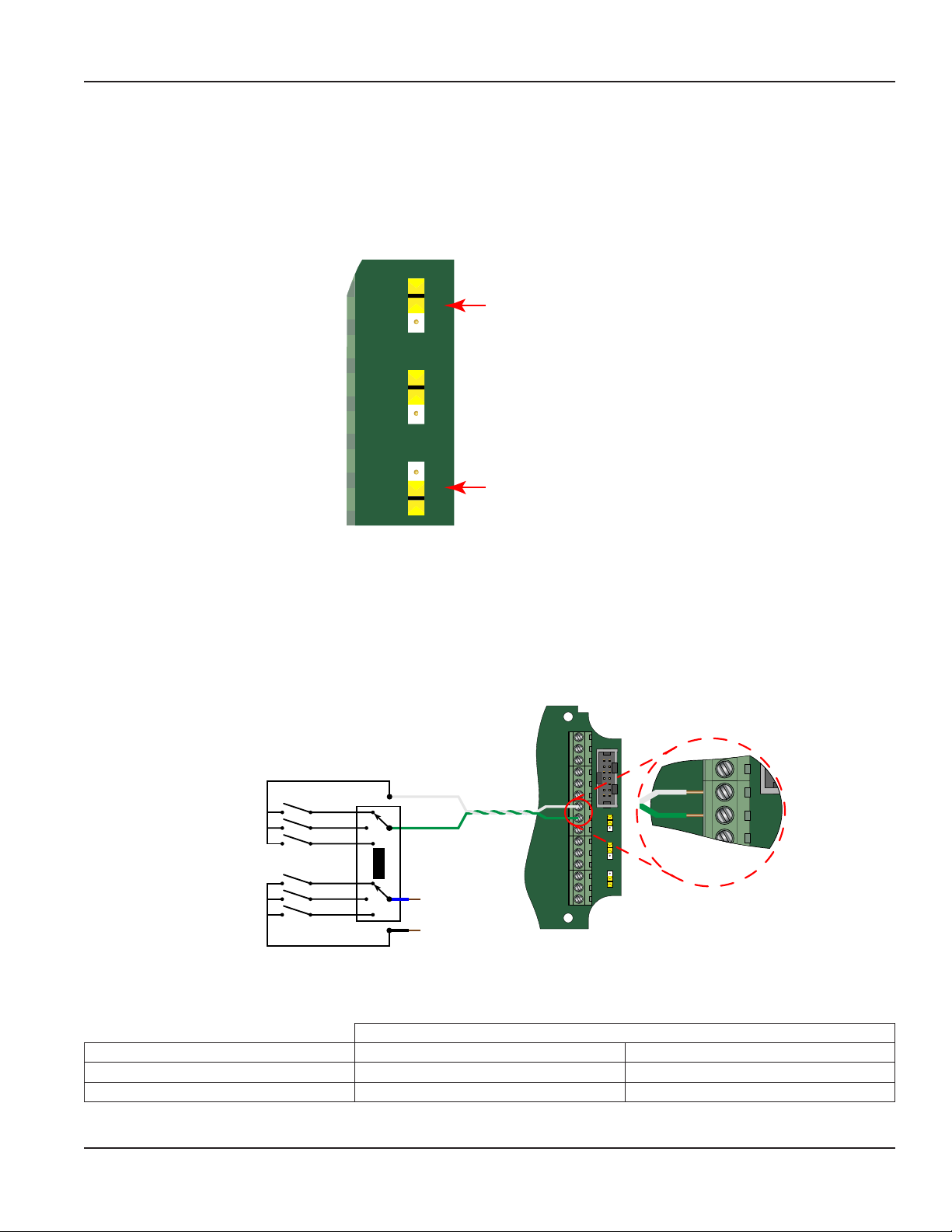
Transmitter Connections
The ILR transmitter typically used with the IOG meter family has two sets of pulse output wires. The white and green output
leads connected to the primary reed switch bank are generally the first choice (see Figure 3).
TR_B
RS485 Gnd
Setpoint 1
Setpoint 2
Iso Total Pluse
Total Reset
OC Total Pluse
Signal Gnd
TR_A
Freq. In
4-20mA
Reed Switch
Bank
Switch Bank
ILR
Pulse Transmitter
White
Green
Blue
Black
Figure 3: Typical IOG meter input connection
The ILR transmitter also has a secondary (auxiliary) set of pulse output wires. Either pair can be used to connect to the ER-500
monitor. The connections are:
P1
Gnd
Gnd
+
JP1
Input Total Pulse Signal
Pulse
–
Mag
+
JP2
–
OC
+
Iso
–
JP3
High
Low
TB1
Freq. In
+
–
Pulse
Mag
ILR Wires
ER-500 Terminals Reed Switch Bank (Primary) Reed Switch Bank (Auxiliary)
Freq. In + White Blue
Freq. In - Green Black
DSY-PM-00028-EN-02 Page 7 February 2017
Page 8
10
Installation
Power Connections
The ER-500 monitor has two power supply options. The first power supply is an internal lithium 3.6V DC D size cell that powers
the monitor for about six years when no outputs are used. The monitor can also be powered by a 4…20 mA current loop.
See Figure 4. If the current loop is used, a sensing circuit within the monitor detects the presence of the current loop and
automatically disconnects the battery from the circuit.
TR_B
Pulse
Mag
OC
Iso
High
Low
P1
JP1
Input Total Pulse Signal
JP2
JP3
…28V DC
4-20 mA
Current Loop
(10 …28V DC)
Load
RS485 Gnd
Setpoint 1
Setpoint 2
Freq. In
4-20mA
Iso Total Pluse
Total Reset
OC Total Pluse
Signal Gnd
TR_A
Gnd
+
–
+
–
+
–
TB1
Figure 4: Loop power connections
DSY-PM-00028-EN-02Page 8 February 2017
Page 9

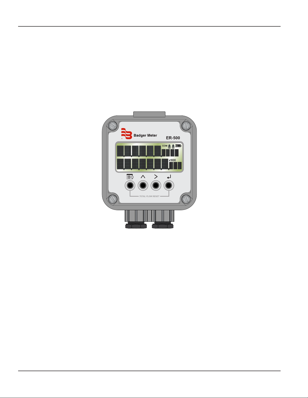
OPERATING THE MONITOR
Figure 5: Keypad detail
Buttons
MENU Switches between RUN and PROGRAMMING modes
Operating The Monitor
2
1
Scrolls backwards through the parameter options, increments numeric variables and scrolls backward through
UP
parameters
RIGHT
ENTER Saves programming information, advances to the next programming parameter, and used in the reset process
Scrolls forward through the parameter options, moves the active digit to the right and scrolls forward through
parameters
Special Functions
MENU + ENTER Simultaneously press and hold to reset the current totalizer
MENU Press and hold for three seconds to enter Extended Programming mode
UP+ RIGHT Simultaneously press and hold to show the firmware version number, then the grand total
Modes
RUN Normal operating mode
PROGRAM Used to program parameters in the display
EXTENDED PROGRAMMING Used to program advanced variables into the display
TEST Used as a diagnostic tool to show input frequency and totalizer counts
If the monitor is a replacement, the K-factor of the flow sensor has changed, or the monitor is being used with some other
pulse generating device, programming is necessary.
Programming Using Frequency Output Flow Sensors
Each Badger Meter flow sensor is shipped with either a K-factor value or frequency data. If frequency data is provided, the
data must be converted to a K-factor before programming the monitor. The K-factor represents the number of pulses per
unit of volume. See Connecting the ER-500 Monitor to a Pulse Output Device on page 7. The K-factor is needed to program
the monitor.
DSY-PM-00028-EN-02 Page 9 February 2017
Page 10
Rate SU
(Rate Unit Setup)
Simple Advanced
Menu Structure
MENU STRUCTURE
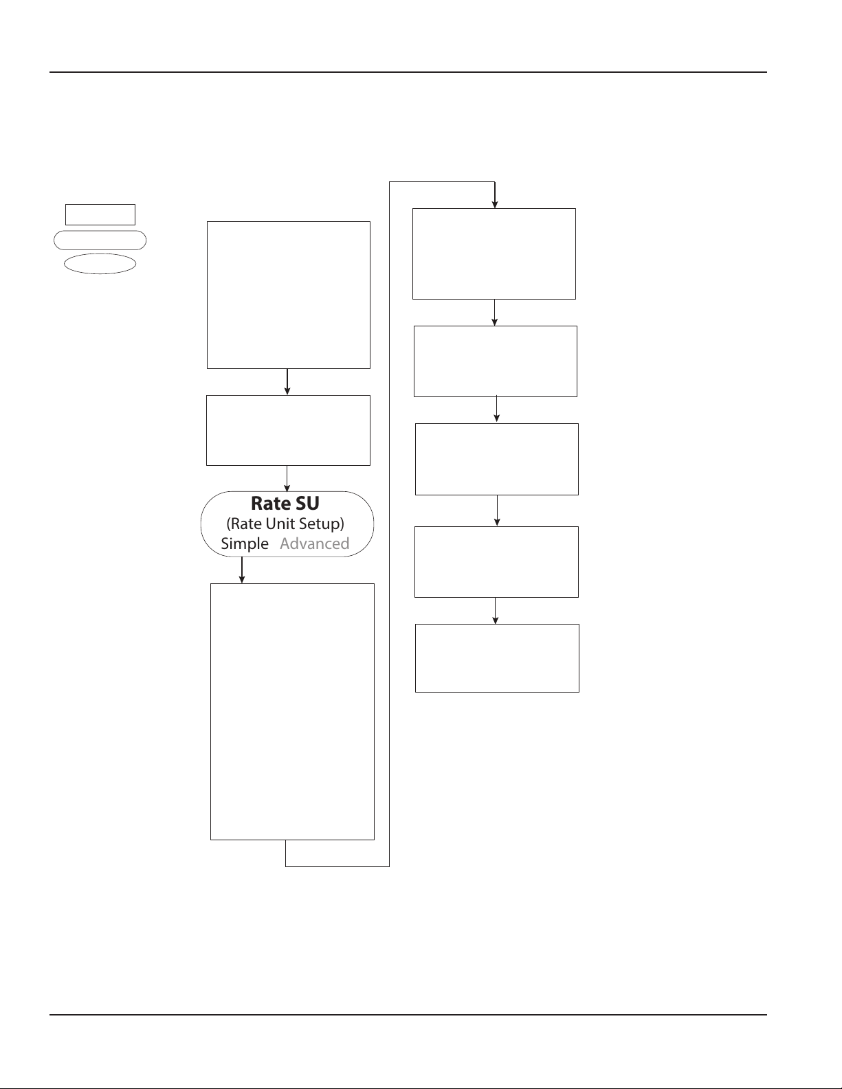
Standard ER-500, Rate SU is Set to Simple
Shape Key
Basic Menu
Extended Menu
Sub Menu
START
KFacUnt
(K-Factor Unit)
Pul/Gal
Pul/m³
Pul/Ltr
Pul/Ft³
=
Pulses/Gallon
=
Pulses/meter³
=
Pulses/Liter
=
Pulses/Ft³
KFactor
(K-Factor Value)
Numeric Entry
Flo Unt
(Rate/Total Units)
GPM
=
Gallons/Min
Gal
=
Gallons
OB/D
=
Oil Barrel/Day
BBL
=
Barrels
m³/D
=
Meters³/Day
m³
=
Meters³
m³/H
=
Meters³/Hour
m³
=
Meters³
LPM
=
Liters/Min
Ltr
=
Liters
PulsOut
(Pulse Output)
Disable
Enable
Fl=20mA
(Flow at 20 mA)
Numeric Entry
Clr G-T
(Clear Grand Total)
NO
YES
Passwd
(Password)
Numeric Entry
RstPswd
(Reset Password)
Numeric Entry
DSY-PM-00028-EN-02Page 10 February 2017
Page 11
Advanced ER-500, Basic Menu
Menu Structure
Shape Key
Basic Menu
Extended Menu
Sub Menu
START
KFacUnt
(K-Factor Unit)
Pul/Gal
Pul/m³
Pul/Ltr
Pul/Ft³
=
Pulses/Gallon
=
Pulses/meter³
=
Pulses/Liter
=
Pulses/Ft³
KFactor
(K-Factor Value)
Numeric Entry
RateInt
(Rate time interval)
=
Sec
Second
=
Min
Hour
Day
Minute
=
Hour
=
Day
RateUnt
(Unit/interval=T)
GPT
=
Gallons/T
LB/T
=
Liquor Barrel/T
OB/T
=
Oil Barrel/T
AF/T
=
Acre Feet/T
ML/T
=
Million Liters/T
LPT
=
Liters/T
m³/T
=
Meters³/T
Ft³/T
=
Feet³/T
MG/T
=
Million
Gallons/T
MASS
Kg/T
=
Kilograms/T
Lb/T
=
Pounds/T
TotalUnt
(Totalizer Unit)
Gal
=
Gallons
LBL
=
Liquor Barrel
OBL
=
Oil Barrel
AFt
=
Acre Feet
MLt
=
Million Liters
LPT
=
Liters
m³
=
Meters³
Ft³
=
Feet³
MGa
=
Million
Gallons
MASS
Kgs
=
Kilograms
Lbs
=
Pounds
TotlMult
(Totalizer Multiplier)
× 1000
×100
×10
0.1
0.01
1
=
× 100
=
× 10
=
× 1
=
× 0.1
=
× 0.01
=
×1000
Spec Gr
(Specic Gravity)
Numeric Entry
PulsOut
(Pulse Output)
Disable
Enable
Fl=20mA
(Flow at 20 mA)
Numeric Entry
Clr G-T
(Clear Grand Total)
NO
YES
Passwd
(Password)
Numeric Entry
Menu item appears
only when MASS
units are selected.
DSY-PM-00028-EN-02 Page 11 February 2017
RstPswd
(Reset Password)
Numeric Entry
Page 12

Rate SU
(Rate Unit Setup)
Simple Advanced
Menu Structure
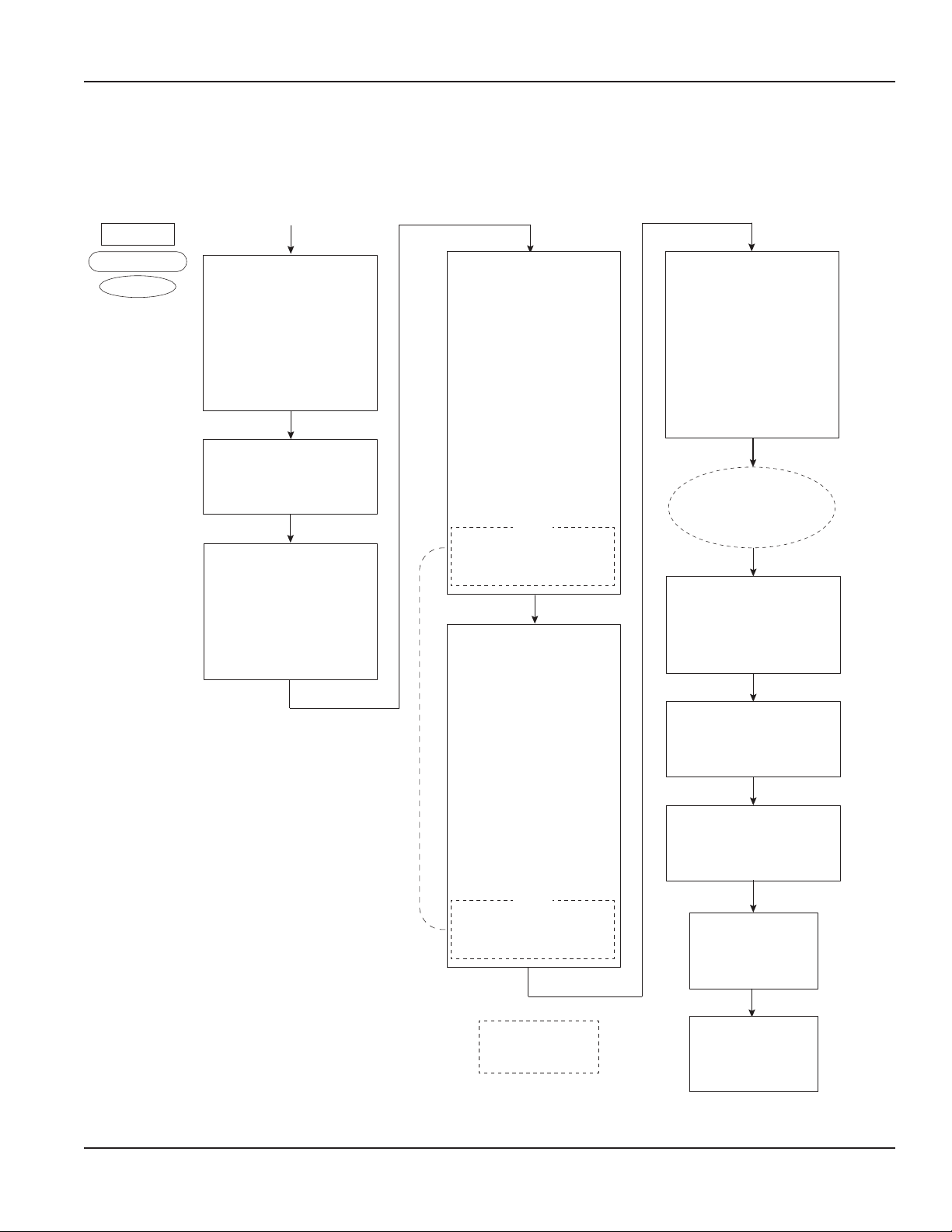
Standard ER-500, Rate SU is Set to Advanced
Shape Key
Basic Menu
Extended Menu
Sub Menu
START
Display (Options)
Flow
Flow GT = Grand Total
Test
KFacUnt
(K-Factor Unit)
Pul/Gal
Pul/m³
Pul/Ltr
Pul/Ft³
=
Pulses/Gallon
=
Pulses/meter³
=
Pulses/Liter
=
Pulses/Ft³
KFactor
(K-Factor Value)
Numeric Entry
RateInt
(Rate time interval)
=
Sec
Second
=
Min
Minute
=
Hour
Day
=
Hour
Day
RateUnt
(Unit/interval=T)
GPT
=
Gallons/T
LB/T
=
Liquor Barrel/T
OB/T
=
Oil Barrel/T
AF/T
=
Acre Feet/T
ML/T
=
Million Liters/T
LPT
=
Liters/T
m³/T
=
Meters³/T
Ft³/T
=
Feet³/T
MG/T
=
Million
Gallons/T
MASS
Kg/T
=
Kilograms/T
Lb/T
=
Pounds/T
TotalUnt
(Totalizer Unit)
Gal
=
Gallons
LBL
=
Liquor Barrel
OBL
=
Oil Barrel
AFt
=
Acre Feet
MLt
=
Million Liters
LPT
=
Liters
m³
=
Meters³
Ft³
=
Feet³
MGa
=
Million
Gallons
MASS
Kgs
=
Kilograms
Lbs
=
Pounds
TotlMult
(Totalizer Multiplier)
× 1000
×100
×10
0.1
0.01
1
=
× 100
=
× 10
=
× 1
=
× 0.1
=
× 0.01
=
×1000
Spec Gr
(Specic Gravity)
Numeric Entry
Scale F
(Scale Factor)
Numeric Entry
SetTotl
(Set Total Value)
Numeric Entry
Cuto
(Low Flow Cuto)
Numeric Entry
Damping
(Display Damping)
Numeric Entry
Continued on
next page.
Menu item appears
only when MASS
units are selected.
DSY-PM-00028-EN-02Page 12 February 2017
Page 13

Standard ER-500, Rate SU is Set to Advanced (continued)
Continued from
previous page.
Menu Structure
PulsOut
(Pulse Output)
Disable
Enable
Fl=20mA
(Flow at 20 mA)
Numeric Entry
4-20Cal
(Calibrate 4-20)
NO
YES
4mA Out
(4 mA Output)
Numeric Entry
20mA Out
(20 mA Output)
Numeric Entry
4-20Tst
(4-20 mA Output)
Numeric Entry
Linear
(Linearization)
Lin Pts = Linear Points (2 to10)
Numeric Entry
Clr G-T
(Clear Grand Total)
NO
YES
Passwd
(Password)
Numeric Entry
RstPswd
(Reset Password)
Numeric Entry
Freq#1
(Frequency 1)
Numeric Entry
Coef#1
(Coecient 1)
Numeric Entry
Freq#(x)
(Frequency 2-10)
Numeric Entry
Coef#(x)
(Coecent 2-10)
Numeric Entry
DSY-PM-00028-EN-02 Page 13 February 2017
Page 14

Menu Structure
Advanced ER-500, Advanced Menu
Shape Key
Basic Menu
Extended Menu
Sub Menu
START
Display (Options)
Flow
Flow GT = Grand Total
Test
KFacUnt
(K-Factor Unit)
Pul/Gal
Pul/m³
Pul/Ltr
Pul/Ft³
=
Pulses/Gallon
=
Pulses/meter³
=
Pulses/Liter
=
Pulses/Ft³
KFactor
(K-Factor Value)
Numeric Entry
RateInt
(Rate time interval)
=
Sec
Second
=
Min
Hour
Day
Minute
=
Hour
=
Day
RateUnt
(Unit/interval=T)
GPT
=
Gallons/T
LB/T
=
Liquor Barrel/T
OB/T
=
Oil Barrel/T
AF/T
=
Acre Feet/T
ML/T
=
Million Liters/T
LPT
=
Liters/T
m³/T
=
Meters³/T
Ft³/T
=
Feet³/T
MG/T
=
Million
Gallons/T
MASS
Kg/T
=
Kilograms/T
Lb/T
=
Pounds/T
TotalUnt
(Totalizer Unit)
Gal
=
Gallons
LBL
=
Liquor Barrel
OBL
=
Oil Barrel
AFt
=
Acre Feet
MLt
=
Million Liters
LPT
=
Liters
m³
=
Meters³
Ft³
=
Feet³
MGa
=
Million
Gallons
MASS
Kgs
=
Kilograms
Lbs
=
Pounds
TotlMult
(Totalizer Multiplier)
× 1000
×100
×10
0.1
0.01
1
=
× 100
=
× 10
=
× 1
=
× 0.1
=
× 0.01
=
×1000
Spec Gr
(Specic Gravity)
Numeric Entry
Scale F
(Scale Factor)
Numeric Entry
SetTotl
(Set Total Value)
Numeric Entry
Cuto
(Low Flow Cuto)
Numeric Entry
Damping
(Display Damping)
Numeric Entry
Continued on
next page.
Menu item appears
only when MASS
units are selected.
DSY-PM-00028-EN-02Page 14 February 2017
Page 15

Advanced ER-500, Advanced Menu (continued)
Continued from
previous page.
Menu Structure
PulsOut
(Pulse Output)
Disable
Enable
Fl=20mA
(Flow at 20 mA)
Numeric Entry
4-20Cal
(Calibrate 4-20)
NO
YES
4mA Out
(4 mA Output)
Numeric Entry
20mA Out
(20 mA Output)
Numeric Entry
4-20Tst
(4-20 mA Output)
Numeric Entry
Linear
(Linearization)
Lin Pts = Linear Points (2 to10)
Numeric Entry
Freq#1
(Frequency 1)
Numeric Entry
Coef#1
(Coecient 1)
Numeric Entry
Modbus
Disable
Enable
Modbus Address (1 to127)
SetPT1
(Setpoint 1)
Passwd
Numeric Entry
Password
HystSP1
(Hysteresis1)
Passwd
Numeric Entry
Password
TripSP1
(Trip On 1)
Passwd
High Low
Password
SetPT2
(Setpoint 2)
Passwd
Numeric Entry
Password
HystSP2
(Hysteresis2)
Passwd
Numeric Entry
Password
TripSP2
(Trip On 2)
Passwd
High Low
Password
BusAddr
Numeric Entry
Passwd
(Password)
Numeric Entry
RstPswd
(Reset Password)
Numeric Entry
Freq#(x)
(Frequency 2-10)
Numeric Entry
Coef#(x)
(Coecent 2-10)
Numeric Entry
DSY-PM-00028-EN-02 Page 15 February 2017
Clr G-T
(Clear Grand Total)
NO
YES
Page 16

Programming
PROGRAMMING
OTE:N All of the following parameters appear in Extended Programming mode. Parameters with an asterisk (*) appear in
Programming mode as well.
Parameters
Select Display Function
The ER-500 monitor has three display selections— Flow, Grand Total and Test.
Flow
Use the Flow setting for normal operation of the monitor. In this mode, the display shows both the instantaneous flow rate
and current total simultaneously, see Figure 6.
2
Instantaneous
Flow Rate
Current
Total
Figure 6: Instantaneous flow rate and current total
Flow Grand Total
The Flow-GT setting forces the meter to alternate between the instantaneous flow and the grand total with roll-over counts,
see Figure 7.
The grand total is the accumulation of all the fluid that has gone through the meter since the last time the grand total was
cleared. This totalizer is in addition to the current total totalizer on the display and is always enabled.
In addition, the grand total screen displays the number of times the grand total has reached its maximum count (9,999,999)
and rolled over to zero.
1
Flow Rate
Units
Totalizer
Multiplier
Current Total Units
2
1
Roll-Overs
Total
Totalizer
Mode
Figure 7: Grand total
Roll-over
Indicator
Test
The Test setting places the monitor into a special diagnostic mode that shows the current input frequency and the
accumulated input counts. Figure 8 shows the layout for test mode values. The diagnostic mode makes it possible for you to
see precisely the frequency input the monitor is seeing and is very useful in troubleshooting and electrical noise detection.
At the Display prompt, press ENTER to view the current display setting. If the current display setting is correct, press ENTER to
advance to the next parameter. To change the display setting, press UP or RIGHT to scroll through the display options. Press
ENTER to save and advance to the KFacUnit parameter.
2
Input
Frequency
Figure 8: Test mode screen
1
Totalizer
Counts
DSY-PM-00028-EN-02Page 16 February 2017
Page 17

Programming
Select Display's K-factor Unit*
At the KFacUnt prompt, press ENTER. The display shows the current K-factor unit. If the current selection is correct, press
ENTER to advance to the next parameter. To change the K-factor unit, press UP or RIGHT to scroll to the correct unit. The units
should match the units that the meter was calibrated in. Press ENTER to save and advance to the KFactor parameter.
Enter Flow Sensor's K-factor*
OTE:N The K-factor supplied with your meter or calculated from calibration data is needed to complete this step.
At the KFactor prompt, press ENTER. The most significant digit in the K-factor flashes. If the current K-factor is correct, press
ENTER to advance to the next parameter. To change the K-factor, press UP to increment the digit until it matches the meter’s
first K-factor digit. Press RIGHT to advance to the next digit. Repeat this process until all K-factor digits have been entered.
Press ENTER to save the K-factor and advance to the RateInt parameter.
OTE:N The number of digits available before and after the decimal point is determined by the bore size of the flow sensor
being used. The largest K-factors are associated with the smallest bore sizes. The maximum allowable K-factor is
99999.9. The minimum must be at least 1.000. If an out-of-range number is entered, the display flashes Limit and
refuses the entry.
Select Rate (Time) Interval*
At the RateInt prompt, press ENTER. The monitor flashes the current time interval. If the current selection is correct, press
ENTER to advance to the next parameter. To change to an alternate time interval, press UP or RIGHT to scroll to the correct
time interval. Press ENTER to save and advance to the RateUnt parameter.
Select Flow Rate Units*
At the RateUnt prompt, press ENTER. The monitor flashes the current rate unit. If the current selection is correct, press ENTER
to advance to the next parameter. To change to an alternate unit, press UP or RIGHT to scroll to the correct rate unit and press
ENTER to save and advance to the TotlUnt parameter.
Select Units of Measure for Total*
At the TotlUnt prompt, press ENTER. The monitor flashes the current total units. If the current selection is correct, press ENTER
to advance to the next parameter. To change to an alternate unit, press UP or RIGHT to scroll to the correct totalization unit.
Press ENTER to save and advance to the TotlMul parameter.
Select a Total Multiplier*
This parameter displays the accumulated flow total in multiples of 10. For example, if the optimum totalization unit is 1000
gallons, the unit total display increments by one digit for every 1000 gallons monitored. In Run mode, at 1000 gallons the total
monitor reads 1, at 3000 gallons, the total display reads 3. This feature eliminates having to look at a total, count the digits,
and mentally insert commas for each 1000 multiple.
At the TotlMul prompt, press ENTER . The monitor shows the current total multiplier. If the selection is correct, press ENTER to
advance to the next parameter. To change to an alternate multiplier, press UP or RIGHT to scroll to the correct multiplier unit
and press ENTER to and advance to the next parameter.
OTE:N If the RateUnt or TotlUnt parameter has been set to pounds or kilograms, the monitor advances to the Spec Gr
parameter. At any other setting, the monitor advances to Scale F. If pounds or kilograms have not been chosen, see
Enter a Scale Factor on page 18.
OTE:N If you are in Programming mode, the monitor advances to the PulsOut parameter.
See Totalizer Pulse Output* on page 19.
Enter a Specific Gravity Value*
Mass readings in the ER-500 monitor are not temperature or pressure compensated so it is best to enter the specific gravity
of the fluid as close to the system running temperature as possible. As liquids are essentially incompressible, pressure
compensation is not necessary for liquids.
At the Spec Gr prompt, press ENTER. The most significant digit of the current specific gravity flashes. If the current specific
gravity is correct, press ENTER to advance to the next parameter. To change to an alternate specific gravity, press UP to
increment the flashing digit until you reach the first digit of the new specific gravity. Press RIGHT to move to the next digit.
When all digits have been entered, press ENTER to save and advance to the Scale F parameter.
DSY-PM-00028-EN-02 Page 17 February 2017
Page 18

Programming
Enter a Scale Factor
The scale factor is used to force a global span change. For example, in Run mode the display is reading a consistent three
percent below the expected values at all flow rates. Rather than changing the K-factor and linearization parameters
individually, the scale factor can be set to 1.03 to correct the readings. The range of scale factors is from 0.10…5.00. The
default scale factor is 1.00.
At the Scale F prompt, press ENTER. The first digit of the existing scale factor flashes. If the current selection is correct, press
ENTER to advance to the next parameter. To change to an alternate scale factor, press UP to increment the display digit until
it matches the first digit of the new scale factor. Press RIGHT to advance to the next digit. Repeat for all digits. Press ENTER to
save and advance to the SetTotl parameter.
OTE:N If the number you enter is out of range, the display flashes Limit and refuses the entry.
Preset Total
The preset total parameter sets the totalizer to a predetermined amount. The preset can have seven digits up to 8,888,888.
At the SetTotl prompt, press ENTER. The monitor displays the current set total. If the set total is correct, press RIGHT to
advance to the next parameter. To change the set total, press ENTER again. The first digit of the current preset total flashes.
Press UP to increment the display digit until it matches the first digit of the correct preset. Press RIGHT to advance to the next
digit. Repeat for all digits. Press ENTER to save and advance to the Cutoff parameter.
OTE:N If the number you enter is out of range the display, flashes Limit and refuses the entry.
Low Flow Cutoff
The flow cutoff shows low flow rates (that can be present when pumps are off and valves are closed) as zero flow on the flow
monitor. A typical value would be about five percent of the flow sensor’s maximum flow.
Enter the low flow cutoff as an actual flow value. For example, if the maximum flow rate for the flow sensor was 100 gpm, set
the low flow cutoff value to 5.0.
At the Cutoff prompt, press ENTER. The first digit of the current low flow cutoff flashes. If the current selection is correct,
press ENTER to advance to the next parameter. To change the low flow cutoff, press UP to increment the display digit until it
matches the first digit of the new low flow cutoff value. Press RIGHT to advance to the next digit. Repeat for all digits. Press
ENTER to save and advance to the Damping parameter.
OTE:N If the number you enter is out of range the display, flashes Limit and refuses the entry.
Damping Factor
The damping factor is increased to enhance the stability of the flow readings. Damping values are decreased to allow the
monitor to react faster to changing values of flow. This parameter can be any value between 0…99%, with 0 being the default.
At the Damping prompt, press ENTER. The most significant digit of the current setting flashes. If the current selection is
correct, press ENTER to advance to the next parameter. To change the damping value, press UP to increment the display digit
until it matches the new damping value. Press RIGHT to advance to the next digit. Press ENTER to save and advance to the
PulsOut parameter.
DSY-PM-00028-EN-02Page 18 February 2017
Page 19

2.2
Internal
2.2
Programming
Totalizer Pulse Output*
The PulsOut parameter can be either enabled or disabled. When enabled, this output generates a fixed width 30 mS duration
pulse every time the least significant digit of the totalizer increments. The amplitude of the pulse is dependent on the voltage
level of the supply connected to the pulse output and is limited to a maximum 28V DC.
At the PulsOut prompt, press ENTER. The monitor displays the current setting. If the setting is correct, press ENTER to
advance to the next parameter. To change the parameter press UP or RIGHT to toggle between Disable and Enable. To save
your selection, press ENTER to advance to the Fl=20mA parameter.
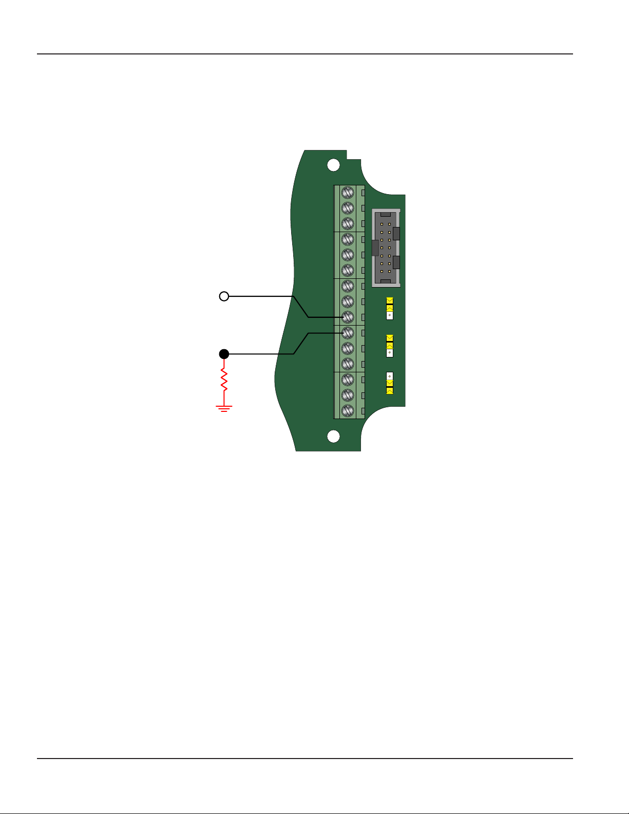
The ER-500 monitor provides two types of totalizer pulses. The basic open drain FET output provides a ground referenced
output pulse that swings between about 0.7V DC and VCC, see Figure 9 on page 19.
TR_B
P1
TR_A
RS485 Gnd
Setpoint 1
Setpoint 2
Gnd
+
Freq. In
…10K
Pull-up
Resistor
Open Drain FET
Total Pulse Output
V
CC
Maximum
100 mA
4-20mA
Iso Total Pluse
Total Reset
Total Pluse
Signal Gnd
JP1
–
+
–
JP2
+
–
JP3
TB1
Pulse
Mag
High
Low
Input Total Pulse Signal
OC
Iso
Figure 9: Open drain connections
The isolated pulse output (ISO), see Figure 10, is again an open collector output with the emitter of the transistor connected
to the negative output terminal and is not referenced to ground. This output is optically isolated from the input signal for
systems that require a totally isolated output pulse.
…10K
Pull-up
Resistor
Isolated Output
TR_B
TR_A
RS485 Gnd
Setpoint 1
Setpoint 2
Freq. In
4-20mA
Iso Total Pluse
Total Reset
OC Total Pluse
Signal Gnd
Gnd
+
–
+
–
+
–
Total Pulse
–V
V
CC
Maximum
100 mA
Figure 10: Opto-isolated open collector connections
P1
P1
JP1
JP1
Input Total Pulse Signal
Input Total Pulse Signal
Pulse
Mag
JP2
JP2
OC
Iso
JP3
JP3
High
Low
Internal
TB1
Both outputs have a maximum current capacity of 100 mA and require a pull-up resistor. The value of the pull-up resistor is
dependent on the supply voltage and the maximum current required by the load.
DSY-PM-00028-EN-02 Page 19 February 2017
Page 20

Programming
Flow 20 mA*
When the display is operated using loop power, the flow rate that corresponds to 20 mA must be set. This setting normally
represents the maximum rate of the flow sensor connected to the display but other entries are possible.
At the Fl=20mA prompt, press ENTER. The first digit of the current setting flashes. If the current setting is correct, press ENTER
to advance to the next parameter. If the current setting requires a change, press UP to increment the display digit until it
matches the first digit of the required maximum flow value. Press RIGHT to advance to the next digit. Repeat for all of the
maximum flow at 20 mA digits. Press ENTER to save and advance to the 4-20Cal parameter.
OTE:N In Programming mode, the monitor advances to the Clr G-T parameter. See Clear Grand Total* on page 24.
4-20 mA Calibration
This setting allows the fine adjustment of the Digital to Analog Converter (DAC) that controls 4…20 mA output. The
4…20 mA output is calibrated at the factory and under most circumstances does not need to be adjusted. If the output needs
to be adjusted for any reason the 4…20 mA calibration procedure is used.
At the 4-20Cal prompt, press ENTER. The monitor displays No. If you do not need to complete the 4…20 mA calibration, press
ENTER to advance to the Linear parameter. See Linearization on page 21. To complete the 4…20 mA calibration, press UP or
RIGHT to change the display to Yes . Press ENTER to advance to the 4mA Out parameter.
4 mA Adjustment
To set the 4mA Out value, connect an ammeter in series with the loop power supply as shown in Figure 11. The 4 mA DAC
setting is typically 35…50. At the 4mA Out prompt, press UP to increase or RIGHT to decrease the current output while
monitoring the ammeter. When a steady 4 mA reading is established on the ammeter, press ENTER on the monitor to save
the output and advance to the 20mAOut parameter.
LOG
HOLD
FAST MAX MIN AVG
51000
0 0
MEM
AUTO
HM
HOLD MIN MAX REL
CANCEL SAVE NO
Hz % ms RANGE
nS
W
mV
ac+dc
V
ac+dc
mV
dB
V
dB
OFF
mA
A
µA
10A MAX
400mA
FUSED
FUSED
COM
VIEW MEM
CLEAR MEM
MS
°F
°C
CAT III
1000V
AutoHOLD FAST MIN MX LOGGING YES
SETUP
MANUAL
ac+dc
TEMPERATURE
TR_B
TR_A
RS485 Gnd
%
A
mA
µA
A
mA
ac+dc
µA
W
V
4-20 mA
Current Loop
(10…28V DC)
POWER
Setpoint 1
Setpoint 2
Freq. In
4-20mA
Iso Total Pluse
Total Reset
OC Total Pluse
Signal Gnd
Gnd
+
–
+
–
+
–
SUPPLY
P1
JP1
Input Total Pulse Signal
Pulse
Mag
JP2
OC
Iso
JP3
High
Low
TB1
Figure 11: 4-20 mA calibration setup
20 mA Adjustment
The 20 mA adjustment is performed using the same procedure as the 4 mA adjustment.
4-20 mA Test
The ER-500 monitor contains a diagnostic routine that allows the simulation of mA output values between 4 …20 to check
output tracking. At the 4-20Tst prompt, the current flashes. Press UP to increase the simulated mA output in increments of
1 mA. Press RIGHT to decrease the mA output. The ammeter should track the simulated mA output. If a 4…20 mA test is not
necessary, press ENTER to advance to the Linear parameter.
OTE:N Press ENTER when the monitor is in test mode to exit the test mode and move on to the next
programming parameter.
DSY-PM-00028-EN-02Page 20 February 2017
Page 21

Programming
Linearization
To increase accuracy, linearize the monitor. The linearization function accepts a maximum of ten points and requires
additional calibration data from the meter being used with the monitor. Typically, calibration information can be obtained
in three, five and ten points from the flow meter’s manufacturer. If linearization is not needed, press RIGHT to advance to
the Modbus parameter. See Modbus on page 22. To complete linearization, press ENTER at the Linear prompt. The monitor
advances to the Lin Pts parameter.
Number of Points
The Lin Pts value displays. If the number of points is set to 0, linearization is disabled. Press ENTER. The most significant digit
of the number of points entry begins to flash. The first number can be a 1 or a 0 only. Press UP to change the first digit. Press
RIGHT to move to the least significant digit.
OTE:N If the number you enter is out of range the, display flashes Limit and refuses the entry.
Press ENTER to advance to the Freq#1 prompt.
OTE:N If the number of linear points is set to 1, the ER-500 monitor assumes that you are entering the maximum frequency
and coefficient. Further, the meter assumes that the implied first point is at a frequency of 0 Hz and a coefficient of 0.
Frequency
At the Freq#1 prompt, press ENTER. The first digit of the first linear point’s frequency input flashes. Press UP to increment
the numerical values and RIGHT to change the position of the number being entered. When the frequency value input is
complete, press ENTER to save and advance to the Coef#1 parameter.
Coefficient
The coefficient is the value applied to the nominal K-factor to correct it to the exact K-factor for that point. The coefficient is
calculated by dividing the average (nominal) K-factor for that point by the actual K-factor for the flow meter.
Linear Coecient =
Nominal K-Factor
Actual K-Factor
At the Coef#1 prompt, press ENTER. The first digit of the coefficient flashes. Press UP to increment the digit, and RIGHT to
move to the next digit. When all digits have been entered, press ENTER to save and advance to the next frequency input.
Continue entering pairs of frequency and coefficient points until all data has been entered. Press ENTER to save and advance
to the Modbus parameter.
OTE:N The frequency values must be entered in ascending order. If a lower frequency value is entered after a higher value
the ER-500 monitor flashes Limit followed by the minimum frequency value acceptable to the display.
Example:
The following is actual data taken from a one inch turbine flow sensor calibrated with water.
Unit Under Test (UUT) Calibration In GPM
Actual
GPM
UUT
Frequency
Hz Counts/Gallon GPM % Rate
UUT Actual
K-factor
(Hz x 60)
Nominal K
Linear
Coefficient
Raw Error
50.02 755.900 906.72 49.72 1.0060 0.59
28.12 426.000 908.96 28.02 1.0035 0.35
15.80 240.500 913.29 15.82 0.9987 -0.13
8.88 135.800 917.57 8.93 0.9941 -0.59
4.95 75.100 910.30 4.94 1.0020 0.20
Nominal K (NK) 912.144 — —
In this example the linear coefficient has already been calculated by the calibration program so all that is required is to enter
five into the Lin Pts parameter and then enter, in order, the five frequency and linear coefficient data pairs.
DSY-PM-00028-EN-02 Page 21 February 2017
Page 22

Programming
Modbus
The Modbus output parameter can be either enabled or disabled. When enabled, this output allows communications with the
ER-500 monitor using the Modbus RTU protocol. For additional information see Modbus Interface on page 27.
At the Modbus prompt, press ENTER. The current state of the Modbus output is shown. If the current state is correct, press
ENTER to advance to the next parameter. To change the modbus setting, press UP or RIGHT to toggle between states. When
the proper state displays, press ENTER to save and advance to the BusAddr parameter.
Bus Address
If the Modbus output is enabled, you must choose a valid Modbus address. Every device communicating over the RS485
communications bus using the Modbus protocol must have a unique bus address. Address values range from 0…127 with 0
being the default.
At the BusAddr prompt, press ENTER. The first digit of the address flashes. If the current setting is correct, press ENTER to
advance to the next parameter. To change the address, press UP to increment the display digit until it matches the first digit
of the new bus address. Press RIGHT to advance to the next digit. Repeat for all digits of the address. Press ENTER to save the
new address and advance to the SetPt 1 parameter.
Setpoints
Setpoints allow the meter to signal when a specific flow condition has been achieved. They are commonly used to indicate
high or low flow conditions that need attention. The ER-500 monitor has two open collector outputs controlled by the
setpoint function.
The setpoint transistors have the same current limitations and setup requirements as the totalizing pulse output transistors
described previously. See Figure 12 on page 23 for control output transistor connections.
Both setpoint 1 and setpoint 2 are configured using the same procedures, but the hysteresis and tripping conditions can be
different for each setpoint output.
OTE:N In most instances, the current capacity of an open collector transistor is not sufficient to operate old style counters
that relied on relay contact closures. When used with basic counting circuits, a solid-state relay is needed. See Figure
13 on page 23 for a connection example.
DSY-PM-00028-EN-02Page 22 February 2017
Page 23

2.2
V
Minimum
Maximum
Hysteresis
Programming
Setpoint 1
The setpoint is the flow value at which the output transistor changes state. It is set using the same units as the rate units.
…10k
CC
Pull-up
Resistor
Open Collector
Control Output
1 and 2
100 mA
Maximum
RS485 Gnd
Setpoint 1
Setpoint 2
Freq. In
4-20mA
Iso Total Pluse
Total Reset
OC Total Pluse
Signal Gnd
TR_B
TR_A
Gnd
+
–
+
–
+
–
P1
OUTPUT
1 2
Solid State
Relay
4 3
JP1
Input Total Pulse Signal
Pulse
Mag
High
Low
TB1
Internal
JP2
OC
Iso
JP3
INPUT
2.2 to 10k
Pull-up
Resistor
V
CC
100 mA
Maximum
Open Collector
Control Output
1 or 2
RS485 Gnd
Setpoint 1
Setpoint 2
Freq. In
4-20mA
Iso Total Pluse
Total Reset
OC Total Pluse
Signal Gnd
TR_B
P1
TR_A
Gnd
+
JP1
Input Total Pulse Signal
–
Pulse
+
–
JP2
+
–
JP3
TB1
Mag
High
Low
Internal
OC
Iso
Figure 12: Setpoint output Figure 13: Typical solid state relay connections
At the SetPt 1 prompt, press ENTER. The most significant digit of the current setting flashes. If the current setting is correct,
press ENTER to advance to the next parameter. To change the current setting, press RIGHT to advance to the first digit of the
required set point value. Press UP to increment the digit until it matches the first number of the required set point. Repeat for
all the digits the set point. Press ENTER to save the new set point and advance to the HystSP1 parameter.
Hysteresis 1
Hysteresis is used to modify how the output transistor reacts around a setpoint by taking recent history into account.
Hysteresis prevents an output from turning on and off rapidly when the programmed flow rate is at or very near the setpoint.
For example, a low flow alarm is set to activate when the flow falls below a pre-programmed point. When the flow is reduced
to the setpoint, even minute changes of flow above the setpoint turns the output off, disabling the alarm. Without hysteresis,
if the flow rate fluctuates slightly above and below the setpoint, the output rapidly cycles between on and off states. See
Figure 14. The hysteresis value is set using the same units as the rate units.
At the HystSP1 prompt, press ENTER. The most significant digit of the current setting flashes. If the current setting is correct,
press ENTER to advance to the next parameter. To change the current setting, press RIGHT to advance to the first digit of the
required hysteresis value. When the correct place is reached, press UP to increment the digit until it matches the first number
of the required hysteresis. Press RIGHT to advance to the next digit of the required hysteresis value and press UP to increment
the display digit until it matches the next digit of the required hysteresis. Repeat this step for the all the digits of the hysteresis
and then press ENTER to save the new hysteresis and advance to the next parameter.
Flow
Output OFF
OFF Setpoint
ON Setpoint
Figure 14: Setpoint actions
Flow
Output ON
DSY-PM-00028-EN-02 Page 23 February 2017
Page 24

Minimum
Maximum
(2 gpm)
Normally Open
Programming
Trip SP 1
The trip parameter can be set for either High or Lo. When set to high, the open collector transistor stops conducting and sends
the output high when the setpoint is reached. The output will not go low again until the flow rate falls below the setpoint
minus the hysteresis value. When set to low, the open collector transistor starts conducting and sends the output low when
the setpoint is reached. The output will not go high again until the flow rate exceeds the setpoint plus the hysteresis value.
For example, if the set point is 10 gpm, the hysteresis is set to 2 gpm and the trip setpoint is set to High (see Figure 15). When
the flow goes above 10 gpm the OC transistor stops conducting and the output goes high. The output stays high until the
flow rate drops below 8 gpm which is the setpoint (10 gpm) minus the hysteresis (2 gpm).
Flow
OFF (8 gpm)
Setpoint (10 gpm)
Output ON
Flow
Output OFF
Hysteresis
Figure 15: Setpoint example
At the TripSP1 prompt, press ENTER. The tripping condition setting is displayed. If the current setting is correct, press ENTER
to advance to the next parameter.
If the current setting requires a change, press RIGHT to advance to the alternate choice. Once the correct choice is displayed,
press ENTER to save the new trip condition and advance to the next parameter.
Clear Grand Total*
At the Clr G-T prompt, press ENTER. The flow monitor displays No. To clear the grand total press, UP or RIGHT to change from
No to Yes. Press ENTER to select Ye s and advance to the next parameter. The totalizer can also be reset using a hardware reset
as shown in Figure 16.
TR_B
P1
TR_A
RS485 Gnd
Setpoint 1
Setpoint 2
Gnd
+
Freq. In
JP1
Input Total Pulse Signal
–
Pulse
Mag
OC
Iso
High
Low
TB1
Pushbutton
Switch
4-20mA
Iso Total Pluse
Total Reset
OC Total Pluse
Signal Gnd
+
–
JP2
+
–
JP3
Figure 16: Hardware reset
DSY-PM-00028-EN-02Page 24 February 2017
Page 25

K-factors Explained
Password*
The password setting restricts access to the Programming and Extended Programming modes. Initially, the password is set to all
zeros and any user can modify the parameter settings. To change the password, press ENTER at the Passwd prompt. The first
digit flashes. Press UP to increment the digit and RIGHT to advance to the next digit. After entering all digits, press ENTER to
store the password and advance to RstPswd. The new password is now required to enter either programming mode. With this
password set, any user is able to reset the stored totals on the monitor.
Reset Password*
The reset password parameter restricts resetting the totals on the monitor. The Passwd must also be set to restrict the total
reset. Initially, the password is set to all zeros and any user can reset the stored totals on the monitor. To change the password,
press ENTER at the RstPswd prompt. The first digit flashes. Press UP to increment the digit and RIGHT to advance to the next
digit. After entering all digits, press ENTER to store the password and return to the Fluid parameter. The reset password is now
required to reset the totals on the monitor.
OTE:N Entering a password in the Passwd screen and leaving the password blank in the RstPswd screen allows for total resets
(not requiring a password), but restricts programming modification.
KFACTORS EXPLAINED
The K-factor (with regards to flow) is the number of pulses that must be accumulated to equal a particular volume of fluid. You
can think of each pulse as representing a small fraction of the totalizing unit.
An example might be a K-factor of 1000 (pulses per gallon). This means that if you were counting pulses, when the count total
reached 1000, you would have accumulated 1 gallon of liquid. Using the same reasoning, each individual pulse represents an
accumulation of 1/1000 of a gallon. This relationship is independent of the time it takes to accumulate the counts.
The frequency aspect of K-factors is a little more confusing because it also involves the flow rate. The same K-factor number,
with a time frame added, can be converted into a flow rate. If you accumulated 1000 counts (one gallon) in one minute, then
your flow rate would be 1 gpm. The output frequency, in Hz, is found simply by dividing the number of counts (1000) by the
number of seconds (60) to get the output frequency.
1000 ÷ 60 = 16.6666 Hz. If you were looking at the pulse output on a frequency counter, an output frequency of 16.666 Hz
would be equal to 1 gpm. If the frequency counter registered 33.333 Hz (2 × 16.666 Hz), then the flow rate would be 2 gpm.
Finally, if the flow rate is 2 gpm, then the accumulation of 1000 counts would take place in 30 seconds because the flow rate,
and hence the speed that the 1000 counts is accumulated, is twice as great.
Calculating K-factors
Many styles of flow meters are capable of measuring flow in a wide range of pipe sizes. Because the pipe size and volumetric
units the meter will be used on vary, it may not possible to provide a discrete K-factor. In the event that a discrete K-factor is
not supplied then the velocity range of the meter is usually provided along with a maximum frequency output.
The most basic K-factor calculation requires that an accurate flow rate and the output frequency associated with that flow
rate be known.
Example 1:
Known values are:
Frequency = 700 Hz
Flow Rate = 48 GPM
700 Hz × 60 sec = 42,000 pulses per min
42,000 pulses per min
K-factor
= =
48 gpm
875 pulses per gallon
DSY-PM-00028-EN-02 Page 25 February 2017
Page 26

A
A
2
7
ft
= 0.384 gallons
231 in
K-
42,000 pulses per min
99.1 gpm
n
Modbus Interface
Example 2:
Known values are:
Full Scale Flow Rate = 85 gpm
Full Scale Output Frequency = 650 Hz
650 Hz × 60 sec = 39,000 pulses per min
K-factor 458.82 pulses per gallon= =
39,000 pulses per min
85 gpm
The calculation is a little more complex if velocity is used because you first must convert the velocity into a volumetric flow
rate to be able to compute a K-factor.
To convert a velocity into a volumetric flow, the velocity measurement and an accurate measurement of the inside diameter
of the pipe must be known. Also needed is the fact that 1 US gallon of liquid is equal to 231 cubic inches.
Example 3:
Known values are:
Velocity = 4.3 ft/sec
Inside Diameter of Pipe = 3.068 in.
Find the area of the pipe cross section.
2
πr
rea =
3.068
rea
= π = π x
2
2.35 = 7.39 in
2
Find the volume in 1 ft of travel.
2
.3 in2 x 12 in (1 ft) =
88.71in
What portion of a gallon does 1 ft of travel represent?
3
88.71 in
3
So for every foot of fluid travel 0.384 gallons will pass.
What is the flow rate in gpm at 4.3 ft/sec?
0.384 gallons × 4.3 FPS × 60 sec (1 min) = 99.1 gpm
Now that the volumetric flow rate is known, all that is needed is an output frequency to determine the K-factor.
Known values are:
Frequency = 700 Hz (By measurement)
Flow Rate = 99.1 gpm (By calculation)
700 Hz × 60 sec = 42,000 pulses per gallon
factor
==
423.9 pulses per gallo
DSY-PM-00028-EN-02Page 26 February 2017
Page 27

Modbus Interface
MODBUS INTERFACE
A subset of the standard Modbus commands is implemented to provide access into the data and status of the ER-500
monitor. The following Modbus commands are implemented:
Command Description
01 Read Coils
03 Read Holding Registers
05 Force Single Coil
Type Bits Bytes Modbus Registers
Long Integer
Single Precision IEEE754
Modbus Register / Word Ordering
Each Modbus holding register represents a 16-bit integer value (2 bytes). The official Modbus standard defines Modbus as a
‘big-endian’ protocol where the most significant byte of a 16-bit value is sent before the least significant byte. For example,
the 16-bit hex value of ‘1234’ is transferred as ‘12’ ‘34’.
Beyond 16-bit values, the protocol itself does not specify how 32-bit (or larger) numbers that span over multiple registers
should be handled. It is very common to transfer 32-bit values as pairs of two consecutive 16-bit registers in little-endian word
order. For example, the 32-bit hex value of ‘12345678’ is transferred as ‘56’ ‘78’ ‘12’ ‘34’. Notice the Register Bytes are still sent in
big-endian order per the Modbus protocol, but the Registers are sent in little-endian order.
Other manufacturers store and transfer the Modbus Registers in big-endian word order. For example, the 32-bit hex value
of ‘12345678’ is transferred as ‘12’ ‘34’ ‘56’ ‘78’. It does not matter which order the words are sent, as long as the receiving
device knows which way to expect it. Since word order is a common problem between devices, many Modbus master
devices have a configuration setting for interpreting data (over multiple registers) as ‘little-endian’ or ‘big-endian’ word order.
This is also referred to as swapped or word swapped values and allows the master device to work with slave devices from
different manufacturers.
If the endianness is not a configurable option within the Modbus master device, it’s important to make sure it matches
the slave endianess for proper data interpretation. The ER-500 monitor actually provides two Modbus register maps to
accommodate both formats. This is useful in applications where the Modbus master cannot be configured for endianness.
32 4 2
32 4 2
Register Mappings
Data Component
Name
Spare 40100…40101 40200…40201 —
Flow Rate 40102…40103 40202…40203
Spare 40104…40105 40204…40205
Positive Totalizer 40106…40107 40206…40207
Grand Total Totalizer 40108…40109 40208…40209
Battery Voltage 40110…40111 40210…40211 x.xx
Spare 40112…40113 40212…40213 —
Long Integer
Format
For reference: If the ER-500 totalizer = 12345678 hex
Register 40106 would contain 5678 hex (Word Low)
Register 40107 would contain 1234 hex (Word High)
MODBUS Registers
Single Precision
Floating Point Format
DSY-PM-00028-EN-02 Page 27 February 2017
Available Units
Gallons, Liters, MGallons, Cubic Feet, Cubic Meters, Acre
Feet, Oil Barrel, Liquid Barrel, Feet, Meters, Lb, Kg, BTU,
MBTU, MMBTU, TON
Second, Minute, Hour, Day
Per
Page 28

Modbus Interface
Data Component
Name
Spare 40600…40601 40700…40701 –
Flow Rate 40602…40603 40702…40703
Spare 40604…40605 40704…40705
Positive Totalizer 40606…40607 40706…40707
Grand Total Totalizer 40608…40609 40708…40709
Battery Voltage 40610…40611 40710…40711 x.xx
Spare 40612…40613 40712…40713
Long Integer
MODBUS Registers
Format
Single Precision
Floating Point Format
Available Units
Gallons, Liters, MGallons, Cubic Feet, Cubic Meters, Acre
Feet, Oil Barrel, Liquid Barrel, Feet, Meters, Lb, Kg, BTU,
MBTU, MMBTU, TON
Second, Minute, Hour, Day
For reference: If the ER-500 totalizer = 12345678 hex
Register 40606 would contain 1234 hex (Word High)
Register 40607 would contain 5678 hex (Word Low)
Modbus Coil Description Modbus Coil Notes
Reset Running Totalizer 1
Reset Grand Totalizer 2
—
Alarm Setpoint 1 9 0 = Setpoint OFF, 1 = Setpoint ON
Alarm Setpoint 2 10 0 = Setpoint OFF, 1 = Setpoint ON
—
3…8 Spares
11…16 Spares
Forcing this coil ON will reset the running totalizer. After reset, the coil
automatically returns to the OFF state.
Forcing this coil ON will reset both the running totalizer and the grand totalizer.
After reset, the coil automatically returns to the OFF state.
Opcode 01 - Read Coil Status
This opcode returns the state of the alarm coils. The following Coils are defined:
Per
Coil # Description
9 Alarm Setpoint 1
10 Alarm Setpoint 2
11 and up Spare
Command: <addr><01><00><08><00><02><crc-16>
Reply: <addr><01><01><0x><crc-16>
Opcode 03 - Read Holding Registers
This opcode returns the input holding registers, such as flow rate or totalizer.
OTE:N Each value must be requested individually. Return of a block of registers is not implemented at this time.
Example requesting flow rate in floating point format.
Command: <addr><03><00><C9><00><02><crc-16>
Reply: <addr><03><02><data><data><crc-16>
Opcode 05 - Force Single Coil
This opcode sets the state of a single coil (digital output). The following Coil Registers are defined:
Coil # Description
1 Reset Totalizer
2 Grand Totals
3 and up Spares
The transition of coil from 0 to 1 will initiate function. This bit is auto reset to 0, so there is no need to set it to 0 after a totalizer
reset command.
Command: <addr><05><00><00><FF><00><crc-16>
Reply: <addr><05><00><00><FF><00><crc-16>
DSY-PM-00028-EN-02Page 28 February 2017
Page 29

Battery Replacement
BATTERY REPLACEMENT
Battery powered monitors use a single 3.6V DC D size, lithium battery. When replacement is necessary, use a clean fresh
battery to ensure continued trouble-free operation.
Replacement Batteries
Manufacturer Part Number
Badger Meter B300028
Xeno S11-0205-10-03
Tadiran TL-5930/F
2. Unscrew the four captive screws on the front panel to gain access to the battery (see Figure 17).
J1
KB/Display
TR_B
P1
TR_A
RS485 Gnd
2
1
Setpoint 1
Setpoint 2
Gnd
Unscrew
Captive Screws
+ –
+
Freq. In
JP1
Input Total Pulse Signal
–
Pulse
Mag
+
4-20mA
–
JP2
OC
+
Iso
Iso Total Pluse
–
JP3
High
Total Reset
P2
OC Total Pluse
Low
Signal Gnd
TB1
Figure 17: Opening the
3. Press the tab on the battery connector to release it from the circuit board (see Figure 18).
Press
Battery
REPLACE BATTER WITH
XEON S11-0205-10-03
OR TADIRAN TL-5930/F ONLY
P2
+ –
J1
KB/Display
WARNING- To reduce the risk of ignition
of a ammable atmosphere, batteries
must only be changed in an area known
to be nonammable.
RS485 Gnd
4-20 mA
ISO Total Pulse
Total Reset
OC Total Pulse
Signal Gnd
TR-A
TR-B
RS485 Gnd
Setpoint 1
Setpoint 1
Setpoint 2
Setpoint 2
Gnd
Freq. In
Freq. In
4-20mA
Iso Total Pluse
Total Reset
OC Total Pluse
Signal Gnd
Release
Tab
TR_B
P1
TR_A
Gnd
+
+
JP1
Input Total Pulse Signal
–
Pulse
-
Mag
+
+
–
JP2
-
OC
+
+
Iso
–
-
JP3
High
Low
TB1
Connector
Connector
Figure 18: Battery connection release.
4. Remove the old battery and replace it with new one.
5. Re-fasten the front panel screws.
Slide
Away
DSY-PM-00028-EN-02 Page 29 February 2017
Page 30

COM
Specications
SPECIFICATIONS
Simultaneously shows Rate and Total
5 x 7 Dot matrix LCD, STN fluid
LCD
Annunciators
Power
Inputs
Outputs
Safety
Certifications
Entity Parameters
EMC 2004/108/EC
Accuracy 0.05%
Response Time 1…100 seconds response to a step change input, user adjustable
Environmental
Limits
Materials Polycarbonate, stainless steel, polyurethane, thermoplastic elastomer, acrylic
Enclosure Ratings NEMA 4X/IP 66
6 Digit rate, 0.5 inch (12.7 mm) numeric
7 Digit total, 0.5 inch (12.7 mm) numeric
Engineering unit labels 0.34 inch (8.6 mm)
Alarm 1(1), Alarm 2 (2), Battery Level ( ), RS485 Communications (
Battery 3.6V DC lithium “D Cell” gives up to 6 years of service life
4…20 mA, two wire, 25 mA limit, reverse polarity protected, 7 V DC loop loss
Loop
Auto switching between internal battery and external loop power; includes isolation between
loop power and other I/O
Frequency Range 1…3500 Hz
Frequency Accuracy ±0.1%
Magnetic Pickup
Over Voltage Protection 28V DC
Trigger Sensitivity
30 mVp-p (High) or 60 mVp-p (Low) - (selected by circuit board
jumper)
Amplified Pulse Direct connection to amplified signal (pre-amp output from sensor)
Analog 4…20 mA 4…20 mA, two-wire current loop 25 mA current limit
One pulse for each Least Significant Digit (LSD) increment of the totalizer
Totalizing Pulse
Pulse Type
(selected by circuit board
jumper)
Maximum Voltage 28V DC
Opto-isolated (Iso) open collector transistor
Non-isolated open drain FET
Maximum Current Capacity 100 mA
Maximum Output
Frequency
16 Hz
Pulse Width 30 mS fixed
Open collector transistor Adjustable flow rate with programmable
dead band and phase.
Status Alarms
(Advanced Only)
Type
Maximum Voltage 28V DC
Maximum Current 100 mA
Pull-Up Resistor: External required (2.2 K ohm minimum, 10 K ohm maximum)
Modbus
(Advanced Only)
Data Configuration
and Protection
Modbus RTU over RS485, 127 addressable units / 2-wire network, 9600 baud, long integer and
single precision IEEE754 formats; retrieve: flow rate, job totalizer, grand totalizer, alarm status and
battery level; write: reset job totalizer, reset grand totalizer
Two 4-digit user selectable passwords; level one password enables Job Total reset only, level
two password enables all configuration and totalizer reset functions (Not Applicable on solar
powered units)
Class I Division 1, Groups C, D; Class II, Division 1 Groups E, F, G; Class III for US and Canada. Complies with UL 913 and
CSA C22.2 No. 157-92
4…20mA Loop V
Pulse Output V
Reset Input V
RS485 V
= 28V DC I
max
= 28V DC I
max
= 5V DC I
max
= 10V DC I
max
= 26 mA Ci = 0.5 F Li = 0 mH
max
= 100 mA Ci = 0 F Li = 0 mH
max
= 5 mA Ci = 0 F Li = 0 mH
max
= 60 mA Ci = 0 F Li = 0 mH
max
Sensor Input Voc = 2.5 V Isc = 1.8 mA C = 1.5 F La = 1.65 H
–22…158° F (–30…70° C); 0…90% humidity, non-condensing;
)
DSY-PM-00028-EN-02Page 30 February 2017
Page 31

MODEL NUMBERS
DIMENSIONS
Model Numbers
ER-500
A = Advanced
S = Standard
P2
+ –
A B C
5.0 in. (127.0 mm) 4.5 in. (114.3 mm) 2.6 in. (66.0 mm)
TROUBLESHOOTING GUIDE
Trouble Remedy
B
KB/Display
C
J1
TR_B
P1
TR_A
RS485 Gnd
2
1
2
1
Setpoint 1
Setpoint 2
Gnd
+
Freq. In
JP1
Input Total Pulse Signal
–
Pulse
Mag
Iso Total Pluse
OC Total Pluse
Total Reset
Signal Gnd
+
4-20mA
–
JP2
OC
+
Iso
–
JP3
High
Low
TB1
A
Battery Check battery voltage. Should be 3.6 V DC. If the input is 3.4V DC or lower, replace the battery.
No LCD
Display
Loop
power
No Rate or Total
Displayed
Flow Rate Display
Interprets Reading
Constantly
Flow Rate Indication
Erratic
Check 4…20 mA input. Voltage must be within the minimum and maximum supply voltage and
capable of supplying enough current to run the display. The input voltage is checked “across” or
in parallel with the 4…20 mA terminals and current is checked with the ammeter in series with
the 4…20 mA output.
Check connection from meter's transmitter to display input terminals.
Check turbine meter rotor for debris. Rotor should spin freely.
Check programming of flow monitor.
This is usually an indication of external noise. Keep all AC wires separate from DC wires.
Check for large motors close to the meter pickup.
Check for radio antenna in close proximity.
This usually indicates a weak signal. Replace pickup and/or check all connections.
Check for correct factor.
Check that the ILR transmitters meter size selection switch is set to the correct size.
DSY-PM-00028-EN-02 Page 31 February 2017
Page 32

NOTES ON CABLE ENTRY
NOTES ON CONTROL EQUIPMENT
WITH RESPECT TO EARTH.
1. CONTROL EQUIPMENT MUST NOT USE OR GENERATE MORE THAN 250 V,
1. ALL CABLE ENTRIES INTO THE ENCLOSURE MUST BE BROUGHT
THROUGH SUITABLY SIZED UL & CSA CERTIFIED LIQUID TIGHT
STRAIGHT THRU FITTINGS
NOTES ON FLOW SENSOR
1. INTERCONNECTING CABLE CAPACITANCE AND INDUCTANCE, PLUS THE
CAPACITANCE AND INDUCTANCE OF THE MAGNETIC PICKUP, MUST BE LESS
THAN OR EQUAL TO THE CAPACITANCE(Ca) AND THE INDUCTANCE(La) "TURBINE
INPUT" ENTITY PARAMETERS MARKED ON THE B3000 MONITOR AND TABLE 2.
Control Drawing
CONTROL DRAWING
V Max
I Max
Ci
Li
4-20mA Loop
28 Vdc
26mA
0.5µF
0.0mH
Pulse Output
28 Vdc
100mA
0.0µF
0.0mH
Reset Input RS485
5 Vdc
10 Vdc
5mA
60mA
0.0µF
0.0µF
0.0mH
0.0mH
Turbine Input
Voc = 3.5V
Isc = 3.6mA
Ca = 15µF
La = 1.65H
26 Vdc MAX.+
PULSE INPUT
20-35 VDC
NON-HAZARDOUS LOCATION
RTU/PLC
-
GND.
1 3
4-20mA
2 4
R LOAD
MTL SAFETY BARRIER
MODEL 7787+
1 3
2 4
* 0.1 mA @ .7 VOLT DROP
MODEL 7706+
HAZARDOUS LOCATION
(CLASSIFIED)
CLASS I, DIV 1
GROUP C & D
CLASS I, ZONE 0, IIB
CLASS II, DIV 1
GROUP E, F & G
SET POINT &
TOTAL PULSE 1/F
4-20mA 1/F
10 FT. TO MAX. 100 FT.
HOST
R5485
MODEL 7766 Pac
1 3
2 4
R5485 1/4
HAZARDOUS LOCATION
NOTES ON BARRIERS:
1. SELECTED BARRIERS MUST BE CERTIFIED AS
INTRINSICALLY SAFE FOR THE APPLICATION AND HAVE Voc
NOT EXCEEDING Vmax AND Isc NOT EXCEEDING Imax
CAPACITIANCE VALUE SHALL BE AS SHOWN IN TABLE 1.
2. INTERCONNECTING CABLE CAPACITANCE AND INDUCTANCE, PLUS
THE CAPACITANCE AND INDUCTANCE OF THE INTRINSICALLY SAFE
EQUIPMENT, MUST BE LESS THAN OR EQUAL TO THE CAPACITANCE
3. MAY BE IN DIVISION 2 LOCATION IF SO APPROVED
4. BARRIERS MUST BE INSTALLED IN ACCORDANCE WITH BARRIER
MANUFACTURER'S CONTROL DRAWING, CANADIAN ELECTRICAL CODE
PART 1, SEC. 18 AND APPENDIX F, ARTICLE 500 OF THE NEC, OR
OTHER LOCAL CODES.
5. WHEN SELECTING CABLE FOR CONNECTION TO
TURBINE METER, USE CABLE WITH THE FOLLOWING
Figure 19: Control drawing
DSY-PM-00028-EN-02Page 32 February 2017
Page 33

NOTES ON CABLE ENTRY
NOTES ON CONTROL EQUIPMENT
WITH RESPECT TO EARTH.
1. CONTROL EQUIPMENT MUST NOT USE OR GENERATE MORE THAN 250 V,
Li + Lc
Ci + Cc
Imax
Vmax
IS EQUIPMENT
BARRIER
Voc
Isc
Ca
>
>
TABLE 1:
<
< La
1. ALL CABLE ENTRIES INTO THE ENCLOSURE MUST BE BROUGHT
THROUGH SUITABLY SIZED UL & CSA CERTIFIED LIQUID TIGHT
STRAIGHT THRU FITTINGS
NOTES ON FLOW SENSOR
1. INTERCONNECTING CABLE CAPACITANCE AND INDUCTANCE, PLUS THE
CAPACITANCE AND INDUCTANCE OF THE MAGNETIC PICKUP, MUST BE LESS
THAN OR EQUAL TO THE CAPACITANCE(Ca) AND THE INDUCTANCE(La) "TURBINE
INPUT" ENTITY PARAMETERS MARKED ON THE B3000 MONITOR AND TABLE 2.
ADVANCE PRINT
ER#
19828
ENG.
DN DATE:
3/30/16
Control Drawing
DSY-PM-00028-EN-02 Page 33 February 2017
Page 34

Display, ER-500 Advanced
INTENTIONAL BLANK PAGE
DSY-PM-00028-EN-02Page 34 February 2017
Page 35

INTENTIONAL BLANK PAGE
Programming Manual
DSY-PM-00028-EN-02 Page 35 February 2017
Page 36

Display, ER-500 Advanced
Control. Manage. Optimize.
Trademarks appearing in this document are the property of their respective entities. Due to continuous research, product improvements and enhancements, Badger Meter reserves
the right to change product or system specications without notice, except to the extent an outstanding contractual obligation exists. © 2017 Badger Meter, Inc. All rights reserved.
www.badgermeter.com
The Americas | Badger Meter | 4545 West Brown Deer Rd | PO Box 245036 | Milwaukee, WI 53224-9536 | 800-876-3837 | 414-355-0400
México | Badger Meter de las Americas, S.A. de C.V. | Pedro Luis Ogazón N°32 | Esq. Angelina N°24 | Colonia Guadalupe Inn | CP 01050 | México, DF | México | +52-55-5662-0882
Europe, Middle East and Africa | Badger Meter Europa GmbH | Nurtinger Str 76 | 72639 Neuen | Germany | +49-7025-9208-0
Europe, Middle East Branch Oce | Badger Meter Europe | PO Box 341442 | Dubai Silicon Oasis, Head Quarter Building, Wing C, O ce #C209 | Dubai / UAE | +971-4-371 2503
Czech Republic | Badger Meter Czech Republic s.r.o. | Maříkova 2082/26 | 621 00 Brno, Czech Republic | +420-5-41420411
Slovakia | Badger Meter Slovakia s.r.o. | R acianska 109/B | 831 02 Bratislava, Slovakia | +421-2-44 63 83 01
Asia Pacic | Badger Meter | 80 Marine Parade Rd | 21-06 Parkway Parade | Singapore 449269 | +65-63464836
China | Badger Meter | 7-1202 | 99 Hangzhong Road | Minhang District | Shanghai | China 201101 | +86-21-5763 5412
Switzerland | Badger Meter Swiss AG | Mittelholzerstrasse 8 | 3006 Bern | Switzerland | +41-31-932 01 11
 Loading...