

Page 1
Model EPM
Installation &
Electronic Preset Meter - Advanced Series
Operation Manual
IMPORTANT !!!! This manual contains important warnings
and information. READ AND KEEP FOR REFERENCE.
BadgerMeter,Inc.
®
Bulletin No. IOM-079-01
Part No. 53400-079
February 2001
Page 2
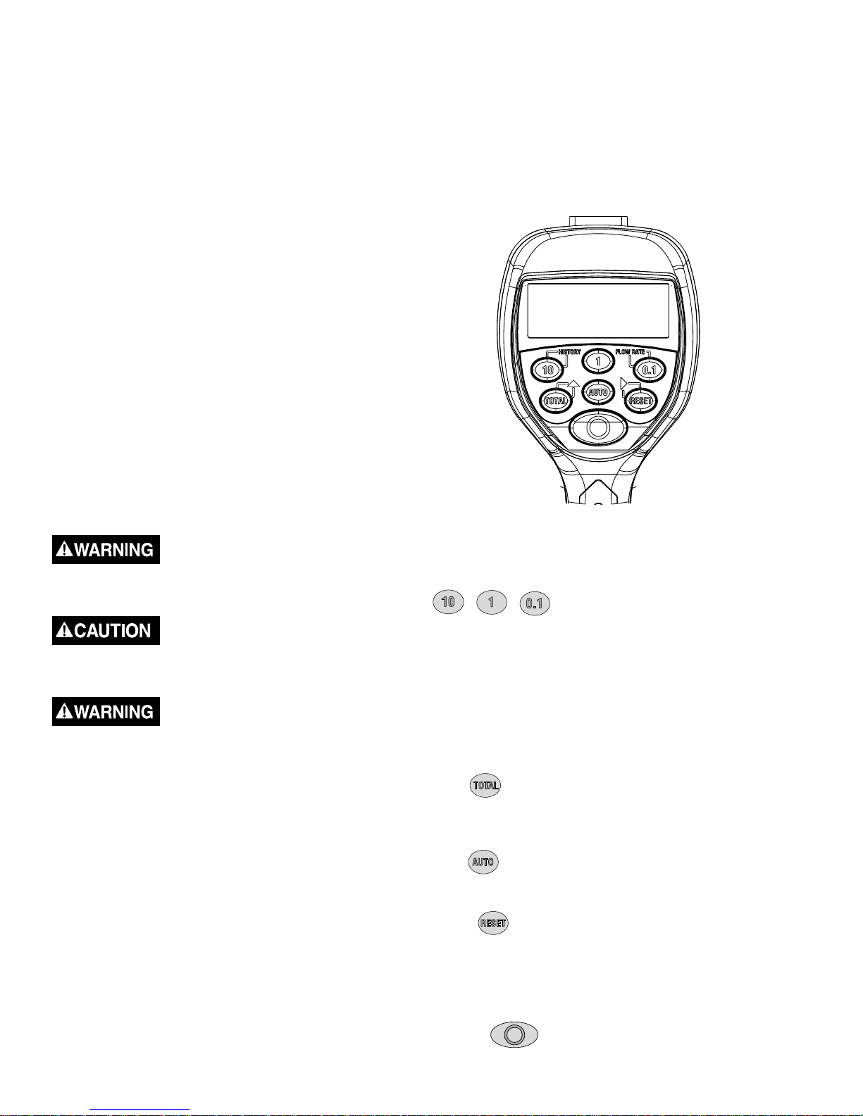
TABLE OF CONTENTS
Definitions ......................................................................2
Installation ...................................................................... 3
Operating the Meter .......................................................3
Programmin g the Meter ................................................. 4
Operational Functions ................................................... 5
Service ...........................................................................6
Dimensional Drawing ....................................................8
Specifications ................................................................. 8
Parts Drawi ng ........................................................... 9 -11
Factory Settings
Each meter is preprogrammed and calibrated at the factory.
Unless otherwise specified at the time of the order, each
meter is programmed in quarts for use with motor oil. The
meter is shipped in the Manual Mode. If you need to change
the factory settings, see page 6.
1000 psi (67 bar) Maximum Working Pressure
8 gpm (30 Lpm) Maximum Flow Rate
This Meter is designed specifically to dispense motor oils
(S.A.E. 5-50), gear oils (S.A.E. 80-240), automatic
transmission fluid, antifreeze (Ethylene Glycol) solution,
and hydraulic fluid. This meter is NOT designed to
dispense brake fluid, or windshield wiper fluid.
12. Do NOT dispense valves towards any person or any
part of the body.
13. Do NOT place hands or fingers over the end of or into
the dispense valve.
14. Comply with all local, state, and federal fire, electrical,
and safety regulations
15.Use of this product in a manner other than specified
in this manual may result in impaired operation or
damage to equipment.
SYMBOLS
This symbol is an alert to the possibility of serious injury
or death if the instructions are not followed.
This symbol is an alert to the possibility of damage to or
destruction of equipment if the instructions are not followed.
Equipment Misuse Hazard
1. This equipment is for professional use only.
2. Read all instructions, tags, and labels before
operating the equipment.
3. Use the equipment only for its intended purpose.
4. Do NOT modify or alter the equipment.
5. Do NOT leave equipment unattended while
dispensing.
6. Check equipment daily. Repair or replace worn or
damaged parts immediately.
7. Do NOT exceed the maximum working pressure level
of the lowest rated system component.
8. Use only extensions and nozzles that are designed
for use with this equipment.
9. Use only fluids and solvents that are compatible with
the equipment. Read all fluid and solvent
manufacturer’s warnings.
10. Tighten all fluid connections before operating this
equipment.
11. Do NOT stop or deflect leaks with hands, body,
gloves, or rags.
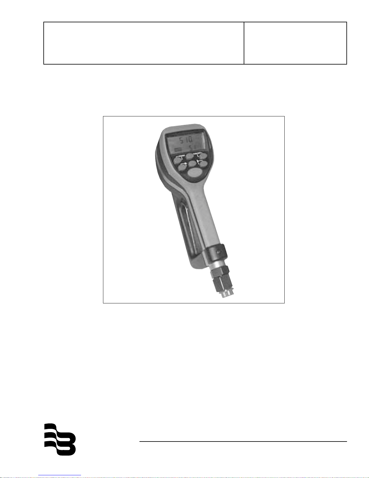
Overhead view of Display and Keypad
Keypad Buttons
In Auto and Programming Mode, used to enter the
quantity to be dispensed.
History
Used to scroll through the five previous batches during
the normal operating mode.
Flow Rate
Used to indicate the rate of flow while the fluid is being
dispensed.
Total
Used to display the accumulated total of fluid, as well as
the resettable total during normal operating mode.
Used to scroll through the menu options in the auto mode.
Auto
Used to enter and exit the auto mode to program batch
types and sizes.
Reset
Used in normal operating mode to clear the previously
programmed batch and to reset the meter. Used to reset
the resettable total after pressing the TOTAL button.
Used to advance through the programming screens in
the programming mode.
Shut-Off
Used to stop the flow through a mechanical override.
2
Page 3

Installation
Pre-Installation Procedure
1.Relieve the system pressure:
a. Turn off the power supply to the pump or close the
shutoff valve.
b. Dispense any fluid in the system into a waste
container by opening the dispense valve.
c. Open all bleed-type master air valves and fluid
drain valves in the system.
d. Leave the drain valve open until ready to
pressurize the system.
2.Close the shutoff valve.
3.Ground hoses and reels:
Grounding reduces the risk of static sparking;
ground all system components according to local,
state, and federal code. Consult the user's manual
of the pump and other system components to
ground the following:
i. Pump: follow manufacturer's recommendations
ii. Air and Fluid Hoses: use only grounded hoses
iii. Air Compressor: follow manufacturers
recommendations
iv. Fluid Supply Container: Follow the local code
Do not use Teflon® tape on pipe joints; it may cause a
loss of grounding across the joint.
Installation Procedure
1. If this is an existing installation, go directly to step 6.
Steps 2 through 5 are for flushing the system prior to
installing the meter.
2. Close fluid dispense valves at every dispense position.
3. Once the main fluid outlet valve at the pump is
closed, the air pressure to the pump motor is
properly adjusted, and the air valve is open, slowly
open the main fluid valve.
4. Place the hose end in a waste container. Make sure
hose is secure so no fluid will leak during flushing.
5. Slowly open the dispense valve and allow enough oil
to pass through to ensure that the system is clean.
Close the valve and repeat for all dispense positions.
Note: If the system has multiple dispense positions,
begin at the position farthest from the pump, and
move towards the pump.
6. Relieve the Pressure (see Relieve the System
Pressure, above).
7. Insert the metal end of the hose into the swivel
located at the end of the handle, and tighten
completely with an open ended, adjustable wrench.
Note: The threaded end of the meter will always have
female threads, so the metal end of the hose must
have male threads. Apply thread sealant to the male
end. The inlet and outlet connections are both 1/2"
NPT or 1/2" BSPP depending on meter model.
8. Thread the new nozzle onto the opposite end of the
meter and screw in tightly with an open ended,
adjustable wrench.
Installing the nozzle
9. Open all dispense position shut-off valves, and start
the pump to pressurize the system.
10. To ensure accuracy, purge all air from the fluid lines
and dispense valve before use.
Operating the Meter
Manual Mode
1. Program the meter to manual mode by selecting
option ‘0’ in the batch-programming mode. (See
Programming the Preset Batch Function)
QT.QT
..
Manual Mode
2. Pull the trigger to begin the flow.
3. When the desired amount has been pumped,
release the trigger to stop the flow. Press
reset counter display to zero.
to
Attaching the hose
3
Page 4
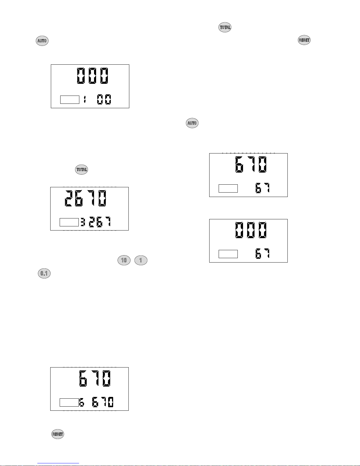
Programming the Preset Batch Function
,,
1.To enter the batch-programming mode, press and hold
the
AUTO (approx. 2 seconds.). The following screen will
appear:
button until the digit and colon appear next to
a. Press the button to toggle between the two
options, count up or count down. Press the
button to select either count up or count down
mode for all batches and to return to the
options.
QT
.
..
:
AUTO
AUTO
Auto Mode, Option 1
2.The meter is now ready to be programmed. The ‘1’
before the colon will be flashing. This is the option
icon. Option ‘0’ is for manual mode (see Manual
Mode). Options ‘1’-‘5’ are for auto batching amounts up
to 99.9 units. Different batch amounts can be stored in
each option. Option ‘6’ is for batches between 1 and
999 units. Press the
options.
:
key to cycle through the
QT
-->
.
.
-->:-->-->
QT
..
AUTO
Auto Mode, Option 3
:
,,
<--<--
Note: In the count-up option, the meter counts up to the
preprogrammed batch amount. In the count down option,
the meter counts from the programmed batch amount
down to zero. (Batch #6 will always be in the countdown
mode.)
5.Once finished programming the batch sizes, press the
button to exit this option. The screen will flash,
and then, if the meter is in the count down mode, the
desired batch size will appear on the display. If the
meter is in count up mode, the display will show zeros.
QT
.
..
AUTO
AUTO
Count Down Mode
QT
.
.
<--<--
QT
..
3.When the desired option appears on the screen,
change the batch size by pressing the
and buttons.
a. Pressing the 10 button will increase the
batching amount in increments of 10 units.
b. Pressing the 1 button will increase the batching
amount in increments of 1 unit.
c. Pressing the 0.1 button will increase the
batching amount in increments of 0.1 units.
Note: When programming in option 6, the 10 button will
increase the batching amount in increments of 100,
whereas the 1 button will increase the batching amount
in increments of 10 units. The 0.1 button will increase
the batching amount in increments of 1 unit.
AUTO
Auto Mode, Option 6
:
,
QT
<--<--
AUTO
Count Up Mode
.
-->
4.Press the
arrows will flash in the display.
key and the count up/ count down
4
Page 5

Batch (Auto) Mode
1.Program the meter to auto mode using option 1-6 in
the batch-programming mode. (See Programming the
Batch Function)
2.Pull the trigger to begin the flow. The valve will
automatically lock in place, even though the trigger will
fall back to the closed position. The flow will
automatically shut off when the desired batch size has
been dispensed.
Flow Rate
This option allows the user to see the instantaneous rate
at which oil is flowing through the meter.
While oil is flowing through the meter, press and hold the
/ FLOW RATE button, and the rate of flow will
appear in the bottom right corner of the display. As long
as the button is held down, the flow rate will remain on
the display. Releasing the button will return the display to
the normal operating screen.
The valve will always lock in the maximum open position.
Note: At any time during the operation of the meter, the
flow may be stopped by pressing the red
button.
This will mechanically close the valve, stopping the flow.
Batching may be resumed by pulling the trigger.
3.The user has the option to top off at the end of the batch.
To top off the tank, simply pull the trigger to begin the flow
and release when the desired amount has been
pumped. If in count down mode the additional amount
will be shown on the display. If in count up mode, the
additional amount will be added to the total amount
dispensed.
4.Press the
meter. It is now ready for the next batch.
Do NOT press before topping off. The meter will
begin a new batch.
button when finished to reset the
Normal Operating Mode Functions
History
This option allows the user to review the previous five
batches dispensed with meter.
1.Press and hold the
five previous batches. The batches will be displayed on
the screen one at a time, starting with the most recent,
and cycling through to the oldest. The batches will
continue cycling as long as the HISTORY button is held
down.
The display will automatically return to the normal
operating screen 2 seconds after releasing the
HISTORY button.
/ HISTORY button to view the
QT
.
GPMGPMGPM
,,
Flow Rate Function
Note: The flow rate can only be displayed if fluid is flowing
through the meter.
Total
This option allows users to see the accumulated total as
well as the resettable total.
Press and hold the
operating mode to see the accumulated total. Continue
holding and after three seconds the screen will change to
the resettable total, which displays the total fluid
dispensed since the resettable total was last set back to
zero.
Press the
to set the resettable total back to zero. Release the
button to return to the normal operating screen.
button while viewing the resettable total
button while in normal
Note: The accumulated total cannot be reset, unless the
user changes from English units to metric units or from
metric to English units. (See Changing Factory Settings.)
L
RESET TOTAL
Total Function
..
HISTORYHISTORY
History Function
Note: The history cannot be era s ed , unless the user
changes from English units to metric units or from metric to
English units. (See Changing Factory Settings.)
QT
5
Page 6

Mechanical Override
In case of an emergency or to interrupt a batch, the meter
is equipped with a mechanical override. This option
automatically closes the valve in the meter, stopping the
flow immediately. Batching can be continued after an
override, even if the meter is in the middle of a
programmed batch.
Changing Factory Settings
Factory Settings
Each meter is preprogrammed and calibrated at the
factory. Unless otherwise specified at the time of the
order, each meter is programmed in quarts for use with
motor oil.
Press the red
override. This can only be used when the valve is open.
(The red stop button may require considerable force to
activate.)
button to activate the mechanical
Service
Changing the Battery
When the batteries need to be changed, a progression of
warnings will appear on the screen.
1.First warning: the Low Battery Icon will appear in the
lower left corner of the display. This means that the
batteries are low and need to be changed within one
week after the icon first appeared.
QT
.
..
+
+ -+ +
-
-
2.Second warning: The AUTO function will shut off and
the auto icon will disappear. This means the battery
power is too low to run the auto function. The meter
can still run in manual mode.
3.Third Warning: The screen goes blank. This means
there is no power left. The display cannot be run.
However the meter will still allow fluid to pass through
when the valve is opened, but it will not measure flow.
• The battery compartment is located on the underside of
the trigger guard. Unscrew the two screws located under
the guard and remove the battery cover to expose the
batteries.
• Replace the old batteries. This meter takes 4 AAA
alkaline batteries. Replace the cover and the screws
when finished. Note battery polarity markings inside
battery compartment cover.
QT.QT
1. Press
To enter the programming mode, press and hold the
<PROGRAMMING> key located in the access hole
under the meter for 2 seconds. (See picture bel o w )
Location of access hole for PROGRAMMING Key.
After the screen flashes, it will display the scale factor and
units of measurement.
to wake up the meter if screen is blank.
Use a 5/32"
Allen wrench
or similar
blunt tool
QT.QT
.
Initial Programming Screen
Programming the Units
This meter comes with the option to choose 4 different
units of measure. Unless otherwise specified at the time
of the order, each meter is programmed in quarts for use
with motor oil. The ‘Qt' will be flashing on initial start-up.
1. Toggle the four options (‘L’, ‘QT’, ‘GAL’, ‘PNT’) by
pressing the button.
2. When the desired option is on the screen, press the
button to advance. The units of measurement
icon will stop flashing and the first digit of the scale
factor will begin flashing.
• Dispose of used batteries properly according to local
regulations.
Make sure to securely replace the rubber o-rings
surrounding the battery cap and screws to prevent liquid
from leaking into the battery compartment. The o-rings are
reusable indefinately, however new o-rings can be
purchased. See spare parts drawing on page 10.
Changing the batteries will not affect any of the
programmed values, history, or totals.
Note: If the ‘L’ units have been selected, the decimal
point will begin to flash. The user now has the option to
change the decimal point to either a period or a comma.
To do this, press the
button. Press the button
to advance to the scale factor screen.
Changing the units of measurement from metric to English,
or from English to metric will clear the accumulated total,
resettable total, and all five histories.
6
Page 7

Recalibrating the Meter
The Scale factor is used to adjust the accuracy of the
meter. The scale factor will be set at the factory for oil. The
primary use for the recalibration function is if the user
wants to batch fluids with a viscosity other than 10W oil.
If the fluid has a lower viscosity, more fluid can slip past
the gears without being detected. Changing the scale
factor can adjust the meter to compensate for that loss
The meter multiplies each pulse by this number to correct
the accuracy when it converts to the specified units, so the
reading on the dial is always correct.
For an approximate scale factor for fluids of different
viscosities, consult the following chart:
Type of Fluid Viscosity (cp) Scale Factor
Water /A n ti -F r ee ze 5 0.9580
Anti-Freeze 18 0.9930
Automatic Transmission Fluid 80 0 . 9980
Motor Oil 140 0.9960
Benz 80W-90 400 1.0020
Mobil 80W-90 450 1.0004
SAW 50W 900 1.0040
140WT 1800 1.0070
,
Scale Factor Screen
3.Press to advance to the next number in the scale
factor.
4.Repeat steps 2 and 3 for all five digits in the scale factor.
L
Note: All digits can be scrolled between 0 and 9 except
the first, which can only be scrolled from 0 to 1.
5.When finished setting the scale factor, press the
button and the scale factor and units measurement
screen will be replaced with the pulse delay screen:
(Unless otherwise specified at the time of the order, each
meter is programmed in quarts for use with motor oil.)
Note: The original meter scale factor is written inside of
the meter when calibrated at the factory. It may have been
revised after field installation. Use scale factor shown on
display, not the lavel.
To view the current program scale factor, do the following:
1. Press and hold the
2. Then, press and hold the
For an absolute scale factor, perform the following test:
Run a pre-measured batch of fluid through the meter. If the
meter is programmed to batch 4.200 quarts, and it batches
the entire amount but only reads 4.000 quarts, then the scale
factor needs t be adjusted. Divide the quantity delivers (4.2)
by the quantity dispensed (4.0) to get the error factor (1.05)
To calculate the new scale factor:
If existing scale factor is 1.0123, then calculation would be:
1.0123 (existing scale factor) x 1.05 (error factor) = 1.0629
(new scale factor)
Change the scale factor:
button.
button.
Setting the Pulse Delay Factor
The Pulse Delay Factor is used to correct for fast flow
rates by closing the valve in the meter between one and
five pulses sooner than the selected value. The meter is
factory programmed with a pulse delay factor of 0.
Pulse Delay Screen
Advance through all five scale factor digits by pressing the
button. The above screen will now be displayed.
1.The 'PS-' will be followed by a flashing zero. The zero is
the initial setting of the pulse delay factor
2.Scroll between settings (0 to 5) by pressing the
button.
3.When finished selecting the pulse delay factor, press
and the displa y will return to the scale factor screen.
Press <PROGRAMMING> key to enter the programming
mode, and the
mode.
1. The first digit of the scale factor will be flashing.
2. Press the
button to advance through the units
button to scale through the numbers.
4.When finished programming these options, press the
<PROGRAMMING> key and hold it until the screen
flashes three times then goes blank. Press the
button to return to the normal operating screen.
7
Page 8

11.00"
3.50"
6.00"
SPECIFICATIONS
English Metric
Maximum Flow * 8 gpm 30 lpm
Minimum Flow * 0.25 gpm 1 lpm
Operating Pressure (Maximum) 1000 psi 67 bar
Operating Pressure (Minimum) 5 psi .35 bar
Operating Temperature (Maximum) 120° F50° C
Operating Temperature (Minimum) 20° F- 5° C
Accuracy (Non-Approved Version) +/- 0.5% +/- 0.5%
Accuracy (Approved Version) +/- 0.4% +/- 0.3% (1 to 10 lpm)
5-Digit LCD Display, 10 mm High x 5 mm Wide Quarts, Pints, Gallons Lite r s
Inlet and Outlet Connections ½” NPT ½” BSPP
* Tested with DTE-25 motor oil at ambient temperature. Min.-Max. flow range will vary with fluid viscosity.
8
Page 9

3
4
ab
ITEM # PART DESCRIPTION PART NUMBER
1 Top Case with Screws 64103-002
2 Keypad 63802-001
3 PCB Assembly, Non-Approved with Screws 64103-001
4a Bare Meter, NPT 63897-001
4 b Bare Meter, BSPP 63897-002
9
Page 10

5
ITEM # PART DESCRIPTION PART NUMBER
1 Battery Door with Screws 64103-004
2 Bottom Case with Screws 64103-003
3 Detent Ball 63841-001
4 Solenoid 63879-001
5 O-Ring, Battery Door 55300-043
6 O-Ring, B atter y Compartme nt Scr ew 55300-006
10
Page 11

ITEM # PART DESCRIPTION PART NUMBER
1 Valve Assembly 63997-001
2 Screw, Sems Type 63253-001
3 Housing Cover 63810-001
4 O-Ring 55300-035
5 Gear Service Kit with O-Ring 62896-001
6 Trigger Assembly 64103-005
11
Page 12

BadgerMeter,Inc.
P.O. Box 245036 Milwaukee, WI 53224-9536
Telephone: (414) 355-0400
®
Fax: (414) 355-7499
Due to continuous research, product improvements and
enhancements, Badger Meter reserves the right to change
product or system specifications without notice, except to the
extent that an outstanding bid obligation exists.
Copyright© 2001 Badger Meter, Inc.
All rights reserved.
 Loading...