

Page 1
Signal Wiring
F6600 / F6650 and F6700 / F6750 Series Displays
WIRING OVERVIEW
Electrical connections are made via screw-clamp terminals located on the back of the display. All conductors should conform to the meter’s
voltage and current ratings. All cabling should conform to appropriate standards of good installation, local codes and regulations. It is
recommended that power supplied to the meter (DC or AC) be protected by a fuse or circuit breaker.
When wiring the display, compare the numbers embossed on the back of the display case against those shown in the wiring drawings for
proper wire position.
Each terminal can accept up to one #14 AWG (2.55 mm) wire, two #18 AWG (1.02 mm), or four #20 AWG (0.61 mm).
1. Strip the wire, leaving approximately 0.3 inches (7.5 mm) bare lead exposed (stranded wires should be tinned with solder).
2. Insert the lead under the screw-clamp terminal.
3. Tighten the screw-clamp until the wire is secure.
4. Pull the wire to verify tightness.
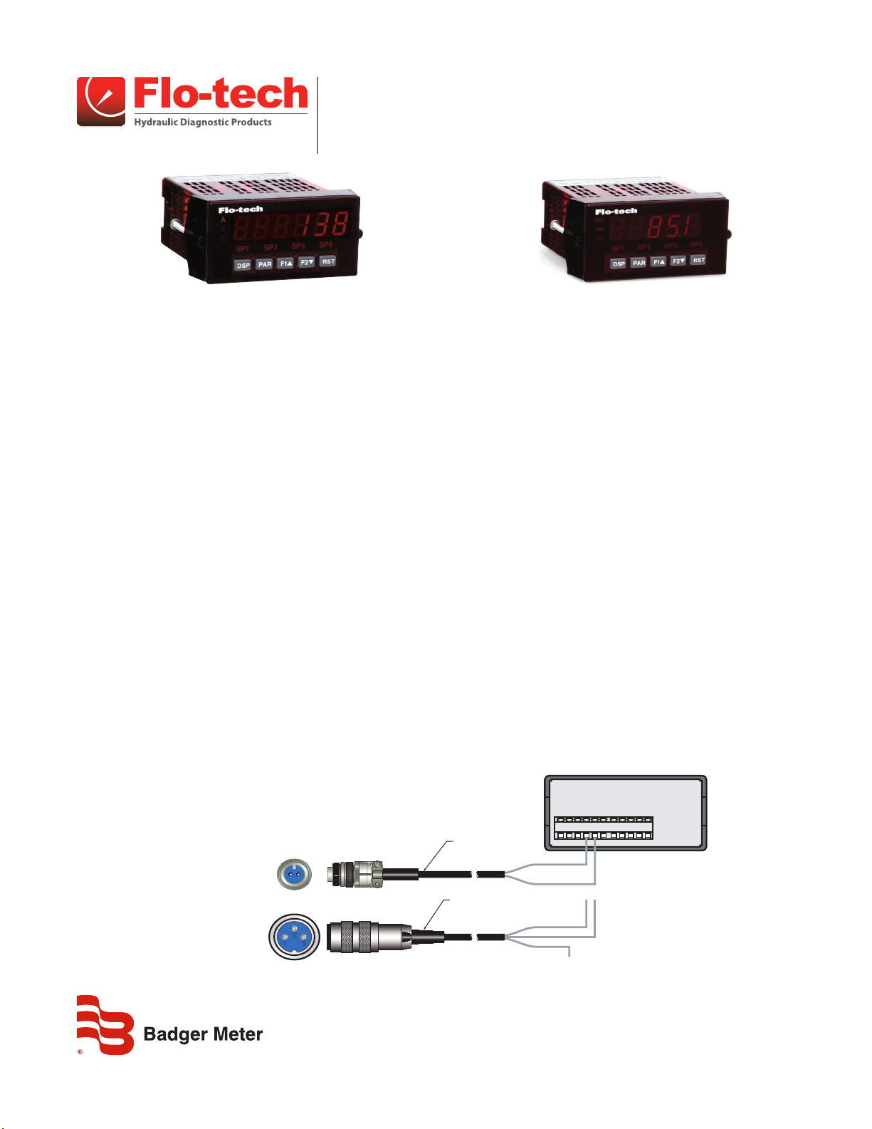
WIRING THE F6600 / F6650 SERIES DISPLAYS
The frequency signal from the Flo-tech FSC, FSB, and FSD series turbines is connected to the display using one of the
F2832 series cables. The Flo-tech Ultima sensor is connected using the F6234 series cables.
FSB, FSC*, and FSD Sensors
Connect the BLUE wire of the F2832 cable to terminal 5 (INPUT A) and the YELLOW wire to terminal 4 (COMM) on the F6600 series display.
See Figure 1.
* Some require the use of the F5140 K-Factor Scaler to ensure adequate signal strength to the display.
Ultima Sensors*
Connect the RED wire of the F6234 cable to terminal 5 (INPUT A) and the BLACK wire to terminal 4 (COMM) on the F6600 series display. See
Figure 1. The WHITE wire is not used.
* Some require the use of the F5140 K-Factor Scaler to ensure adequate signal strength to the display.
F6600 / F6650
Series Display
COMM
INPUT A
INPUT B
+
-
+
A - + (BLUE)
B - - (YELLOW)
1 - N/C (WHITE)
2 - - (BLACK)
3 - + (RED)
Top of
F2832 Cable
B A
321
Top of
F6234 Cable
CABLE ASSEMBLY
F2832-6 6 ft (1.8 m)
F2832-15 15 ft (4.6 m)
CABLE ASSEMBLY
F6234-6 6 ft (1.8 m)
F6234-15 15 ft (4.6 m)
(WHITE) N.C.
Figure 1: Flo-tech frequency output wiring
1 2 3 4 5 6 7 8 9 10 11
(YELLOW) -
(BLUE)
(BLACK)
(RED)
SGN-UM-00979-EN-06 (June 2014)
User Manual
Page 2
Signal Wiring, F6600 / F6650 and F6700 / F6750 Series Displays
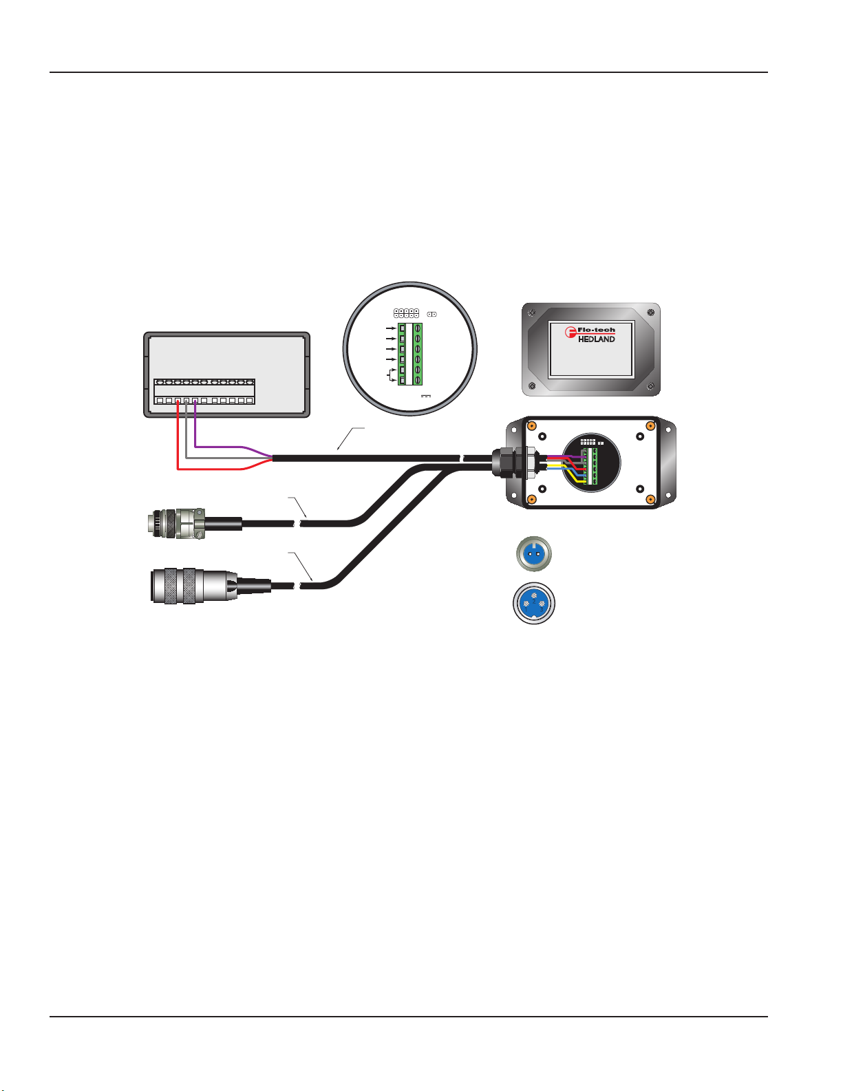
WIRING THE F6600 / F6650 SERIES DISPLAYS
WITH F5140 KFACTOR SCALER
The Flo-tech FSC-375, F6202-F, and F6222-F turbines require the F5140 K-Factor Scaler to amplify the millivolt sensor output for transmission
to the F6600 series display. The turbines produce a low level signal so it is important to keep the F5140 K-Factor Scaler as close to the flow
sensor as possible. Close proximity will minimize signal interference and help eliminate erratic readings.
1. Feed the terminal end of the F2832 or F6234 cable through the wire bushing on the F5140. Insert the three-wire (customer supplied)
cable that will be used to bring power and return the output signal to the F6600 series readout. Tighten the wiring bushing.
2. Connect the BLUE wire from the F2832 or the RED wire from the F6234 cable to terminal 5 of the F5140 K-Factor Scaler. Connect the
YELLOW wire from the F2832 or the BLACK wire from the F6234 cable to terminal 6 of the F5140 K-Factor Scaler. See Figure 2.
PROGRAMMING
- OUTPUT
+ OUTPUT
- VIN
+ VIN
TURBINE
PICK UP
3 Wire Cable
PORT
1 2 3 4 5 6
K-FACTOR SCALER
INPUT 8.5 - 30 VDC
MAX INPUT CURRENT: 18 mA
INTERNAL
3.6K PULL-UP
RESISTOR
JUMPER
by ®
K-FACTOR SCALER
F5140
S.N. 12345
2200 South Street Racine, WI 53404 U.S.A.
Phone: 262-639-6770 Fax: 262-639-2267
www.hedland.com
1 2 3 4 5 6
F6600 / F6650
Series Display
COMM
INPUT A.
INPUT B
+12 VDC
1 2 3 4 5 6 7 8 9 10 11
Output
Common
+ 12 VDC
8.5 - 30 VDC
(Customer Supplied)
CABLE ASSEMBLY
F2832-6 6 ft (1.8 m)
F2832-15 15 ft (4.6 m)
CABLE ASSEMBLY
F6234-6 6 ft (1.8 m)
F6234-15 15 ft. (4.6 m)
Top of
F2832 Cable
Top of
F6234 Cable
B A
321
A - + (BLUE)
B - - ( YELLOW)
1 - N/C (WHITE)
2 - - (BLACK)
3 - + (RED)
Figure 2: Flo-tech frequency output wiring using F5140 K-factor scaler
4. Connect one of the wires from the customer-supplied cable to terminal 4 (+VIN) of the F5140 and note the wire color. Connect the other
end of this wire to terminal 3 (+12V DC) of the F6600 series display.
5. Connect one of the wires from the customer-supplied cable to terminal 2 (+OUTPUT) of the F5140 and note the wire color. Connect the
other end of this wire to terminal 5 (INPUT A) of the F6600 series display.
6. Connect the remaining wire from the customer-supplied cable to terminal 1 (-OUTPUT) of the F5140. Connect the other end of this wire
to terminal 4 (COMM) of the F6600 series display.
OTE:N A jumper wire is required between terminals 1 and 3 of the F5140.
Page 2 June 2014SGN-UM-00979-EN-06
Page 3

User Manual
WIRING THE F6700 / F6750 SERIES DISPLAYS
ACTIVA Flow Sensors, FS Series Flow Sensors and F6100 Series Sensor Arrays Using the
Intelligent Frequency Converter (IFC) Option
4…20 mA Output
The F6557 cable is a five-pin, three-wire cable used to connect the IFC sensors to the F6700 series displays. Only two of the three wires in
the cable are used.
1. Connect the RED wire of the F6557 cable to terminal 6 (+24 V EXC) on the F6700 series display. See Figure 3.
F6700 / F6750
Series Display
20 mA
COMM.
+24 V EXC.
1 2 3 4 5 6 7 8 9 10 11
(RED) + Loop
(BLACK) - Loop
(WHITE) N.C.
4
5
Top of
F to I Converter
3
2
Pin 1 = + 4 - 20 mA (Sink) - RED
Pin 2 = - 4 - 20 mA (Source) - BLACK
Pin 3 = N/C - WHITE
Pin 4 = N/C
Pin 5 = N/C
1
CABLE ASSEMBLY
F6557-6 6 ft (1.8 m)
F6557-15 15 ft (4.6 m)
Shield
Figure 3: Flo-tech IFC flow sensor wiring
2. Connect the BLACK wire of the F6557 cable to terminal 4 (20 mA) on the F6700 series display.
3. Connect the SHIELD wire of the F6557 cable to terminal 4 (20 mA) on the F6700 series display.
0…5 Volt Output
The F6557 cable is a five-pin, three-wire cable used to connect the IFC sensors to the F6700 series displays. Only two of the three wires in
the cable are used.
1. Connect the RED wire of the F6557 cable to terminal 6 (+24 V EXC) on the F6700 series
display. See Figure 4.
3
4
5
Top of
F to V Converter
2. Connect the BLACK wire of the F6557 cable to terminal 3 (10 V) on the F6700 series display.
3. Connect the WHITE wire of the F6557 cable to terminal 5 (COMM) on the F6700 series display.
2
Pin 1 = + 24V DC - RED
Pin 2 = 0-5 VDC Output - BLACK
Pin 3 = Common - WHITE
Pin 4 = N/C
Pin 5 = N/C
1
Figure 4: Flo-tech IFC flow sensor wiring
CABLE ASSEMBLY
1 2 3 4 5 6 7 8 9 10 11
F6557-6 6 ft (1.8 m)
F6557-15 15 ft (4.6 m)
F6700 / F6750
Series Display
10 V
COMM.
+24 V EXC.
(RED) + V
(WHITE) Common
(BLACK) 0-5 VDC Out
Page 3 June 2014 SGN-UM-00979-EN-06
Page 4

F6301 Pressure Sensors and F6310 Temperature Sensors
The F6234 cable is a three-pin, three-wire cable used to connect either a pressure or temperature sensor to the F6700 series displays. Only
two of the three wires in the cable are used.
1. Connect the RED wire of the F6234 cable to terminal 6 (+24 V EXC) on the F6700 series display. See Figure 5.
1 - Case Ground
2 - 4 - 20 mA Out
123
3 - +VDC
Top of
Temperature Sensor
1 - N/C
2 - 4 - 20 mA Out
123
3 - +VDC
Top of
Pressure Sensor
CABLE ASSEMBLY
F6700 / F6750
Series Display
20 mA
COMM.
+24 V EXC.
1 2 3 4 5 6 7 8 9 10 11
F6234-6 6 ft (1.8 m)
F6234-15 15 ft (4.8 m)
(WHITE) N.C.
(RED) + Loop
(BLACK) - Loop
Figure 5: Flo-tech pressure and temperature sensor wiring
2. Connect the BLACK wire of the F6234 cable to terminal 4 (20 mA) on the F6700 series display.
HEDLAND Flow Transmitter
The HN100542 cable is a four-pin, four-wire cable used to connect the HEDLAND flow transmitters to the F6700 series displays. Only two of
the four wires in the cable are used.
1. Connect the RED wire of the HN100542 cable to terminal 6 (+24 V EXC) on the F6700 series display. See Figure 6.
F6700 / F6750
Series Display
20 mA
COMM.
+24 V EXC.
CABLE ASSEMBLY
HN100542-15
(WHITE) N.C.
1 2 3 4 5 6 7 8 9 10 11
(RED) + Loop
(BLACK) - Loop
(Green) N.C.
Figure 6: HEDLAND flow transmitter wiring
2. Connect the BLACK wire of the HN100542 cable to terminal 4 (20 mA) on the F6700 series display.
After the signal wiring has been completed the F6700 series display can then be mounted in the panel and power wiring applied. See the
specific F6700 series display manual for power wiring and additional setup requirements.
Control. Manage. Optimize.
Flo-tech and Hedland are registered trademarks of Badger Meter, Inc. Other trademarks appearing in this document are the property of their respective entities. Due to continuous
research, product improvements and enhancements, Badger Meter reserves the right to change product or system specications without notice, except to the extent an
outstanding contractual obligation exists. © 2014 Badger Meter, Inc. All rights reserved.
www.badgermeter.com
The Americas | Badger Meter | 4545 West Brown Deer Rd | PO Box 245036 | Milwaukee, WI 53224-9536 | 800-876-3837 | 414-355-0400
México | Badger Meter de las Americas, S.A. de C.V. | Pedro Luis Ogazón N°32 | Esq. Angelina N°24 | Colonia Guadalupe Inn | CP 01050 | México, DF | México | +52-55-5662-0882
Europe, Middle East and Africa | Badger Meter Europa GmbH | Nurtinger Str 76 | 72639 Neuen | Germany | +49-7025-9208-0
Europe, Middle East Branch Oce | Badger Meter Europe | PO Box 341442 | Dubai Silicon Oasis, Head Quarter Building, Wing C, Oce #C209 | Dubai / UAE | +971-4-371 2503
Czech Republic | Badger Meter Czech Republic s.r.o. | Maříkova 2082/26 | 621 00 Brno, Czech Republic | +420-5-41420411
Slovakia | Badger Meter Slovakia s.r.o. | Racianska 109/B | 831 02 Bratislava, Slovakia | +421-2-44 63 83 01
Asia Pacic | Badger Meter | 80 Marine Parade Rd | 21-04 Parkway Parade | Singapore 449269 | +65-63464836
China | Badger Meter | 7-1202 | 99 Hangzhong Road | Minhang District | Shanghai | China 201101 | +86-21-5763 5412 Legacy Document Number: FTLIT-553-5
 Loading...