


Bermuda

P/N 95-0735
Above Ground Pool Assembly & Installation
OVAL SLAT WALL POOL
Buttress Free and Traditional Buttress
WA R N I N G :
THIS POOL IS NOT DESIGNED FOR DIVING OR JUMPING.
DANGEROUS INJURY CAN RESULT-SHALLOW WATER!!!
Follow All Safety and Maintenance Instructions
Your pool is designed for years of pleasurable, safe family fun. But, when
used incorrectly, a swimming pool can be dangerous. To insure your pool is
used safely you must observe the following safety precautions:
Do not dive!-Do not jump!- No rough play!- No running or pushing!
Do not walk on the top rail. It can be slippery and is not a walkway.
Be sure to install all safety labels provided with your pool according to the
instructions.
Keep a safety rope 1/4” by 50’ with a flottation buoy with an outside diameter of
15”. Have accessible in a prominent area by your pool.
Post near all entrances to pool area; a list of telephone numbers of the:
• Nearest available police • Nearest ambulance service
• Nearest available fire department • Nearest available hospital
• Nearest available rescue unit • Nearest available physician
• 911 emergency number if available
Provide fencing or enclosure which is independent of the house as a closure
around the entire pool area. The fencing must be made of durable material, a
minimum of 4’ in height from ground level and with closures with self-latching
locks, to make pool inaccessible to toddlers and uninvited guests. Make sure
gate is always closed. Be sure to follow local building code requirements for load
capacity and fencing if using an aftermarket or homebuilt deck. You must make
sure all fence and barriers are in working order so that pool is always protected.
Check with your local town for any special laws in your locale.
Never drink alcoholic beverages or use any intoxicants which could hinder your
judgment and reflexes.
Never use pool alone. All children must be supervised continuously.
Do not use pool if bottom is not clearly visible: At night, sufficient lighting must
be available. It is the pool owners sole responsibility to provide adequate
lighting for pool bottom, safety signs and walkways, which exceeds minimum
standards of the IES of North America.
Do not climb, stand or sit on any pool structure or the filter system. Components
such as the filtration system, pumps and heater must be positioned so as to
prevent their being used as a means of access to the pool by young children.
Be sure that all toys, chairs and tables or similar objects that a young child could
climb on be at least four feet (4’) from pool.
Do not use pool during electrical or rain storms.
See available National Spa and Pool Institute (NSPI), publications for more tips on pool safety.
WA R N I N G :
DO NOT AFFIX
ANY OTHER PRODUCTS
MADE BY OTHERS
TO YOUR POOL
SUCH AS
BUT NOT LIMITED TO ,
DECKS AND SLIDES!
,
IMPORTANT NOTICE!
READ BEFORE INSTALLATION
ENCLOSED IN FRAME CARTON IS SAFETY
ENVELOPE. THE SAFETY STICKERS MUST
BE INSTALLED AS PER FOLLOWING
INSTRUCTIONS. FAILURE TO PROPERLY
INSTALL WARNING LABELS WILL VOID
WARRANTY. FAILURE TO MOUNT THESE
SAFETY LABELS MAY SUBJECT Y OU TO
SUBSTANTIAL LIABILITY IN CASE OF INJURY.
THESE WARNINGS ARE NOT TO
BE REMOVED UNDER ANY CIRCUMSTANCES! IF THEY BECOME
DISCOLORED OR FALL OF, F
PLEASE REQUEST REPLACEMENTS WHICH WILL BE SENTA T
NO CHARGE.
SIGN MUST BE PLACED
ON WALL NEXT TO ENTRY
TO POOL
SIG N TO BE PLA CED ON
LIN ER ABOV E WATER LINE
OPPO SITE ENTRY TO POO L

Notes
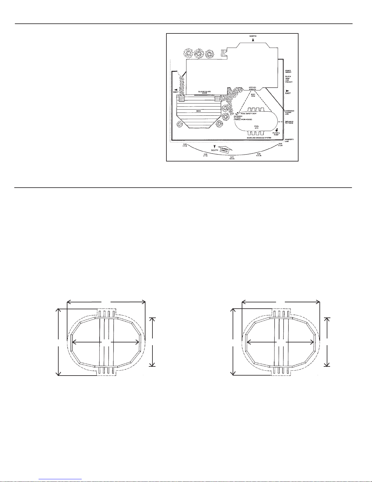
This document addresses the assembly of a variety of standard size oval pools. However, even if you have purchased
a tear-drop style pool, the assembly process is still basically the same. Your dimensions though, will be different.
Please refer to the images below for the tear-drop style pool dimensions.
328 (27 FT. 4 IN.)
TRANSITION
TOP WALL RIM
2 PCS, 36 1/2"
CURVED END
TOP WALL RIM
3 PCS, 35 1/4"
TEAR-DROP POOL
12’ DIA. x 18’ DIA.
x 27’ 4” LONG
CURVED END
BOTTOM WALL RIM
144
(12 FT)
3 PCS, 38"
STRAIGHT SIDE
BETWEEN UPRIGHTS
TOP & BOTTOM WALL RIM
12 PCS, 37 1/2"
TRANSITION
BOTTOM WALL RIM
4 PCS, 39"
CURVED END
TOP WALL RIM
8 PCS, 47 1/4"
CURVED END
BOTTOM WALL RIM
8 PCS, 50"
221
(18 FT. 5 IN.)
BEAM SLAT INSTALLED
ON BOTH SIDES OF EACH
UPRIGHT ON THE CURVED
SIDES OF THE OVAL POOL
CURVED END
TOP WALL RIM
5 PCS, 46 1/4"
TEAR-DROP POOL
15’ DIA. x 21’ DIA.
x 33’ LONG
CURVED END
BOTTOM WALL RIM
183
(15 FT. 3 in.)
5 PCS, 49"
STRAIGHT SIDE
BETWEEN UPRIGHTS
TOP & BOTTOM WALL RIM
16 PCS, 37 1/2"
397 (33 FT. 1 IN.)
CURVED END
BOTTOM WALL RIM
8 PCS, 50"
CURVED END
TOP WALL RIM
8 PCS, 47 1/4"
(21 FT. 3 IN.)
BEAM SLAT INSTALLED
ON BOTH SIDES OF EACH
UPRIGHT ON THE CURVED
SIDES OF THE OVAL POOL
255
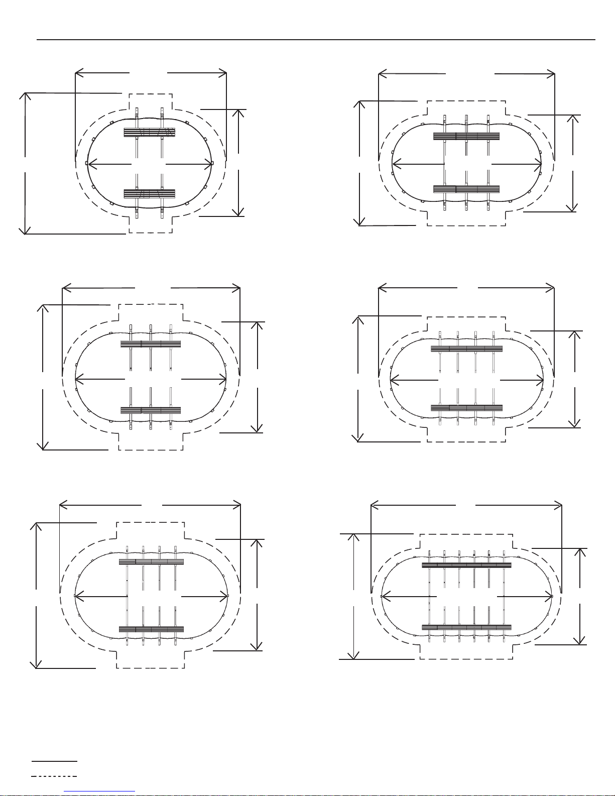
BUTTRESS-FREE POOL SIZES
17'
19'
17'
12 x 17
28' 6"
12'
17'
25' 10.5"
23' 10.5"
12 x 24
32'
12'
20' 4"
23' 4"
26' 6"
15 x 26
35'
33'
15' 2”
18' 2"
20' 4"
23' 4"
30'
15 x 30
42'
40'
15' 2"
18' 2"
18 x 33
Note: All above diagrams are for Buttress-Free oval pools. If you have a traditional Buttress oval pool, you will need
to add 3 feet to the width of the space needed for installation. The length measurement will not change.
Actual size of pool.
Space needed for installation.
18 x 40

INTRODUCTION:
Congratulations on becoming the owner of a new above ground swimming pool. This is the instruction packet
for installing your swimming pool. The following are some helpful hints that you should take into consideration
before installing your pool.
1) Read through the entire instruction booklet before you begin. This will enable you to find out exactly what is
involved with installing your swimming pool before you begin. While you are going through the instructions,
please be aware that all of the diagrams are representative of a 15' x 30'/18' x 33' pool. If you have a different
size pool you will find that your pool has a different number of uprights than the ones in the diagrams.
2) DO NOT AT TEMPT INSTALLATION IN WINDY OR GUSTY WEATHER. This will not only make
installation more difficult, it may result in damage to your pool before it is completely installed.
3) Although we have broken down the installation into many simple steps, you will probably find that Steps 1
and 2 will be the most labor intensive and time consuming steps. Once you have completed those two steps
you should find that the rest of the installation moves along much more quickly.
4) Please be sure to review all safety material and local codes before beginning your installation. There is a yellow
safety envelope packed with your pool. This envelope contains safety material and warning stickers to be
placed on your pool. If you are missing any of these items please contact your dealer or the factory to obtain it.
The warranty is void if all safety precautions are not followed.
5) In the event that you need to make a warranty claim, it is important to know the size and model of your
swimming pool in order to expedite the handling of your claim. Please fill in the information below and keep
for your records. All of this information can be found on the labels attached to the cartons your pool is packed in.
NAME OF POOL:
SIZE OF POOL:
DATE OF PURCHASE:
NAME OF POOLWALL:
NAME OF LINER:
6) Make sure you have the necessary tools and materials before beginning your installation.
Below is a list of the tools and materials needed.
- Shovel - Carpenters level and/or transit (Optional)
- Tape measure - Patio Blocks (2" x 8" x 16")
- Phillips head screwdriver - Box cutter (Razor blade)
- Duct tape - Tamp
- Sand - 5/16” wrench
- Filter - 1/4" wrench
- Skimmer/Return fitting
POOL LOCATION:
Do not locate pool over underground lines,
septic tanks, under electrical lines, near hazardous
structures, or out of local code restrictions. It is
essential that the area selected for your pool has
a level and firm base. Do not assemble your pool
on asphalt, tar or oil base surfaces. Avoid areas
with sharp objects, or ground treated with weed
killer or other chemicals. Also avoid areas where
nut grass, Bermuda grass or bamboo grass grows,
as they can grow through your liner. Grass must
be removed. Do not place components such as
filters, pumps, and heaters in a way that they can
Sample
*BE SURE TO AVOID:
-All electrical wires
-All gas lines
-Septic tanks
-Cesspools
-Dry wells
-Tree roots/stumps
-buried debris(trees,
building material, etc.)
-sudden slopes within 6’
of pool area
be used as a means of access to pool by young
children. Be sure to follow all local building codes
and obtain all building permits required for your area.
Fig. 1
STEP 1 – PREPARING THE SITE:
Refer to the "True Size" diagram on the second page to see the dimensions of your swimming pool. Once you
have these measurements and have chosen a site to install your pool, mark or outline the ground where the pool
will be going using spray paint or some other marking agent. Please keep in mind that you will need some extra
room to work. Be sure to account for the space that the side supports extend out on each side of an oval pool.
The strap end channel extends out 37" from the wall of the pool on each of the two straight sides of a Traditional
Buttress Oval. If you have a Buttress-Free Oval Pool, the strap end channel extends only 19" out from the
wall on each side. Refer to the "Actual Size" chart for further clarification.
For example, a 15x30 oval should have the following space in order to install the pool.
Traditional Buttress Oval: Buttress-Free Oval:
32'
23'4"
Fig. 2 Fig. 2A
*Once you have the appropriate area marked out, remove any sod that is in the area. Also be sure to avoid all electrical wires,
gas lines, septic tanks, cesspools, dry wells, tree roots, stumps, buried debris, and sudden slopes within 6’ of the pool area.
30'
15 x 30
15'2"
20'4"
32'
30'
15 x 30
15'2"

STEP 2 – LEVELING:
Once you have designated the space for installation, and have cleared away the sod in that area, you can begin
to level the ground. The ideal tool for doing this is a transit. If you do not have access to a transit, use a long
board (be sure that the board is perfectly straight) and a carpenters level, as shown in the diagram.
The key to properly leveling the surface for an above ground swimming pool is to start at the lowest point and
dig everything else down to that level. You do not want to build up the lower areas to be level with the higher
areas. Doing this will cause the ground to settle once the pool is full of water. If the ground settles it could
destroy your pool, which could be dangerous and is not covered under the warranty.
You will probably not be able to get the ground completely level until you lay out the frame, but the closer you
get it now the easier the job will be later. We recommend that you do not proceed until the entire site is within an
inch of being perfectly level.
Remove soil and grass to this level.
Fig. 3
}
* DO NOT ADD DIRT TO LOW AREAS
}
Remove grass only from low areas.
Fig. 4
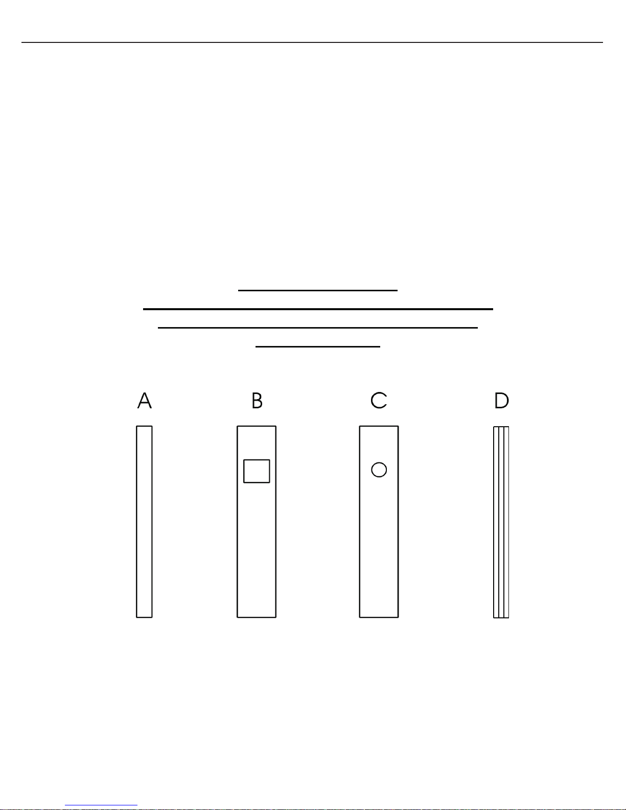
STEP 3: IDENTIFY SLAT WALL PARTS
Please note that we include ten extra slats just in case you have any parts that are
damaged in transit or at the job-site. We know how frustrating it can be to stop a job
due to a damaged part and we take every precaution to make sure that does not
happen.
*VERY IMPORTANT*
BE SURE TO IDENTIFY AND SEPARATE THE
DIFFERENT SLATS BEFORE BEGINNING
INSTALLATION.
The wall of your pool has four different types of slats. Please separate the four different types of slats before you
begin. The smooth surface of the slat ALWAYS faces in toward the water side of the pool. All ribs and bumps are
on the outside, or dry side of the pool. Shown below are the four different types of slats.
- A is a regular slat
- B is a skimmer slat
- C is a return slat
- D is a beam slat
Use your pool parts breakdown sheet to separate all pool components, becoming familiar with each part.

STEP 4 – UNPACKING THE POOL:
At this point you should open all of the cartons that have come with your pool. Separate all of the parts,
becoming familiar with each by checking them against the specific parts breakdown sheet packed in the yellow
envelope. Count the number of each part and check that against the packing list as well. This way if you are
missing something you can contact the people you purchased the pool from before you begin the construction
of the pool.
Below are some generic diagrams of oval pool components to help you identify the parts and where they will be
used. IMPORTANT: Do not attempt to assemble these parts now. Once you confirm that you have all of
the components needed for yourpool, continue on with the instructions.
TRADITIONAL BUTTRESS OVAL ASSEMBLY BUTTRESS-FREE OVAL ASSEMBLY:
Fig. 5
Fig. 6
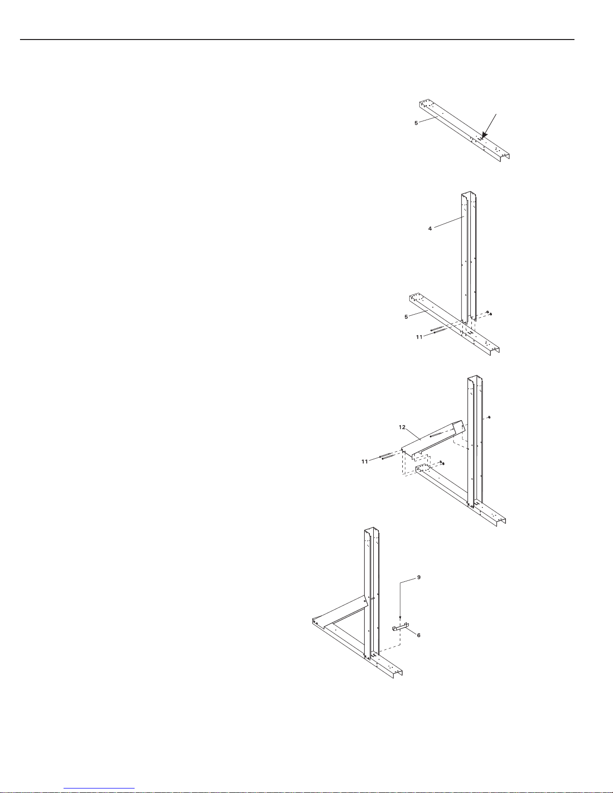
STEP 5 - PRE-ASSEMBLING THE STRAIGHT SIDES OF A TRADITIONAL BUTTRESS OVAL POOL ONLY:
*** THESE INSTRUCTIONS ARE FOR TRADITIONAL BUTTRESS OVAL POOLS ONLY! IF YOU HAVE A
BUTTRESS-FREE OVAL, PLEASE USE ALTERNATE STEP 5.
A) Start by laying the strap end channels out on the ground so
that the open ends face down. Notice the two slots on top of
each of these channels. You will not be using these slots in
the construction of the pool, but pay attention to where they
are located in the diagrams. They indicate which way the
channels are facing. See Fig.7
B) Now take the straight side 4"x4" Upright and push it down
over the strap end channel where those slots are located.
Position the open end of the straight side upright to face the
short end of the channel (the inside of the pool) as shown
in Fig.8. The two holes on each side of the upright should
line up with two of the holes on each side of the strap end
channel. Secure the parts with two 5/16" x 4 ½" bolts and
two 5/16" nuts. Repeat for all assemblies.
C) Once all of the straight side uprights are attached, you can
begin attaching the struts. This is done by pushing the
angled end of the strut (the end with two holes on each
side) over the end of the strap end channel and the other
side around the straight side upright. The hole on each side
of the strut lines up with the hole in the straight side
upright that is farthest from the open end of the straight
side upright. The two holes on the other end of the strut
line up with the only two holes in the back end of the strap
end channel. Secure the struts using three 5/16" x 4 ½"
bolts and three 5/16" nuts. See Fig.9 for visual instructions.
Slots
Fig. 7
Fig. 8
Fig. 9
PART IDENTIFIER
D) Now you can install the straight side bottom rail connectors.
Use one per strap end channel. Place the connector on top
of the strap end channel so that the open part of the
connector sits inside the straight side upright. The
hole connector will line upin the straight side
with the hole between the two slots on the strap
end channel. Secure the piece using a #12 x ¾" screw.
See Fig.10 for visual instructions.
Fig. 10
*Please do not be alarmed if you are not using all of the holes in the strap end channels. We use this same
channel for a few different products so there are some holes that you will not be using for this pool.
Please follow diagrams to be sure you are using all of the correct holes.
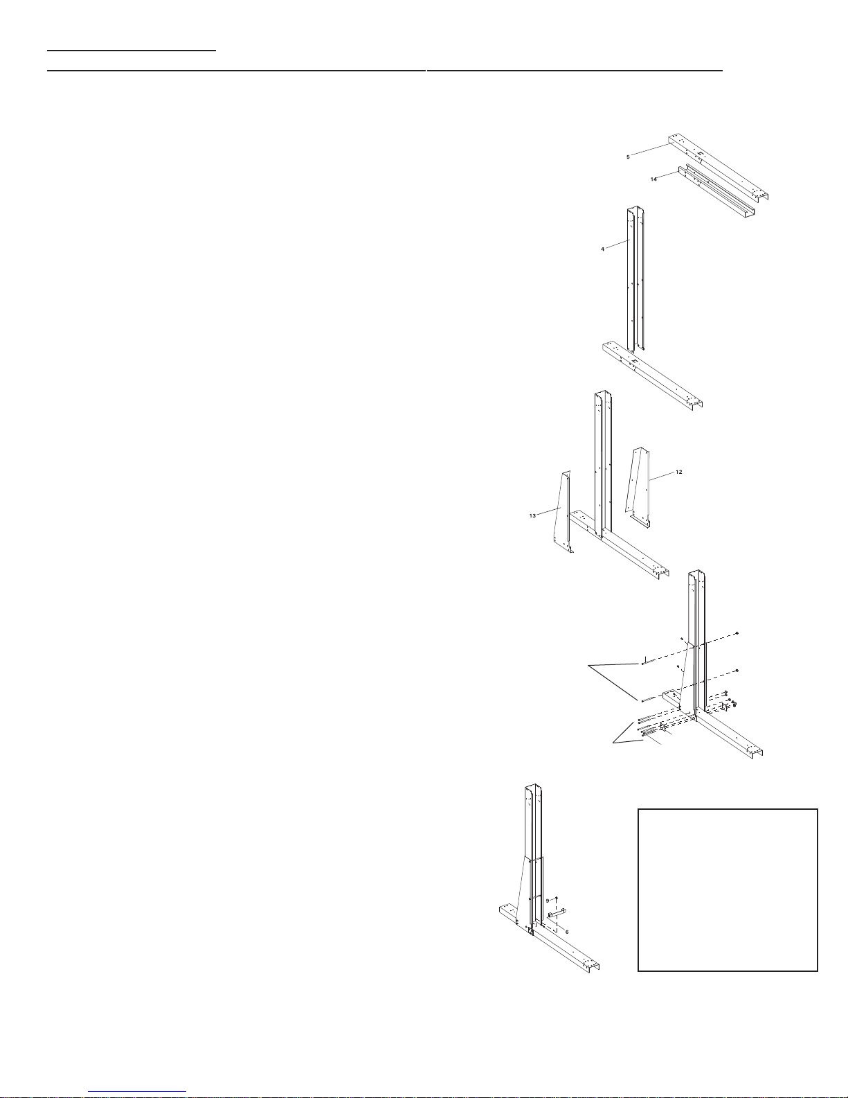
ALTERNATE STEP 5 PRE-ASSEMBLING THE STRAIGHT SIDES OF A BUTTRESS-FREE OVAL POOL ONLY:
*** IF YOU HAVE A TRADITIONAL BUTTRESS OVAL, PLEASE REFER TO THE PREVIOUS STEP 5.
A) Start by laying out the under box channels so that the open
sides of each under box channel is facing up. Then slide the
strap end channel over the top of the under box channels so
that they form a tube. Be sure that the holes in both channels
are aligned, but do not bolt them together yet. See Fig. 11
B) Now slide the straight side 4"x4" uprights over the strap
end channels making sure that the holes line up as
shown in Fig.12.
Fig. 12
Fig. 11
C) Once the straight side 4"x4" uprights are attached, apply the
left and right side gussets on each. The pieces are marked
"L" and "R". The gussets are applied under the channels and
around the straight side upright. Once you have them in
place screw the left and right gussets to each other using
three #10 screws. See Fig.13 for visual instructions.
D) All holes should be lined up at this point. Bolt the components
together as shown in the diagram. Use 5/16" x 5" long bolts
and 5/16" nuts for the channels, and 5/16" x 4 ½" long
stainless steel bolts for connecting the gussets to the uprights.
Remember to include the three-hole plate at the fronts of
the gussets. If these washers are left off your pool will break!
See Fig.14 for visual instructions.
E) Once all of the 5" long bolts have been tightened, install the
straight side bottom connectors. This is done by placing the
connector on top of the strap end channel just inside the
straight side upright. The hole in the connector should line
up with the hole in the strap end channel. Secure the
connector to the channel using a single # 12 x ¾" screw
for each as shown in Fig.15.
Fig. 15
4 1/2" long
ss bolts
5" long bolts
Fig. 13
16
15
11
PART IDENTIFIER
Fig. 14
*Please do not be alarmed if you are not using all of the holes in the strap end channels. We use this same
channel for a few different products so there are some holes that you will not be using for this pool. You will
also have 3 extra 5/16" x 4 1/2" stainless steel bolts per upright when installing the Butress-Free system.
Please follow diagrams to be sure you are using all of the correct holes and hardware.

STEP 6 - STRAP ASSEMBLY FOR TRADITIONAL BUTTRESS OVAL POOL ONLY:
*** USE THIS STEP FOR TRADITIONAL BUTTRESS OVAL INSTALLATION ONLY!
IF YOU HAVE A BUTTRESS-FREE OVAL, PLEASE SEE ALTERNATE STEP 6.
Notice that there are two different sizes of straps packed with your pool. Each strap is stamped with a part
number and a length.
A) If your pool is 12' wide, each strap will be made up of two 41.025" long pieces and one 39.275" long piece.
B) If your pool is 15' wide, each strap will be made up of four pieces. Three of the pieces will measure
40.683" long and one will measure 39.275" long.
C) If your pool is 18' wide, each strap will be made up of four pieces. Three of the pieces will measure
52.6875" long and one piece will measure 39.275" long.
St ra p S e cti on S iz e C h ar t :
12'x 17' 12'x 24' 15'x 26' 15'x30' 18'x 33' 18'x 40'
39.275”
40.683”
41.025”
52.6875”
2
4
3
6
3
9
4
12
4 6
12 18
Regardless of what size your pool is, each piece of every strap should be secured to the other
using two 5/16" x ½" bolts and two 5/16" nuts. All holes must be used.
Fig. 16
 Loading...