

Page 1
1
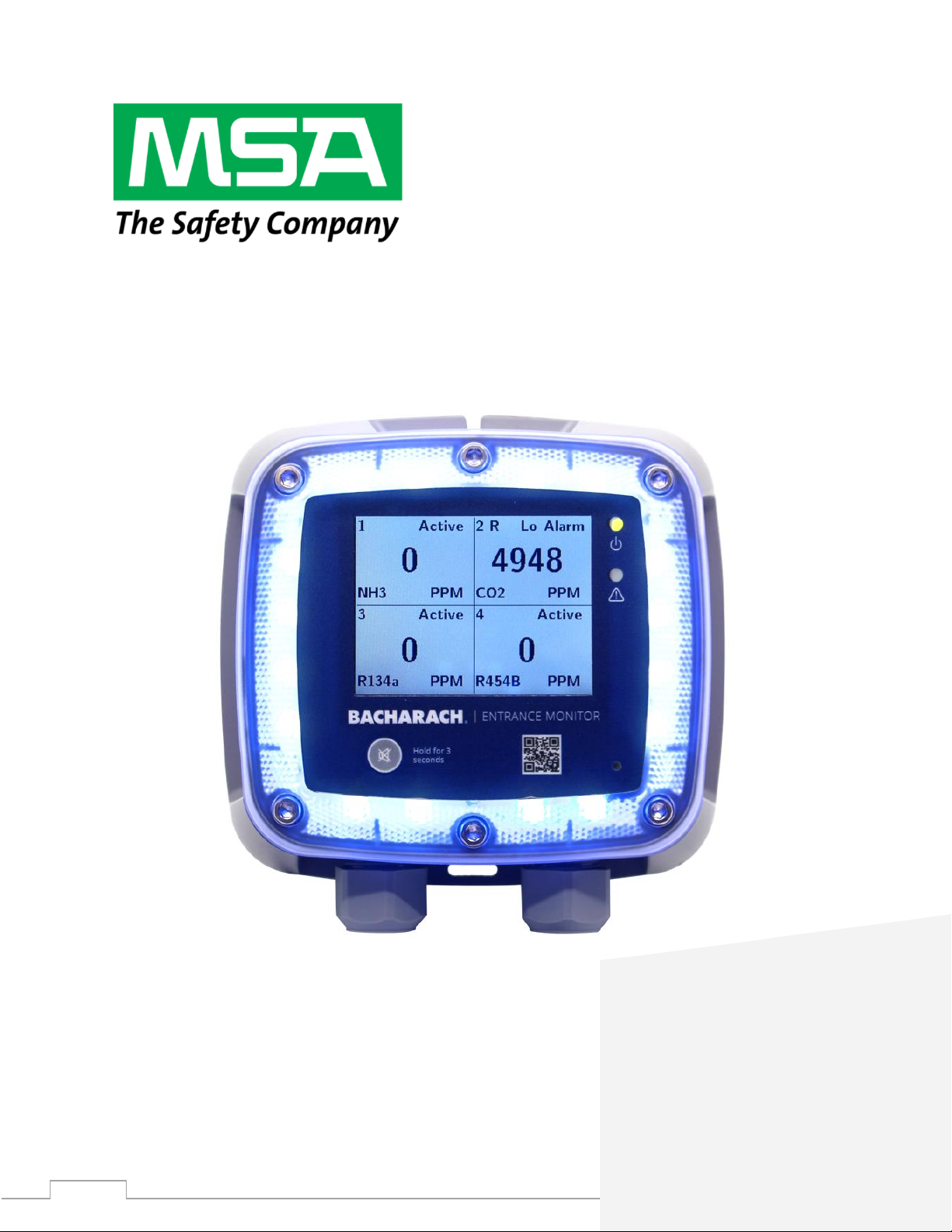
BACHARACH MGS-401 Entrance Monitor
for Commercial & Industrial Applications
Fixed Gas Detection
P/N: 1100-2527 | Revision 2.0
User
Manual
Page 2

BACHARACH MGS-401 User Manual
2
WARRANTY POLICY
MSA Bacharach, Inc. warrants to buyer that at the time of delivery this product will be free from defects in material
and manufacture and will conform substantially to MSA Bacharach, Inc.’s applicable specifications. MSA Bacharach’s
liability and buyer’s remedy under this warranty are limited to the repair or replacement, at MSA Bacharach’s option,
of this product or parts thereof returned to seller at the factory of manufacture and shown to MSA Bacharach, Inc.’s
reasonable satisfaction to have been defective; provided that written notice of the defect shall have been given by
buyer to MSA Bacharach, Inc. within one (1) year after the date of delivery of this product by MSA Bacharach, Inc.
MSA Bacharach, Inc. warrants to buyer that it will convey good title to this product. MSA Bacharach’s liability and buyer’s
remedy under this warranty of title are limited to the removal of any title defects or, at the election of MSA Bacharach,
to the replacement of this product or parts thereof that are defective in title.
THE FOREGOING WARRANTIES ARE EXCLUSIVE AND ARE GIVEN AND ACCEPTED IN LIEU OF (I) ANY AND ALL OTHER
WARRANTIES, EXPRESS OR IMPLIED, INCLUDING WITHOUT LIMITATION THE IMPLIED WARRANTIES OF
MERCHANTABILITY AND FITNESS FOR A PARTICULAR PURPOSE: AND (II) ANY OBLIGATION, LIABILITY, RIGHT, CLAIM
OR REMEDY IN CONTRACT OR TORT, WHETHER OR NOT ARISING FROM MS A BACHARACH’S NEGLIGENCE, ACTUAL
OR
IMPLIED. The remedies of the buyer shall be limited to those provided herein to the exclusion of any and all other
remedies including, without limitation incidental or consequential damages. No agreement varying or extending the
foregoing warranties, remedies or this limitation will be binding upon MSA Bacharach, Inc. unless in writing, signed
by a duly authorized officer of MSA Bacharach.
Register Your Warranty by Visiting: www.mybacharach.com
SERVICE POLICY
MSA Bacharach, Inc. maintains a service facility at the factory. Some MSA Bacharach distributors / agents may also
have repair facilities; however, MSA Bacharach assumes no liability for service performed by anyone other than MSA
Bacharach personnel. Repairs are warranted for 90-days after date of shipment (sensors, pumps, filters and batteries
have individual warranties). Should your instrument require non-warranty repair, you may contact the distributor
from whom it was purchased, or you may contact MSA Bacharach directly.
If MSA Bacharach is to do the repair work, send the instrument, prepaid, to the closest service center. Prior to shipping
equipment to MSA Bacharach, visit www.mybacharach.com for a Returned Merchandise Authorization Number ( #).
All returned goods must be accompanied by a RMA #. Pack the equipment securely (in its original packing, if possible),
as MSA Bacharach cannot be held responsible for any damage incurred during shipping to our facility. Always include
your RMA #, shipping address, telephone number, contact name, billing information and a description of the defect
as you perceive it. You will be contacted with a cost estimate for expected repairs prior to the performance of any
service work. For liability reasons, MSA Bacharach has a policy of performing all needed repairs to restore the monitor
to full operating condition.
NOTICES
Product improvements and enhancements are on-going, therefore the specifications and information contained in
this document may change without notice.
MSA Bacharach, Inc. shall not be liable for errors contained herein or for incidental or consequential damages in
connection with the furnishing, performance, or use of this material.
No part of this document may be photocopied, reproduced, or translated to another language without the prior
written consent of MSA Bacharach, Inc.
Copyright © 2021, MSA Bacharach, Inc., All Rights Reserved.
BACHARACH is a registered trademark of Bacharach, Inc. All other trademarks, trade names, service marks and logos referenced herein belong to
their respective companies.
Page 3
BACHARACH MGS-401 User Manual
3
1. Introduction
1.1 About this Manual
Thank you for investing in a MSA Bacharach MGS-401 Entrance Monitor. To ensure operator safety and
the proper use of the controller, please read the contents of this manual for important information on the
operation and maintenance of the instrument.
1.2 Conventions
1.2.1 Iconography
Alert
Icon
Description
WARNING
Potentially hazardous situation which, if not avoided, could result in death or
serious injury.
CAUTION
Potentially hazardous situation which, if not avoided, could result in minor or
moderate physical injury.
IMPORTANT
Additional information on how to use the product.
Page 4
BACHARACH MGS-401 User Manual
4
1.3 General Safety Statements
WARNING: Read this manual carefully before using the device. The device will perform as designed
only if it is used and maintained in accordance with the manufacturer's instructions. Otherwise, it
could fail to perform as designed.
WARNING: Make sure any personnel who will be installing, using, or maintaining this device have
access to the user manual. If electronic access to the user manual is not possible, print a copy of the
manual and keep it in an accessible location near the device.
Failure to obey the following guidelines and/or incorrect installation, operation, servicing, or
maintenance of the device can cause incorrect operation of the device, and personnel who rely on
this product for their safety can sustain serious personal injury or death.
WARNING: Install, operate, and maintain the device in strict accordance with its labels, cautions,
warnings, instructions, and stated limitations.
The device contains no replaceable or serviceable parts. Repair or alteration of the system beyond
the scope of these instructions or by anyone other than authorized personnel can cause incorrect
operation of the device.
The device is intended for indoor use only. Do not use the device for outdoor applications.
Make sure the device is not located in areas that contain a flammable mixture of gas and air.
Otherwise, an explosion can occur.
The device is not intrinsically safe. Do not use the device in areas classified as hazardous or locations
where explosive concentrations of combustible gases or vapors can occur.
DO NOT continue to use this equipment if there are any symptoms of damage or improper function.
In the case of such an occurrence, de-energize the power supply and contact a qualified repair
technician or the nearest MSA Bacharach Service Center.
Failure to follow these warnings can result in serious bodily injury or death.
2. Product Description
2.1 Product Overview
The MGS-401 Entrance Monitor is used to display the gas concentration in compressor rooms to
ensure concentrations are known before workers enter the space.
The MGS-401 can display up to (4) different diffusion gas detectors on a single 3.5” LCD screen and
communication is done through a digital Modbus network. In addition, the MGS-401 can be used on
larger compressor room networks with multiple doors. The IP54 enclosure ensures environmental
protection for indoor or outdoor applications at temperatures of -20oC – 50oC.
The MGS-401 is powered by 24VAC/DC and includes a 10A, 24VAC/DC relay to connect to ventilation,
a silence pushbutton, and a forced alarm input. The instrument also includes a perimeter strobe and
+85dB audible alarm for notification of personnel.
Page 5
BACHARACH MGS-401 User Manual
5
Warning: This instrument indicates gas concentration(s) that may be present in the space
where the attached gas detectors are located. The primary instrument to alarm personnel of
a low alarm or high alarm concentration level are the gas detectors that are monitoring the
space. If the attached gas detectors indicate a low alarm or high alarm concentration level,
DO NOT enter the monitored space.
Failure to follow this warning can result in serious bodily injury or death.
Warning: If gas concentrations are increasing rapidly or are approaching OEL (Occupational
Exposure Levels) or STEL (Short Term Exposure Limit) levels, evacuate the space and take
measures to reduce gas concentrations to acceptable levels before re-entering.
Failure to follow this warning can result in serious bodily injury or death.
2.2 System Guidance
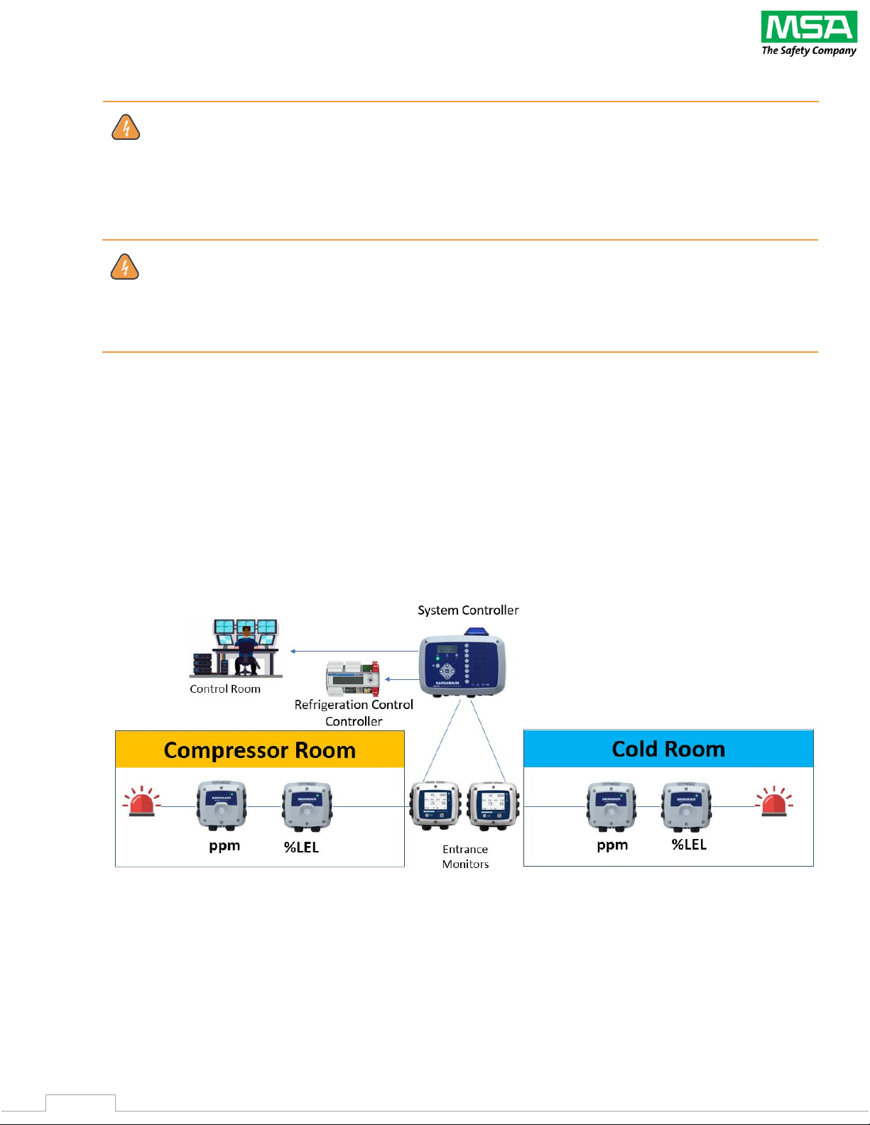
The MGS-401 Entrance Monitor is but one piece of a complete gas detection system. MGS-400 Series
Gas detectors in the monitored area can signal via digital bus, relays and/or audible and visual
output. The digital Modbus connection from the gas detectors provides the responses to the MGS401, which in turn provides an audible and visual alarm outside the monitored space. In addition, the
MGS-401 displays any gas concentration level in the space for additional information and visual
monitoring. System configuration will determine whether the alarms signals are addressed in the
monitored space or at a controller or BMS/BAS level. Consultation with local inspection authorities is
recommended.
For recommended alarm levels refer to NIOSH (National Institute of Occupational Safety and Health)
and OSHA (Occupational Safety and Health Administration) standards for OEL (Occupational
Exposure Limit) and STEL (Short-Term Exposure Limit) gas exposure levels for best practice. In
addition, ASHRAE 15/34, IIAR 2, EN378 and CSA-B52 provide recommended alarm levels for certain
types of gases.
Page 6
BACHARACH MGS-401 User Manual
6
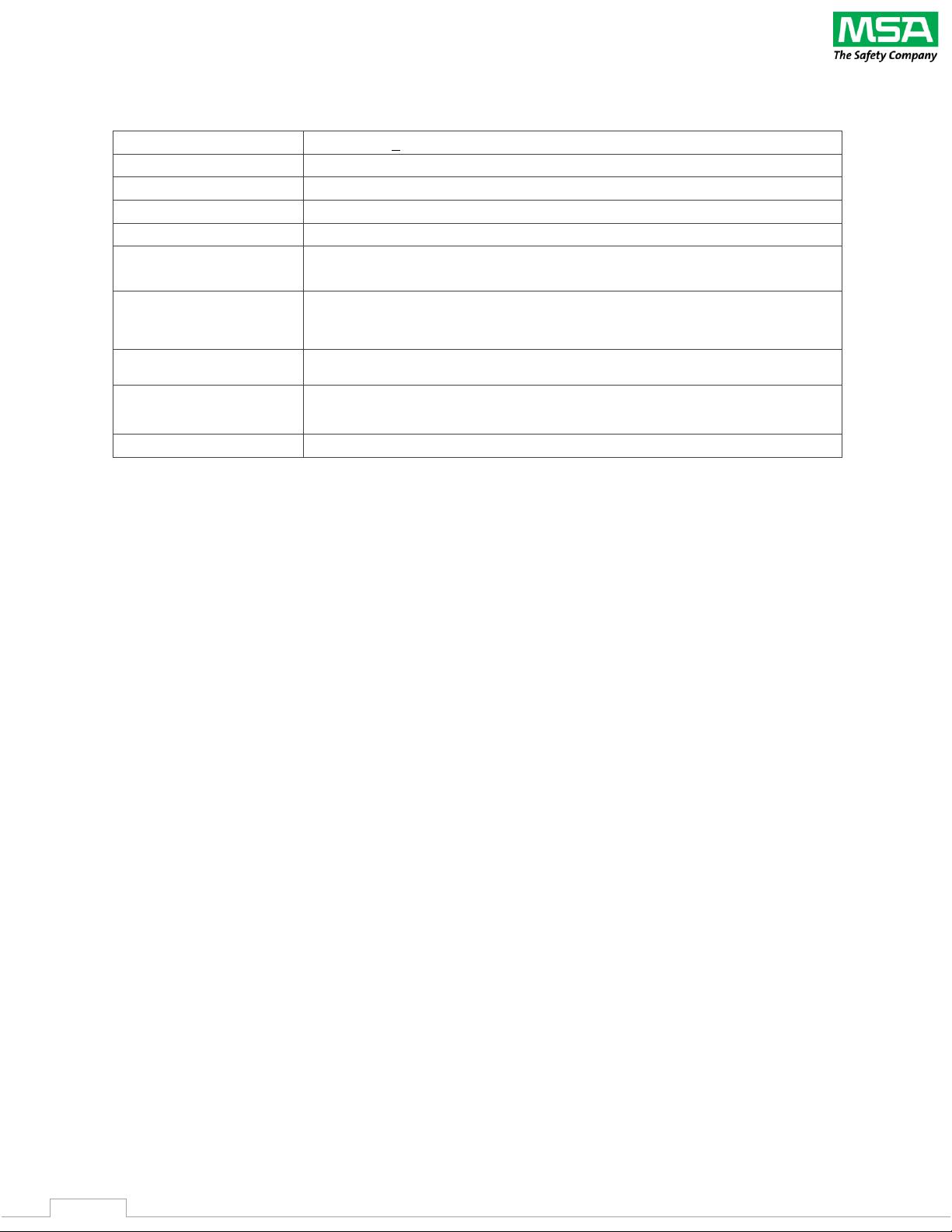
2.3 Design Features
Input Power
24VAC/DC, +20%, 7W max.
Enclosure Rating
IP54
Operating Temperature
-20oC to 50oC
Relative Humidity
0 to 95% non-condensing
Altitude
6560 ft (2000 M)
Communications
RS485 Modbus RTU Client for Gas Detectors
RS485 Modbus RTU Server for BMS
Visual / Audible Signals
Integrated high output visual strobe
Integrated high output audible alarm
Output
(1) Relay, 10A @ 24VAC/DC
Inputs
Remote silence
Forced alarm
Agency Approvals1
CE, EN 50270:2015, UL/CSA/EN 61010-1
1 - MET Labs has not evaluated the efficacy of this device.
Page 7
BACHARACH MGS-401 User Manual
7
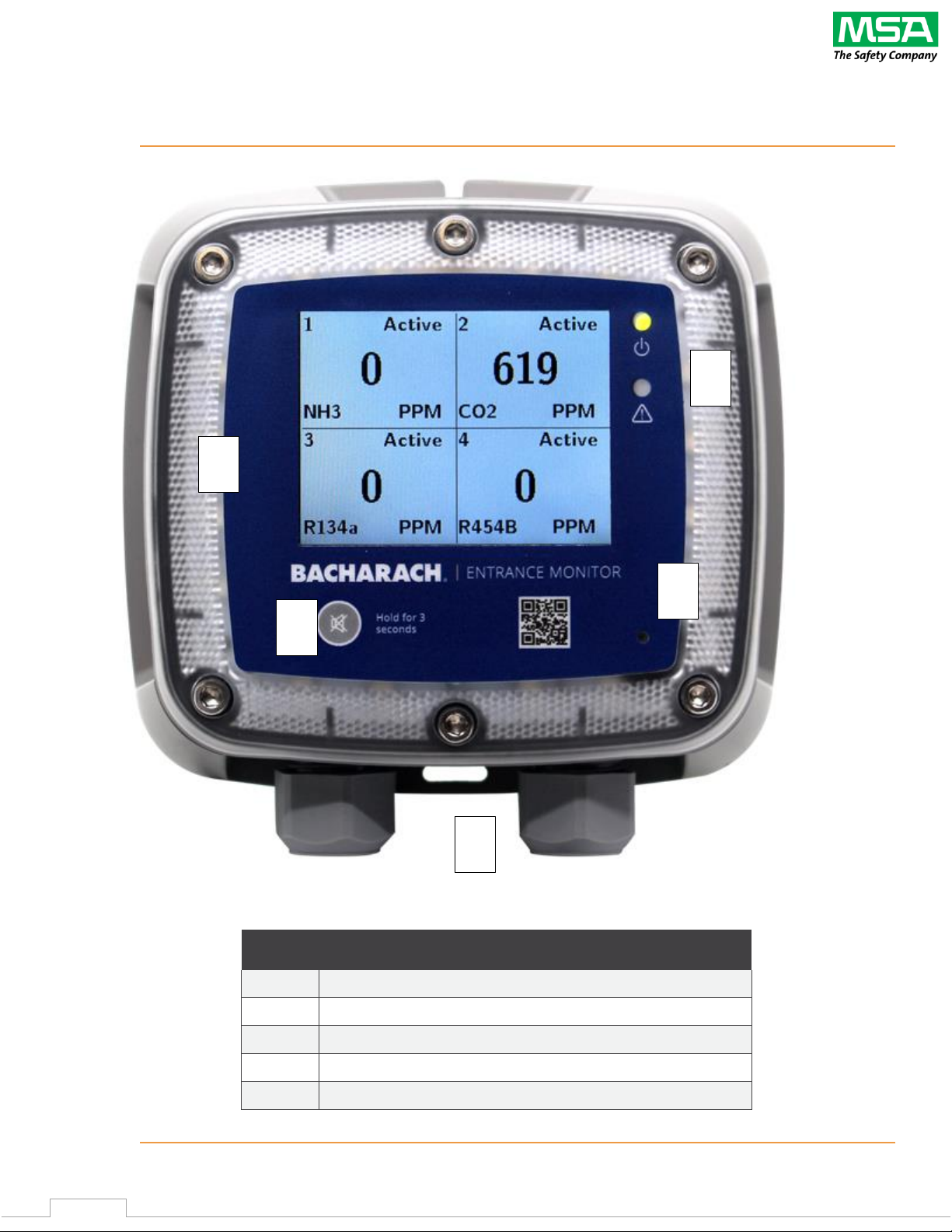
2.4 Front Panel
Figure 2-4 - Front Panel Layout
# Front Panel Description
1
Integrated visual alarm in bezel
2
Controller Power & Fault LEDS
3
Mute alarm button
4
>80dB Alarm
5
½ “ NPT Cable Glands (x2)
4
3 2 1
5
Page 8
BACHARACH MGS-401 User Manual
8
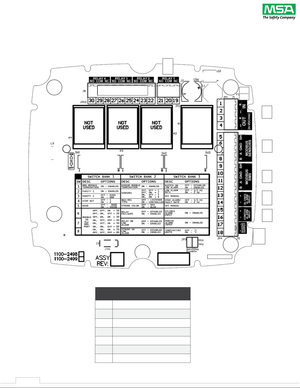
2.5 Back of Lid Components
Figure 2-5 - MGS-401 Under Lid Connections and Configuration
#
Component Description
1
24VAC/DC Input/Output
2
Modbus to Gas Detectors
3
Modbus to BMS
4
Remote Silence Alarm Input
5
Forced Alarm Input
6
Aux. Buzzer Output
7
Alarm Relay
6
1
5
4
3
2
7
Not populated
Page 9
BACHARACH MGS-401 User Manual
9
3. Installation
3.1 Warnings & Cautions
WARNING: Make sure the device is installed in a clean, dry area that is protected from
vibration, including but not limited to a chiller, and heat sources.
Do not paint the device. Paint deposits can prevent correct operation of the device.
To prevent electrostatic discharge (ESD), connect an ESD wrist strap to the ESD connection
point inside the device enclosure before doing work inside the enclosure. ESD can cause
damage to the device.
Do not touch the electronic circuit boards.
Do not install or operate a device that has damage.
Disconnect all power sources before opening the device enclosure. Failure to do so can
result in electrical shock. Electrical shock can cause damage to the device and injury to
personnel.
Never operate the device without a protective ground. Operating the device without a
protective ground can result in electrical shock. Electrical shock can cause damage to the
device and injury to personnel.
Locate the device next to the entry door of the area where the MGS-family gas detection
instrument(s) is installed and where it is easily visible to personnel entering the area where
the MGS-family gas detection instrument(s) is installed.
Failure to follow these warnings can result in serious bodily injury or death.
3.2 Preliminary Inspection
The MGS-401 Entrance Monitor has been thoroughly inspected and tested prior to shipment from the
factory. Nevertheless, it is recommended that the instrument be re-checked prior to installation.
Inspect the outside of the enclosure to make sure there are no obvious signs of shipping damage.
Remove the top of the enclosure. Visually inspect the interior of the enclosure for loose components
that may have become dislodged during shipment. If damage is discovered, please contact a qualified
repair technician or the nearest MSA Bacharach Service Center for assistance.
3.3 Suitable / Appropriate Locations
The MGS-401 Entrance Monitor is design for use in mechanical rooms, warehouses, cold storage, or
freezers to help comply with international safety standards
(EN 378, ASHRAE 15, CSA-B52)
. The MGS-
401 is a IP54
(poly carbonate)
rated enclosure and can be placed in environments from -20 OC to +50 OC
ambient temperatures. Typical installations would be either inside or outside the door of an enclosed
space to have local audible and visual alarms as required by safety standards.
Page 10
BACHARACH MGS-401 User Manual
10
3.4 Mounting the Gas Detection Controller
1. Mount the MGS-401 according to the product dimensions, maximum wiring
lengths and following considerations:
• Environment: the full range of environmental conditions when selecting a location.
• Accessibility: the degree of accessibility required for maintenance purposes
when selecting a location.
2. Using a 5/32″
(4 mm)
hex key / Allen wrench
(not included),
remove the lid
3. Set the lid and rubber gasket aside to be reinstalled later.
4. Use the provided mounting screws to mount the enclosure base to the mounting surface.
3.5 Power Wiring
3.5.1 Connecting the 24VAC/DC Power
The MGS-401 Entrance Monitor features (2) ½” NPT cable fittings or 15mm cable glands that can be used for
power entry wiring
(item 5 in “Figure 2-4 - MGS-401 Front Panel).
Alternately, ½ conduit could be used but the
connection must be gasketed to ensure IP54 rating.
WARNING: Install a circuit breaker for the incoming power connections of the device. Put
the circuit breaker in a location that is easy to access and near the device. Clearly mark the
circuit breaker as the disconnecting unit for the device.
Ensure that grounding of the device is connected prior to starting the device.
A qualified electrician must do electrical wiring.
Wiring must comply with all applicable local electrical safety codes.
Make sure that the copper conductors used to supply mains meet all local electrical safety
codes.
Failure to follow these warnings can result in serious bodily injury or death.
Locate the 24VAC/DC power input terminal block
(Item 1, “Figure 2-5 - MGS-401Connections and
Configuration)
and remove it from the controller.
1. Ensuring that the main power is turned off at the upstream circuit breaker or disconnect
switch, feed the incoming power leads through one of the ½ openings and into the appropriate
terminals
(+ (Positive); – (Negative))
on the terminal block.
2. Do not reengage upstream circuit breaker or disconnect until all the connections in section
3.6 Other Electrical Connections have been addressed.
Page 11

BACHARACH MGS-401 User Manual
11
3.6 Other Electrical Connections
The remaining electrical connections that are available are the alarm relay, Modbus to the BMS and Gas
detectors, remote alarm silence and forced alarm inputs and also a remote buzzer output. The alarm relay is
a standalone (3) wire terminal block, and the other connections are a common (14) wire terminal block (see
Figure 2-5 – MGS-401 Under Lid Connections and Configuration). The connections can be made through one or
two of the ½” NPT cable fittings or 15mm cable glands. In addition, the MGS Series Cable Sizing and Selection
Guide, Rev. 0, March 2021, which can be found on www.mybacharach.com, can be used to assisting in cable
sizing and layout.
3.6.1 For convenience there are two Modbus terminal block connections, Modbus BMS for connection to a
higher level BMS controller and a Modbus Sensors for connection to the monitors sensor(s). Follow
standard Modbus practices for these connections. The Modbus configuration to the BMS and the Sensors
or gas detectors must be completed. See section 4.1, MGS-401 Configuration for Modbus settings.
3.6.2 The alarm relay is rated 10A, 24V AC/DC and will respond to either high alarms (factory default) or, in
addition, low alarms. In addition, the relay will change state and alarm if there are any faults detected
with the MGS-401 Entrance Monitor or with any of the connected gas detectors. The relay can also be
configured for failsafe response. See section 4.2, MGS-401 Configuration for relay settings.
3.6.3 The Remote silence alarm input is a terminal block where a momentary pushbutton/remote silence input
would typically be connected is a normally open connection. The pushbutton, in a remote location, is
used for personnel to silence the audible alarm momentarily with visual alarms still activated. The
audible alarm will reengage if the alarm condition hasn’t been cleared in 30 minutes. See section 4.2,
MGS-401 Configuration for Remote Silence settings.
3.6.4 The Forced alarm input is terminal block where a momentary pushbutton/forced alarm input would
typically be connected is a normally open pushbutton. The pushbutton, in a remote location, is used for
personnel to force an alarm on the system to alert others of a potentially unsafe situation. The forced
alarm will cause the gas detection system to engage both audible and visual alarm. See section 4.2, MGS401 Configuration for Forced alarm settings.
3.6.5 The Buzzer output is a parallel connection to the on-board >80dB audible alarm. This terminal block is
used if an additional buzzer is needed for a remote location. The remote buzzer will activate and be
silenced as the on-board buzzer is configured.
Page 12
BACHARACH MGS-401 User Manual
12
4. MGS-401 Configuration
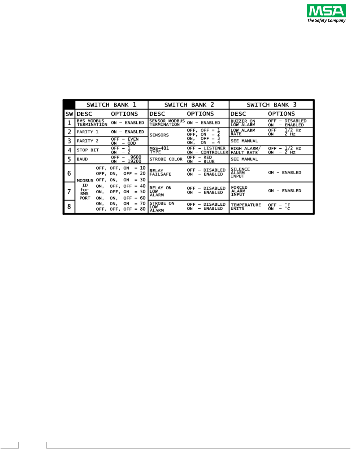
The configuration of the MGS-401 is done with (3) banks of DIP switches on the back of the MGS-401 lid.
Through these switches the user can configure the Modbus settings, MGS-401 Entrance Monitor as well as
many features of the perimeter strobe, on-board audible sounder as well as input and output configurations.
Follow the directions below to configure your instrument.
Figure 4 MGS-401 DIP Switch configuration.
4.1 BMS Modbus Configuration
4.1.1 The MGS-401 Entrance Monitor can be used as a standalone device to monitor up to (4) MGS gas sensors
or it can be used as part of a higher-level Building Automation System. Switch bank 1, positions 1 through
8 (see figure 2.5,
MGS-401 Under Lid Connections and Configuration
) are used to configure the BMS
Modbus Server settings when use with higher level controls. Please refer to Modbus best practice when
making these choices. It is important ALL of the following instrument settings corresponded to the BMS
settings for proper operation.
1. Bank 1, Switch 1 is used to enable the BMS Modbus terminating resistor. The default is ‘disabled’
or OFF.
2. Bank 1, Switch 2 is used to enable the parity of the Modbus network. The default is ‘disabled’, ‘no
parity’ or OFF.
3. Bank 1, Switch 3 is used to set the parity of the Modbus network to either ‘even’ – OFF switch
position or ‘odd’ – ON switch position. The default is ‘even’ parity or OFF.
4. Bank 1, Switch 4 is used to set the Stop Bit of the Modbus network to either ‘1’ or ‘2’. The default
is STOP BIT ‘1’ or OFF.
5. Bank 1 Switch 5 is used to set the Baud Rate of the Modbus network to either ‘9600’ or ‘19200’.
The default Baud Rate is ‘9600’ or OFF.
Page 13

BACHARACH MGS-401 User Manual
13
6. Bank 1, Switches 6, 7 and 8 are used to assign a Modbus ID to the MGS-401 when used on a BMS
network. The Modbus ID is a combination of all three switch positions. The default setting for the
Modbus ID is ‘80’ or OFF, OFF, OFF.
4.2 MGS-401 Configuration
4.2.1 The MGS-401 can be configured as a ‘Controller’ or as a ‘Listener’. If there are no other Modbus
‘controllers’ on the network, the MGS-401 must be configured as a ‘Controller’, see configuration advice
below. As a ‘Controller’ the MGS-401 will actively seek changes to the network data in the connected gas
detectors. If there is a Modbus controller on the network (MGS-408, MGS-402 or another Modbus
controller) other than the MGS-401, the MGS-401 must be configured as a ‘Listener’. When configured as
a ‘Listener’ the MGS-401 not seek network data on the Modbus network but will respond to the activity
between the controller that is seeking the network data from the connected gas detectors. You can have
more than (1) MGS-401 Entrance Monitor on the network at one time – multiple entrances to a monitored
space. If an MGS-401 is configured as a ‘Controller’ all other Entrance Monitors must be configured as
‘Listeners’. The MGS-401 Entrance Monitor can monitor up to (4) different Modbus IDs on the network.
IMPORTANT - When configured the Entrance Monitor is expecting the sensors to be Modbus address 01,
02, 03 and 04 depending on how many are configured. Other configuration features include perimeter
strobe options, relay configuration, and enabling auxiliary inputs. These will be explained in this section.
1. Bank 2, Switch 1 is used to enable the Sensor Modbus Termination. Please refer to Modbus best
practice when making these choice. The default is ‘Not Enabled’ or OFF
2. Bank 2, Switches 2 and 3 are used to configure the number of sensors the MGS-401 is expecting
to be connected to, up to a maximum of 4. The default is one sensor or OFF, OFF
3. Bank 2, Switch 4 is used to configure the MGS-401 for ‘Controller’ mode or ‘Listener’ mode as
described above. The default is ‘Listener’ or OFF.
4. Bank 2, Switch 5 is used to configure the color of the perimeter strobe to either ‘Blue’ or ‘Red’. The
default is ‘Red’ or OFF.
5. Bank 2, Switch 6 is used to configure the Alarm Relay to be ‘Failsafe’. In failsafe mode the relay will
change state when power is turned on and will change state again if power is lost or if there is an
alarm or fault condition. The default is ‘NOT Failsafe’ or OFF.
6. Bank 2, Switch 7 is used to ‘Enable’ the Alarm Relay to change state on a LOW ALARM condition.
The default is ‘NOT Enabled’. NOTE – The MGS-401 will always alarm during a HIGH ALARM
condition or a FAULT condition, this is not configurable and is required by safety standards.
7. Bank 2, Switch 8 is used to ‘Enable’ the Perimeter Strobe during a LOW ALARM condition. The
factory default is ‘DISABLED’ or OFF.
8. Bank 3, Switch 1 is used to ‘Enable’ the >80dB buzzer during a LOW ALARM condition. The factory
default is ‘DISABLED’ or OFF.
9. Bank 3, Switch 2 is used to configure the LOW ALARM Buzzer and Strobe rate to either ’½ Hz’ or ‘2
Hz’. The factory default is ‘½ Hz’ or OFF.
10. Bank 3, Switch 3 is unused. The factory default is ‘DISABLED’ or OFF.
11. Bank 3, Switch 4 is used to configure the HIGH ALARM Buzzer and Strobe rate to either ’½ Hz’ or ‘2
Hz’. The factory default is ‘½ Hz’ or OFF.
12. Bank 3, Switch 5 is unused. The factory default is ‘DISABLED’ or OFF.
Page 14

BACHARACH MGS-401 User Manual
14
13. Bank 3, Switch 6 is used to ENABLE the Silence Alarm input. The factory default is ‘DISABLED’ or
OFF.
14. Bank 3, Switch 7 is used to ENABLE the Forced Alarm Input. The factory default is ‘DISABLED’ or
OFF.
15. Bank 3, Switch 8 is used to set the temperature units on the MGS-401 Entrance Monitor to either
oF or o
C. The factory default is ‘DISABLED’ or oF.
4.3 MGS-401 Final Installation Check
4.3.1 As a final check, ensure that all wiring and terminal blocks are secured. Ensure that none of the wires in
any of the terminations have any strands of wire that could be potential short circuits. Carefully remove
any of the slack from cable(s) through the ½” NPT cable fittings or 15mm cable glands.
Replace the rubber gasket and lid onto the instrument base. Using a 5/32″ (4 mm) hex key / Allen wrench
(not included), secure the lid by tightening the (6) Hex Head screws in and ‘X’ pattern from top left to lower
right, upper right to lower left and then the remaining center top and bottom screws. Torque all screws
to 15 to 20 lbf in (1.5 to 2.0 Nm.).
Page 15
BACHARACH MGS-401 User Manual
15
5. Power Up
Once the MGS-401 Entrance Monitor has properly wired and configured and the lid is installed, the power can
be turned on at the circuit break or disconnect.
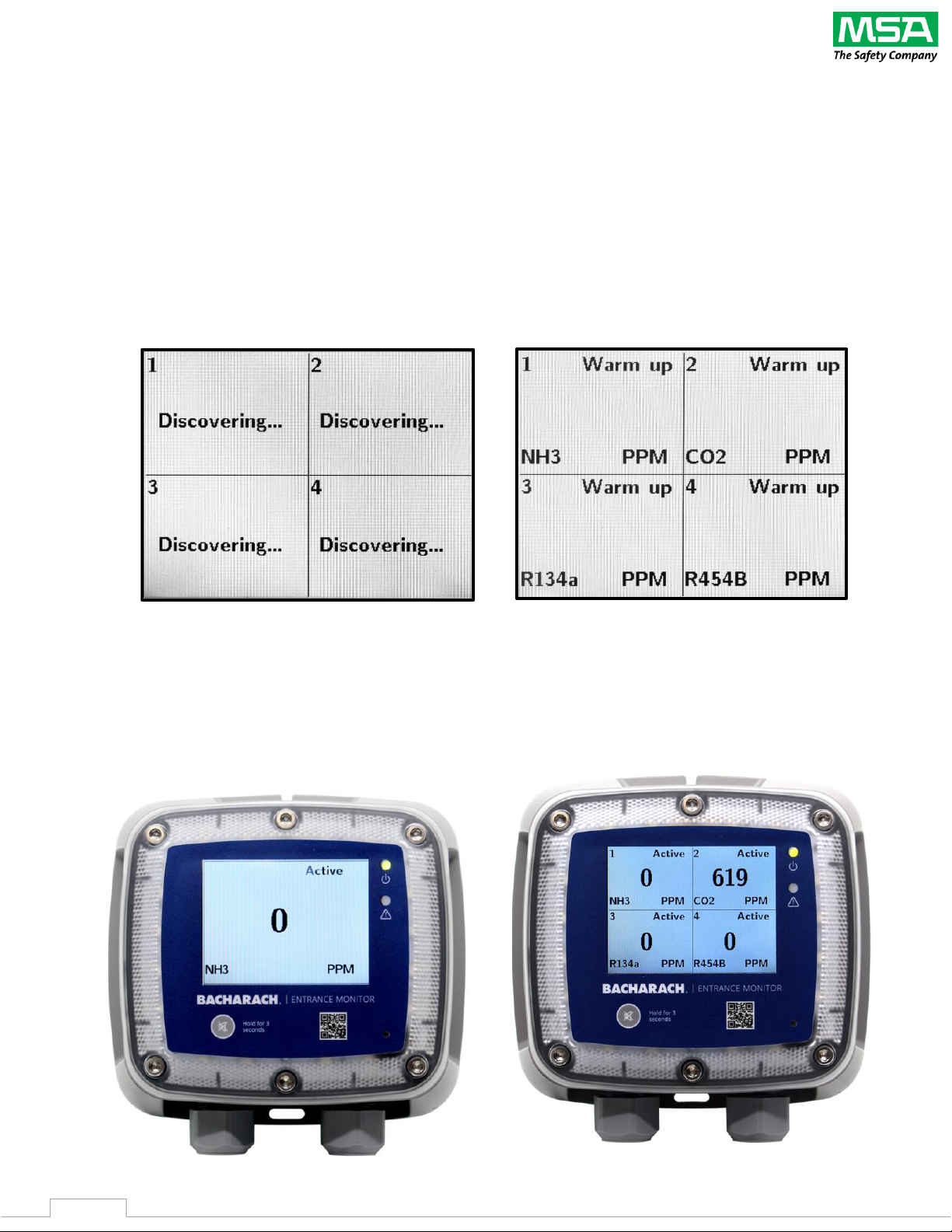
1. Once powered up the MGS-401 will attempt to ‘discover’ all the MGS Gas Detectors that it is
configured to monitor, up to (4). Once discovered on the network each gas detector will show
‘Warm Up’ in the upper right of the gas detector quadrant. This will change to ‘Active’ once the gas
detectors have completed their warmup procedure. Some gas detectors may take up to a few
minutes to complete the warm-up cycle.
2. If one gas detector is configured to the MGS-401 the entire LCD screen will be populated as shown
below. If 2-4 gas detectors are configured to the MGS-401 the LCD screen will be populated in
quadrants. If only 2-3 gas detectors are configured, then the remaining quadrants will show
‘Inactive’.
Page 16
BACHARACH MGS-401 User Manual
16
5.2 Operation
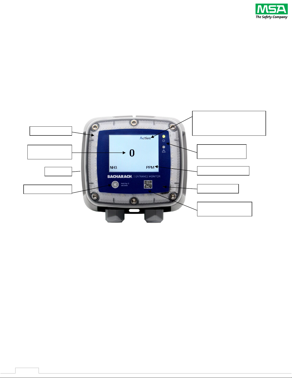
5.2.1 During normal operation the MGS-401 will monitor the connected gas detector(s) and display the
monitored location gas concentration as provided by the gas detectors in the location. If the gas
detectors in the monitored area respond to any preset alarm level or a fault occurs on the system the
MGS-401 Entrance Monitor will display that information on the LCD and respond with audible and visual
alarms, configured relay response and other countermeasures that are connected or configured. The
following graphic shows details of a single configured gas detector.
• PPM, PPB, %LEL, %Vol
• Gas Type
• Internal Sounder
• Active – Sensor is active
• Inactive – Sensor is not configured
• R – Relay is operating – alarm or
fault
• QR Code – This MGS-401
User Manual
• Perimeter Strobe
• Silence Pushbutton
• Power
• System Fault
• Gas concentration
@ Gas Detector
Page 17
BACHARACH MGS-401 User Manual
17
6. Trouble shooting
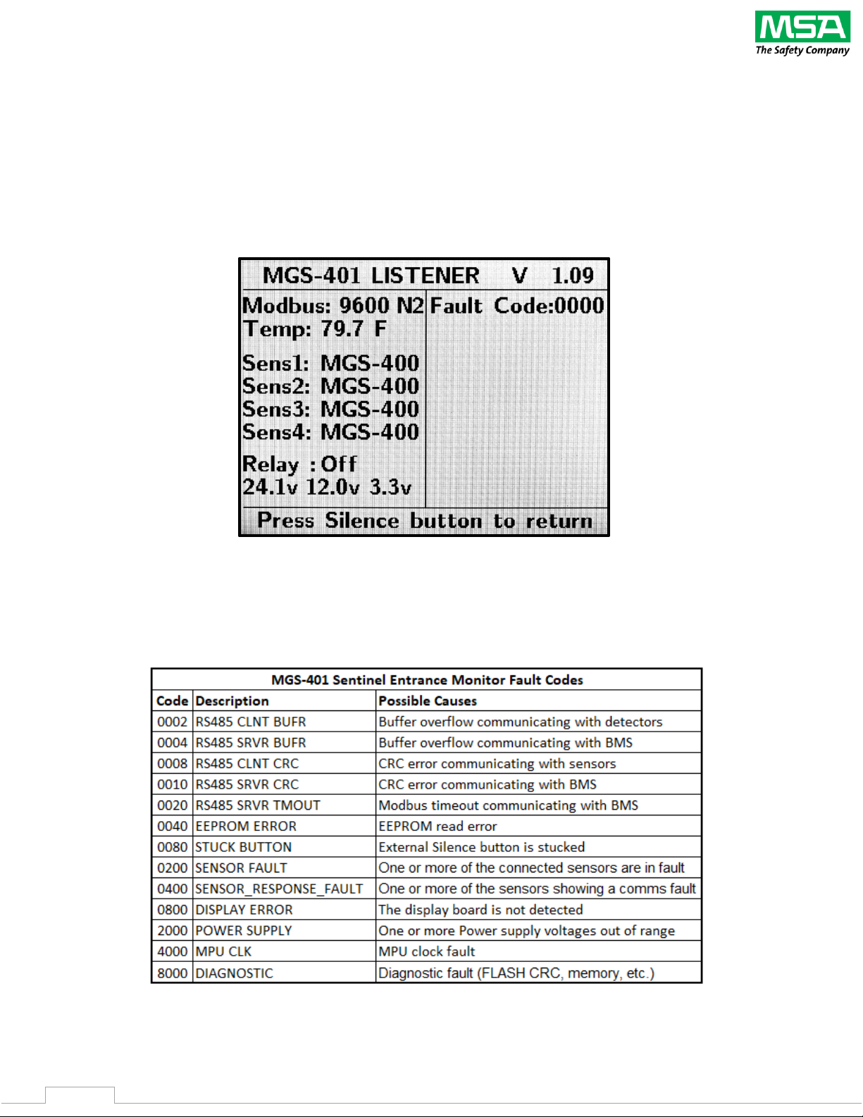
6.1.1 The System screen can be accessed by pressing the Silence button on the MGS-401 front panel (3)
consecutive times within 3 seconds. The System screen will show some of the configuration of the
MGS401. In addition, it will display any MGS-401 Fault Codes that may be present. See Section 6.1.2 Fault
Codes for Fault Code details.
6.1.2 Fault codes
Page 18
BACHARACH MGS-401 User Manual
18
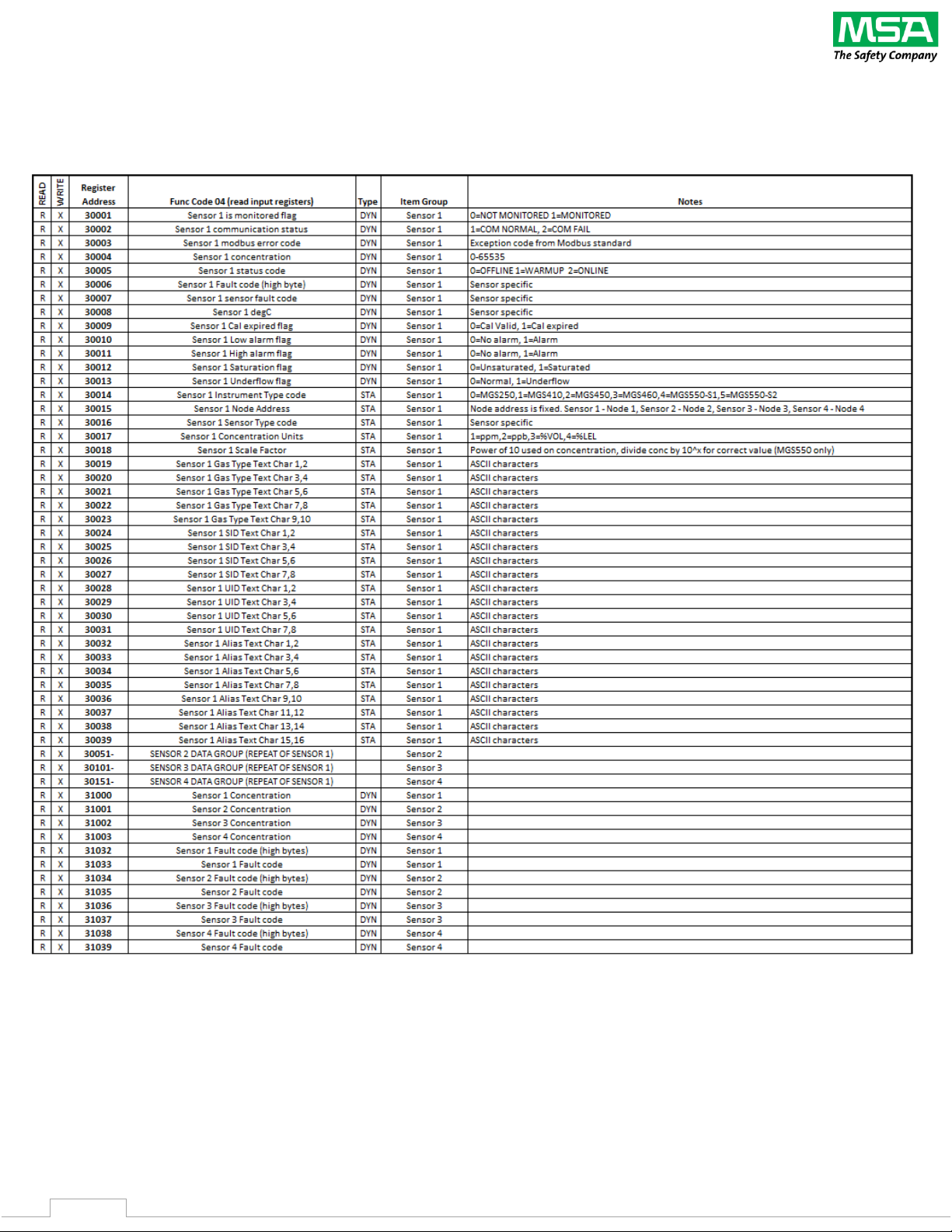
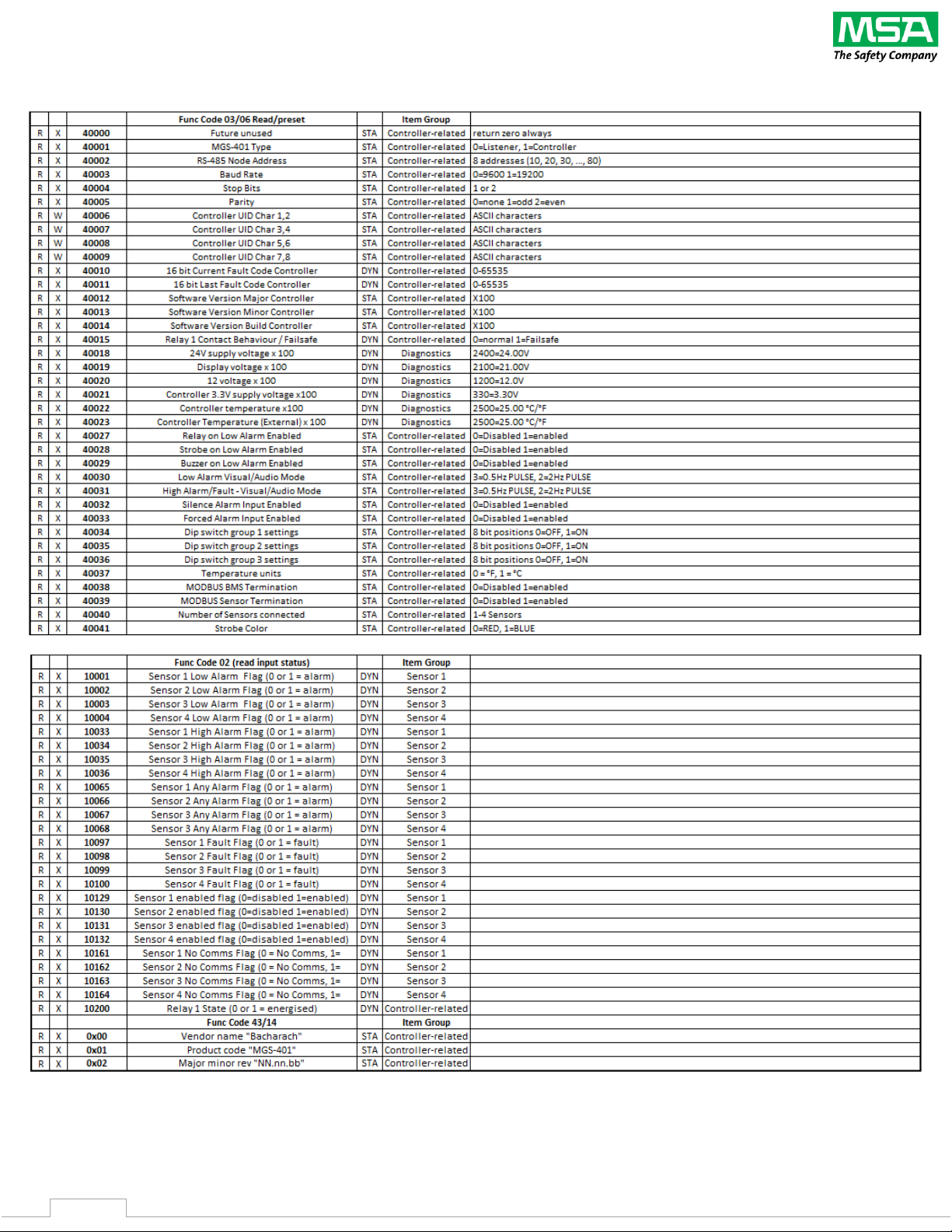
7. Modbus Map
Page 19
BACHARACH MGS-401 User Manual
19
Page 20
BACHARACH MGS-401 User Manual
20
8. Parts Numbers and Service
8.1 Part Numbers
Part # Description
6702-8030
MGS-401 Entrance Monitor
6600-8950
Sunshield for outdoor locations
1100-8950
Security Screws ((6) pcs. and driver bit)
6900-0010
>100dB External sounder (mounted in MGS-401 Cable Gland)
www.mybacharach.com
MGS Family of Gas Detectors
8.2 Service Center Locations
Prior to shipping equipment to MSA Bacharach, visit www.mybacharach.com for a Returned
Merchandise Authorization Number
(RMA #)
. All returned goods must be accompanied by an RMA #.
Pack the equipment securely
(in its original packing, if possible)
, as MSA Bacharach cannot be held
responsible for any damage incurred during shipping to our facility.
Location
Contact Information
Shipping Address
United States
Phone: +1 724 334 5000
Toll Free: +1 800 736 4666
Fax: +1 724 334 5001
Email: [email protected]
MSA Bacharach, Inc.
621 Hunt Valley Circle
New Kensington, PA 15068, USA
ATTN: Service Department
Europe
Phone: +353 1 284 6388
Fax: +353 1 284 6389
Email: [email protected]
General Monitors – Ireland Limited
Ballybrit Business Park, Castlegar, Co.
Galway, Ireland
ATTN: Service Department
Canada
Phone: +1 905 882 8985
Fax: +1 905 882 8963
Email: [email protected]
MSA Bacharach, Inc.
10 West Pearce Street, Unit 4
Richmond Hill, Ontario. L4B 1B6, Canada
ATTN: Service Department
 Loading...