

Page 1

Page 2

Baby Lock Kinetic Frame
Table of Contents
Page
3. Parts & Hardware List
6. Step 1- Remove Track Supports
7. Step 2- Table Assembly
8. Step 3- End Leg Assembly
11. Step 4- Middle Leg Assembly
13. Step 5- Rotate the Frame
14. Step 6- Support Rail Assembly
15. Step 7- Track Assembly
18. Step 8- Ratchet Stop Assembly
20. Step 9- Pole Bracket Assembly
21. Step 10- Pole Coupler Assembly
22. Step 11- Pole End Assembly
25. Step 12- Batting Bar Bracket Assembly
26. Step 13- Pole to Frame Assembly
26. Step 14- Rubber End Cap Assembly
27. Step 15- Bungee Clamp Assembly
27. Step 16- Hook & Loop Tape on Pole Assemblies
28. Step 17- Attach Leaders
28. Step 18- Adjusting Frame Height and Leveling
What’s Included
Your Baby Lock Kinetic Frame is delivered in three separate boxes. Upon opening, please check
immediately to see if you have received the items listed in the Parts and Hardware lists found on
pages 3, 4 and 5.
Box 1:
(2) Two table top frame assemblies, each with (1) QF05300-301 table frame
(1) QF05300-302 table top
(2) QF05300-02 track supports
(6) QF09318-303 track support screws
Box2:
Includes frame support, brackets and all other parts and hardware
(1) Baby Lock Kinetic Frame Assembly Instructions
(3) Hook and loop tapes to attach leaders to poles
(Baby Lock Leaders (Part # BLQL) are sold separately.)
Box 3:
(10) QF05300-701 poles
(5) QF09318-702 pole couplers
(2) QF05300-150 Support Rails
2 Baby Lock Kinetic Frame Assembly Instructions
Page 3
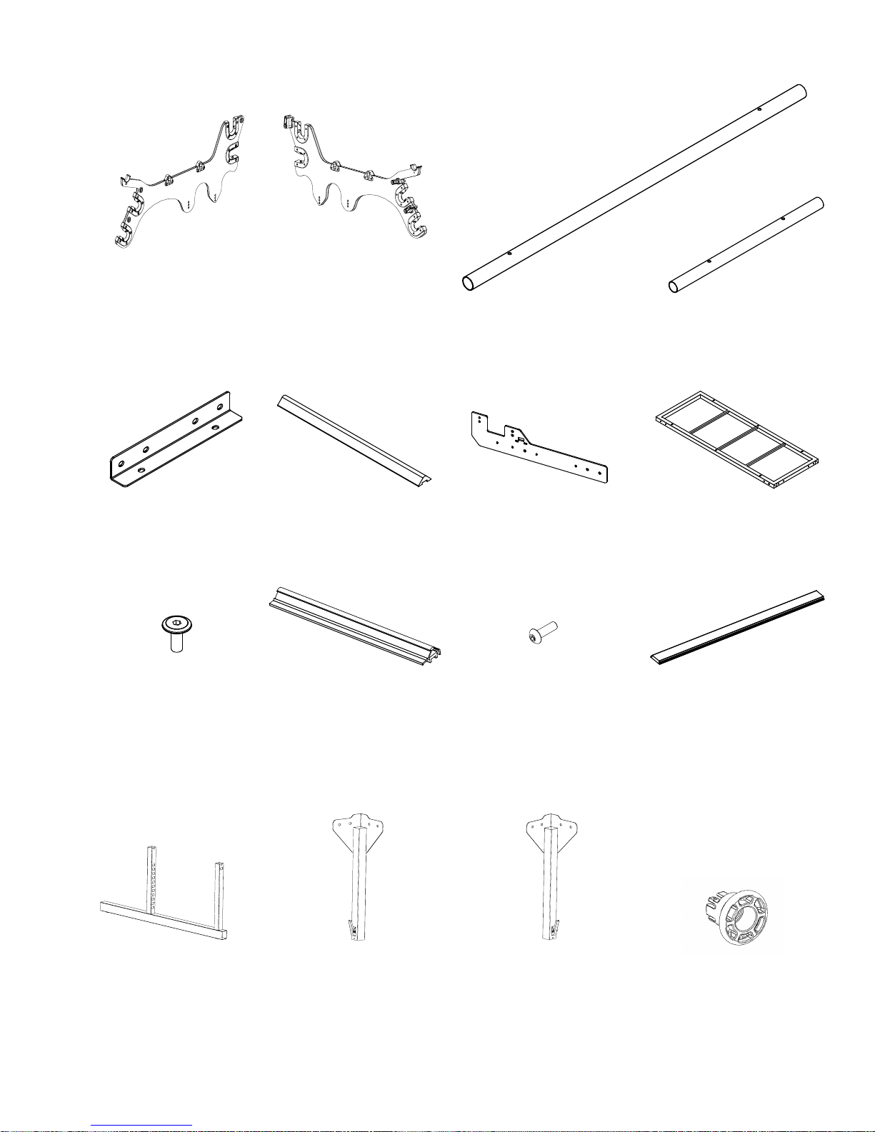
Baby Lock Kinetic Frame Parts & Hardware List
Left Pole Bracket
Assembly (1)
QF05314-100
Box 2
Table Splice (2)
QF05300-05
Box 2
Right Pole Bracket
Assembly (1)
(Comes with latches not
assembled)
QF05314-200
Box 2
Track Support Coupler (2)
QF09318-03
Box 2
Pole Section, 5-foot (10)
QF05300-701
Box 3
Support Rail (2)
QF05300-150
Box 3
Pole Coupler (5)
QF09318-702
Box 3
Table Section with Plastic
Top 5-foot (2)
QF05300-300
Box 1
M6 x 12mm
Socketed Washer
Head Cap Screw, Track
Support Screws (12)
(Comes in track supports
on table sections)
QF09318-303
Box 1
Lower End Leg (2)
QF09318-401
Box 2
Track Support, 5-foot (4)
(Comes on table sections)
QF05300-02
Box 1
Upper End Leg A (2)
QF05314-402
Box 2
M5 x 8mm
Socketed Button Head
Cap Screw: Track Support
Coupler Screws (12)
QF09318-304
Box 2
Upper End Leg B (2)
QF05314-403
Box 2
Baby Lock Kinetic Frame Assembly Instructions 3
Track, Black, 10-foot (4)
QF05300-04
Box 2
Pole Keeper (2)
QF05300-01
Box 2
Page 4
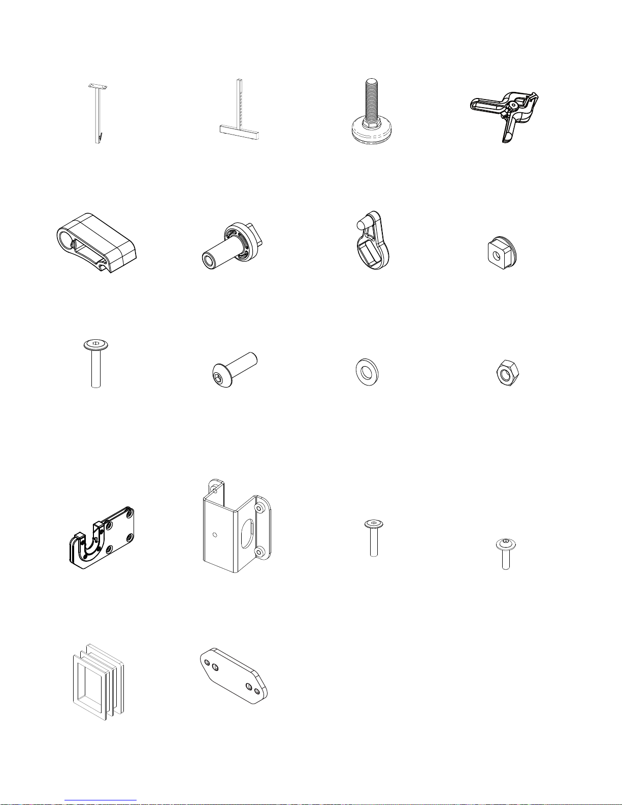
RATCHET STOP HOLDER
QF09318-205
Fig. 10-2
QF09318-105
Baby Lock Kinetic Frame Parts & Hardware List
Upper Middle Leg (1)
QF05314-602
Box 2
Ratchet Stop (3)
QF09318-203
Box 2
M6 x 48mm
Socketed Washer Head
Cap Screw: Ratchet Stop
Screw (3)
QF09318-204
Box 2
Lower Middle Leg (1)
QF09318-601
Box 2
Ratchet Stop Bushing (3)
QF09318-201
Box 2
M8x25mm
Socketed Button Head Cap
Screw (For thick metal on
support rail) (12)
QF09318-06
Box 2
Leveling Glide (6)
QF09318-108
Box 2
Ratchet-Stop Holder (3)
QF09318-205
Box 2
Metal Washer, M8 (5)
1 extra
QF09318-09
Box 2
Bungee Clamps (4)
QF09318-110
Box 2
Ratchet Stop Mount (3)
QF09318-202
Box 2
Nut, M8 Nylon Lock (4)
QF09318-08
Box 2
Batting Bar Bracket
Assembly (w/clamp) (2)
QF05300-460
Batting Bar
Bracket Clamp (2)
QF05300-465
Box 2
Leg End Cap Come
Preinstalled in Legs (6)
QF09318-406
Shim Kit (6)
BLQF-SK (For 5- and 7-foot
frame congurations)
Box 2
4 Baby Lock Kinetic Frame Assembly Instructions
Box 2
M6 x 25mm
Socketed Washer Head
Cap Screw: Batting Bar
Bracket Screws (8)
QF05300-113
Box 2
M8x16mm
Socketed Button Head Cap
Screw (25) 2 extra
QF09318-07
Box 2
Page 5
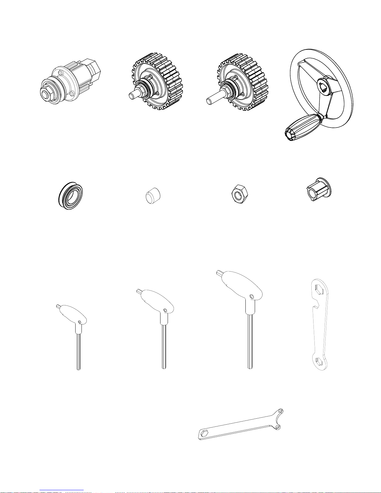
SHORT BOLT RATCHET WHEEL
QF09318-730
QF09318-730
LONG BOLT RATCHET WHEEL
QF09318-730
LONG BOLT RATCHET WHEEL
Baby Lock Kinetic Frame Parts & Hardware List
Fig. 9-2
Fig. 8-1
Fig. 9-4
Fig. 9-3
Pole End Assembly (7)
QF09326
Box 2
Pole End Assembly with
Short Bolt (2)
QF09320
Box 2
Pole End Assembly with
Long Bolt (1)
QF09321
Box 2
Hand Wheel Assembly (1)
QF09325
Box 2
V-Groove Bearing (10)
(Comes on pole end and
ratchet assemblies)
QF09318-705
Box 2
3mm Allen Wrench (1)
QF09318-111
Box 2
Rubber Thread Caps (10)
QF09318-716
Box 2
4mm Allen Wrench (1)
QF09318-112
Box 2
Regular Nut, M10,
Assembly Tool (1)
(To aid with pole end
assembly, see note in
Step 11-4 page 22)
QF09318-717
Box 2
5mm Allen Wrench (1)
QF09318-113
Box 2
Hand Wheel Insert (1)
(May be inside Hand Wheel)
QF09318-713
Box 2
17/13/16mm Wrench (1)
QF09318-114
Box 2
Not Shown Not Shown
Hook & Loop Tape, 10-foot
Assembly Instructions (1)
for poles (3)
QF00665
Box 2
BLKFAI
Box 2
Pole End /10mm Wrench
QF09318-12
Box 2
Baby Lock Kinetic Frame Assembly Instructions 5
Page 6
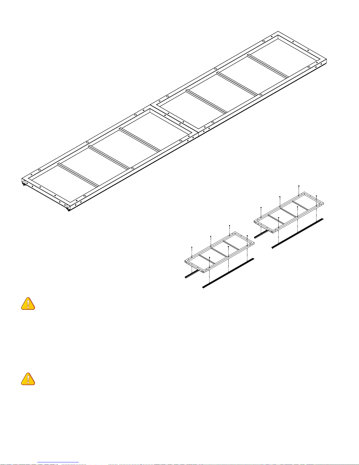
Step 1
Remove Track Supports
Fig. 1-1
Parts needed
(2) table section
Tools Required
4mm Allen wrench (provided)
NOTE: The track support nish could be
damaged if not protected or if placed onto a
rough surface. Handle with care.
1-1: Place the table sections with the track
supports face down onto a protective surface.
(Fig. 1-1)
NOTE: When removing the track supports,
keep them in the same position and orientation
to ensure perfect alignment when they are
replaced.
Fig. 1-2
1-2: Using the 4mm Allen wrench remove
the three screws from each track support and
set the track support aside in a safe place
(Fig. 1-2). Leave the table sections face down
for Step 2-1.
6 Baby Lock Kinetic Frame Assembly Instructions
Page 7
Step 2
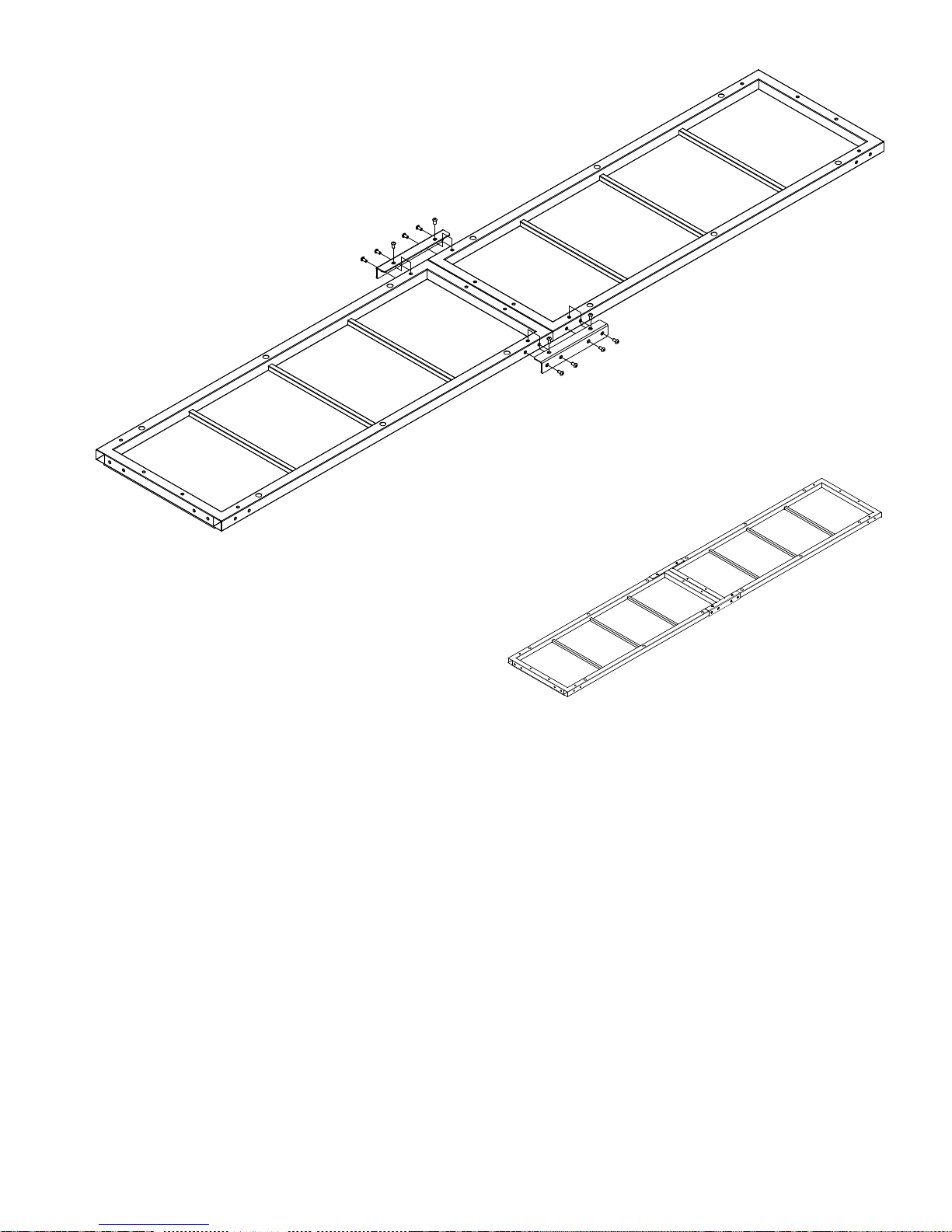
Table Assembly
Fig. 2-1
Parts needed
(2) table section
(2) table splice
(12) M8x16mm socketed button
head cap screw QF09318-07
Tools Required
5mm Allen wrench (provided)
2-1: With the table sections face down (large
round screw holes for track supports up), slide
the two table sections together end to end, as
close as possible. Place a table splice onto the
sections as shown in Fig. 2-1, lining up the
holes in the splice with those in the sections.
Repeat with remaining table splice on the
opposite side of the table sections.
2-2: Place four (4) M8x16mm QF09318-07
through the side of each table splice and nger-
tighten them into the table sections. (Fig. 2-1)
2-3: Finger-tighten two (2) M8x16mm
QF09318-07 through the top of eachtable
splice.
Fig. 2-2
Using the 5mm Allen wrench, tighten the
2-5:
four side screws on each table splice, until the
splice touches the side of the table section, and
then loosen the screws ½ turn.
Using the 5mm Allen wrench, tighten fully
2-6:
the two (2) top screws on each table splice.
Finally, fully tighten the four (4) side screws
on each table splice. (
Fig. 2-2
)
2-4: Pull the two (2) table sections as close
together as possible to remove gap.
Baby Lock Kinetic Frame Assembly Instructions 7
Page 8
Step 3
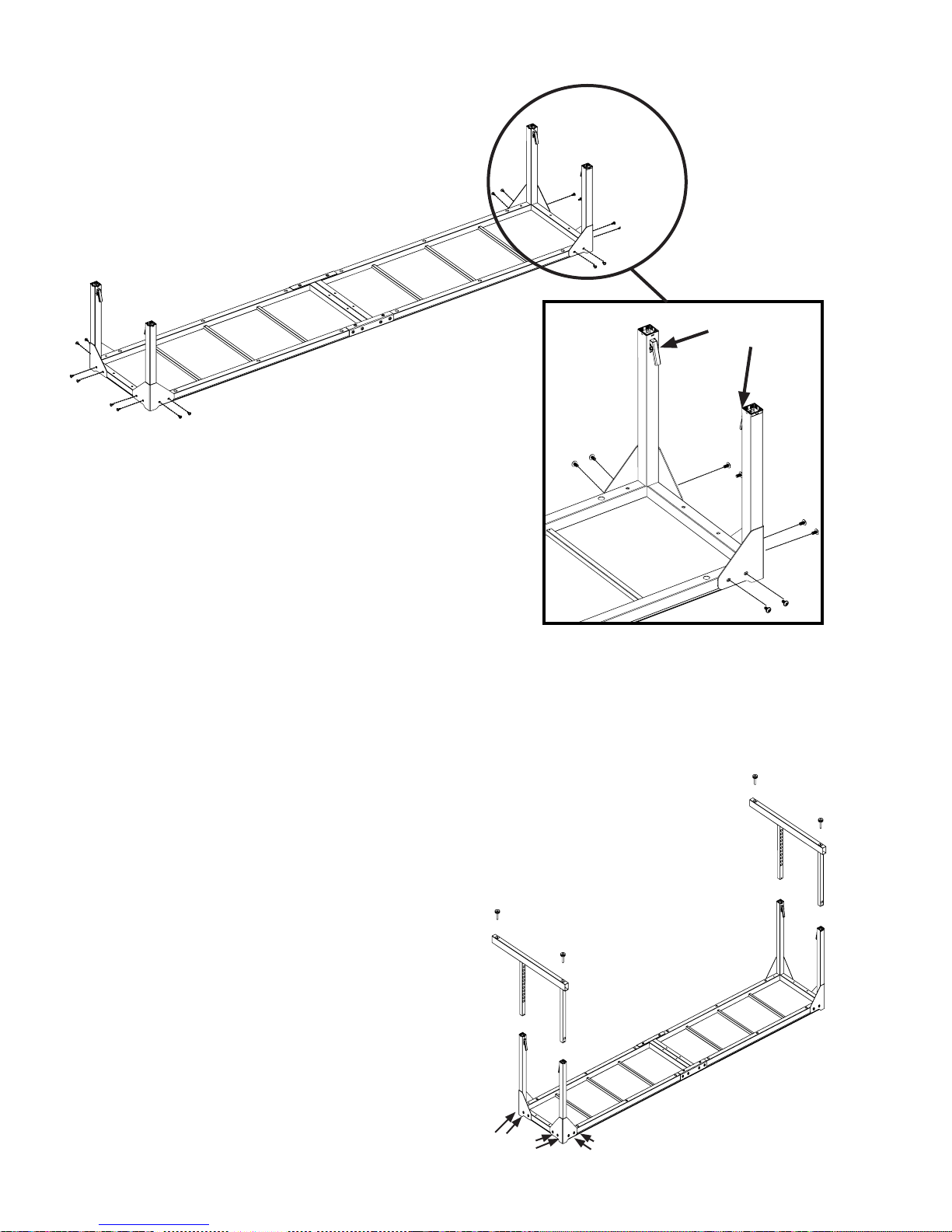
End Leg Assembly
Upper
End Leg B
Upper
End Leg A
Upper End
Leg A
Upper End
Leg B
Fig. 3-1
Height-Adjustment
Latches
Detail 3-1
Parts needed
(1) table assembly
(2) upper end leg A
(2) upper end leg B
(2) lower end leg
(4) leveling glide
(8) M8x16mm socketed button head
cap screw QF09318-07
(8) M8x25mm socketed button head cap screw
Tools Required
5mm Allen wrench (provided)
3-1: With the table on the protective surface,
still facing down, position the upper end legs
A & B so the height adjustment latches face
each other across the short end of the table.
(See Fig. 3-1 and Detail 3.1.)
3-2: Attach each upper end leg to the table
with two (2) M8x16mm screws through the
upper corner leg brackets at front or rear and
with two (2) M8x24mm at the end. Lightly
tighten for now with the 5mm Allen wrench.
8 Baby Lock Kinetic Frame Assembly Instructions
3-3: Slide one (1) lower corner leg onto the
two (2) upper corner legs on each end of the
frame as shown in Fig. 3-2 on the previous
page and Fig. 3-3. Choose the preferred height
of the frame based on the table in Fig. 3-4.
Fig. 3-2
M8x25mm
QF09318-06
at end
M8x16mm QF09318-07
front and rear
Page 9
Step 3
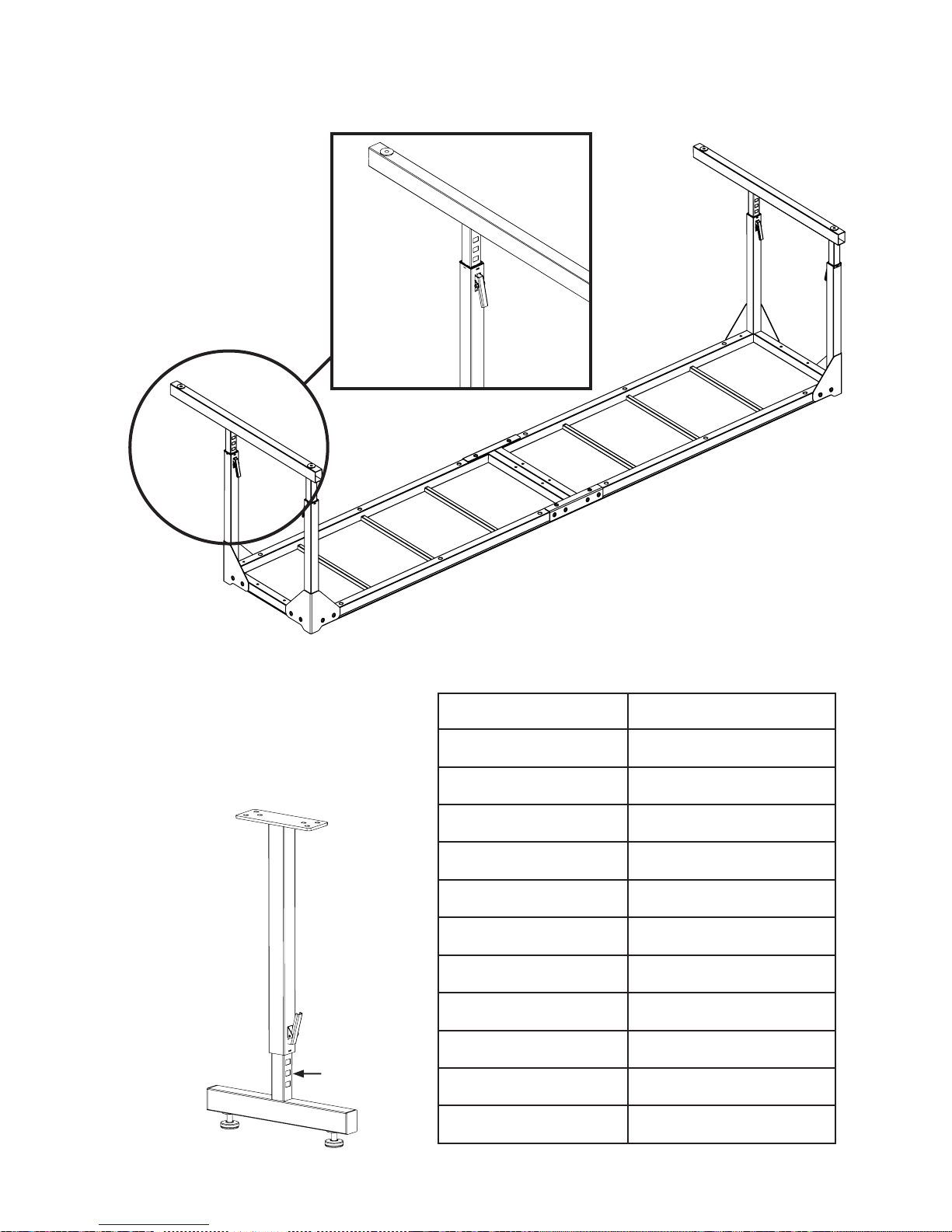
End Leg Assembly (continued)
Detail 3-3
Fig. 3-3
Fig. 3-4 Table of Heights
notches
Ten notches showing 44-inch oor to quilt plane
Nine notches showing 43-inch oor to quilt plane
Eight notches showing 42-inch oor to quilt plane
Seven notches showing 41-inch oor to quilt plane
Six notches showing 40-inch oor to quilt plane
Five notches showing 39-inch oor to quilt plane
Four notches showing 38-inch oor to quillt plane
Three notches showing 37-inch oor to quilt plane
Two notches showng 36-inch oor to quilt plane
One notch showing 35-inch oor to quilt plane
In rst notch up 34-inch oor to quilt plane
Bottom 33-inch oor to quilt plane
Baby Lock Kinetic Frame Assembly Instructions 9
Page 10
Step 3
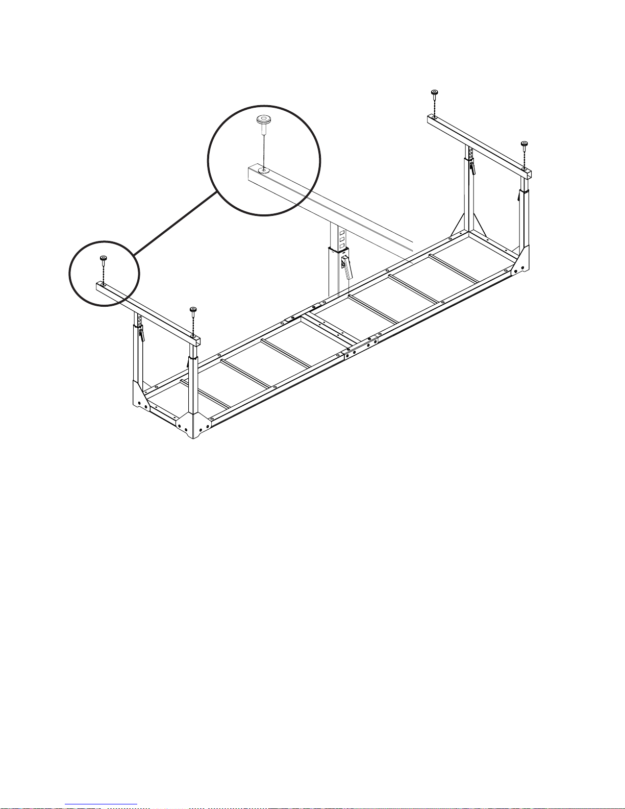
Corner Leg Assembly (continued)
Detail Fig. 3-5
3-4: Thread a leveling glide into each end of
the corner leg assemblies, leaving about 1/2” of
the threads exposed to make it easier to level
the frame later. (Fig. 3-5 and Detail 3-5)
Fig. 3-5
10 Baby Lock Kinetic Frame Assembly Instructions
Page 11
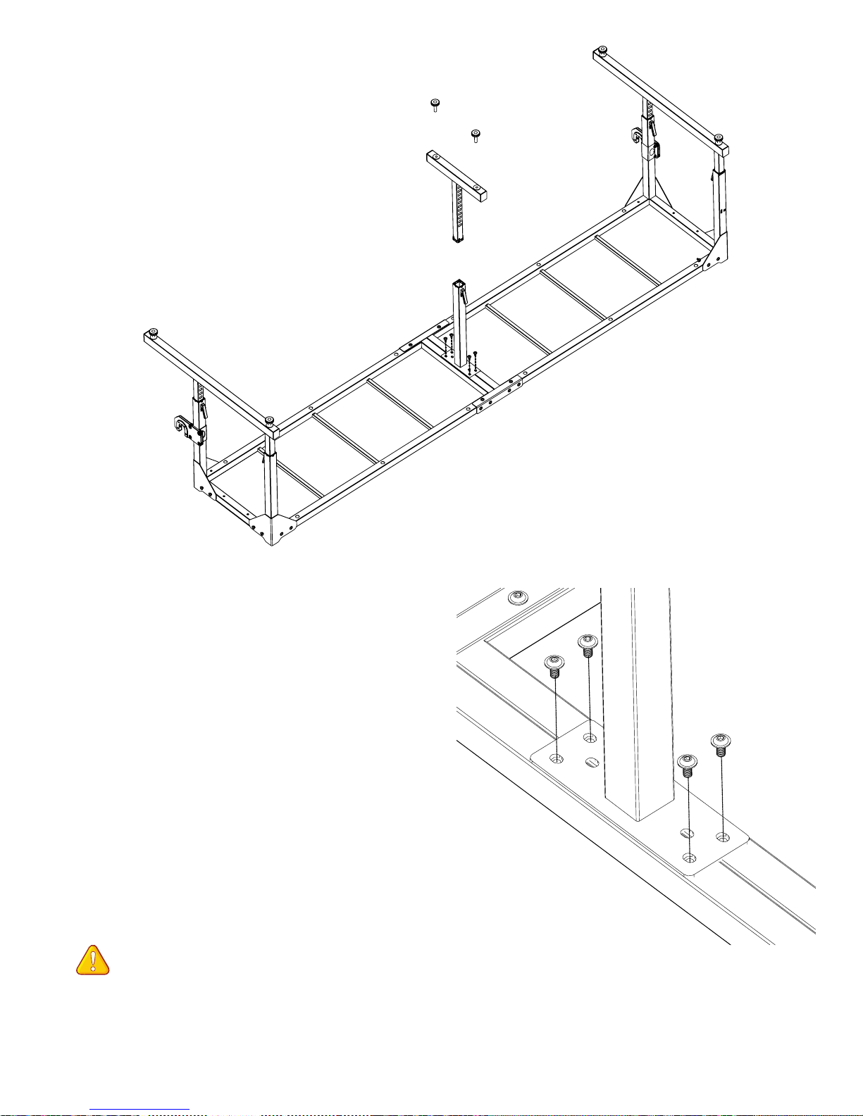
Step 4
Middle Leg Assembly
Fig. 4-1
Parts needed
(1) table assembly
(1) upper middle leg
(1) lower middle leg
(4) M8x16mm socketed button
head cap screw QF09318-07
(2) leveling glide
Tools Required
5mm Allen wrench
4-1: Place the upper middle leg on the center
of the table assembly and thread an M8x16mm
QF09318-07 into each corner of the mounting
plate. (Fig. 4-1 and Detail 4-1) Fully tighten
each screw with the 5mm Allen wrench.
Important note: It is recommended
the latch be towards the rear of the frame as
shown so the latch will not interfere with the
batting on the batting storage pole.
Detail 4-1
Baby Lock Kinetic Frame Assembly Instructions 11
Page 12
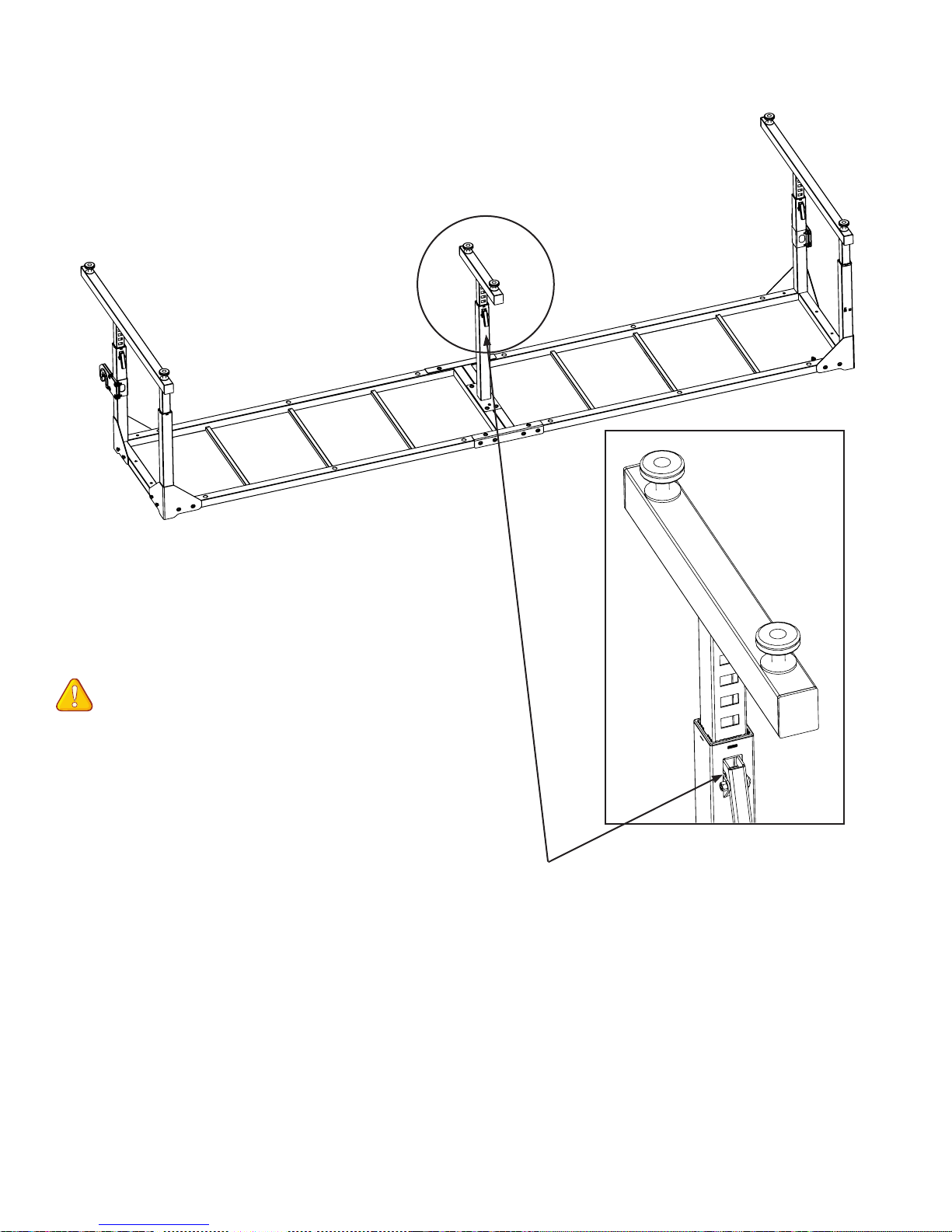
Step 4
Middle Leg Assembly (continued)
Detail 4-2
Fig. 4-2
4-2: Slide the lower middle leg onto the upper
middle legs to the desired height.
Note: It is easier to raise the frame than
lower it once the frame is set upright.
(Fig. 4-2)
4-3: Thread a leveling glide into each end of
the middle leg assembly. (Detail 4-2)
Latch to rear of frame as shown
12 Baby Lock Kinetic Frame Assembly Instructions
Page 13
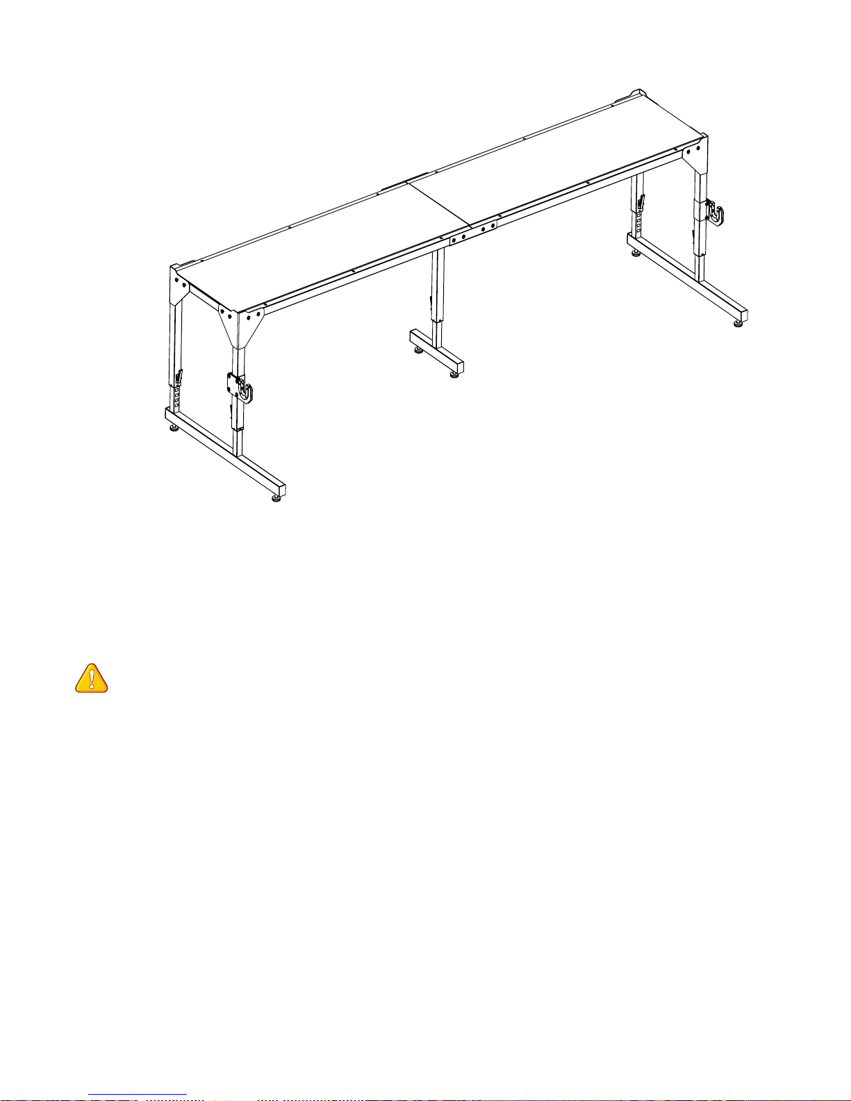
Step 5
Uprighting the Frame
Fig. 5-1
Parts needed
(1) frame assembly
Tools Required
helper
NOTE: The end screws have been
temporarily installed and lightly tightened into
the end of the frame to support the legs while
uprighting it. Care should be taken with the
legs until they are fully tightened. (Fig. 5-1)
5-1: With the help of a second person, lift the
frame into an upright position.
Baby Lock Kinetic Frame Assembly Instructions 13
Page 14
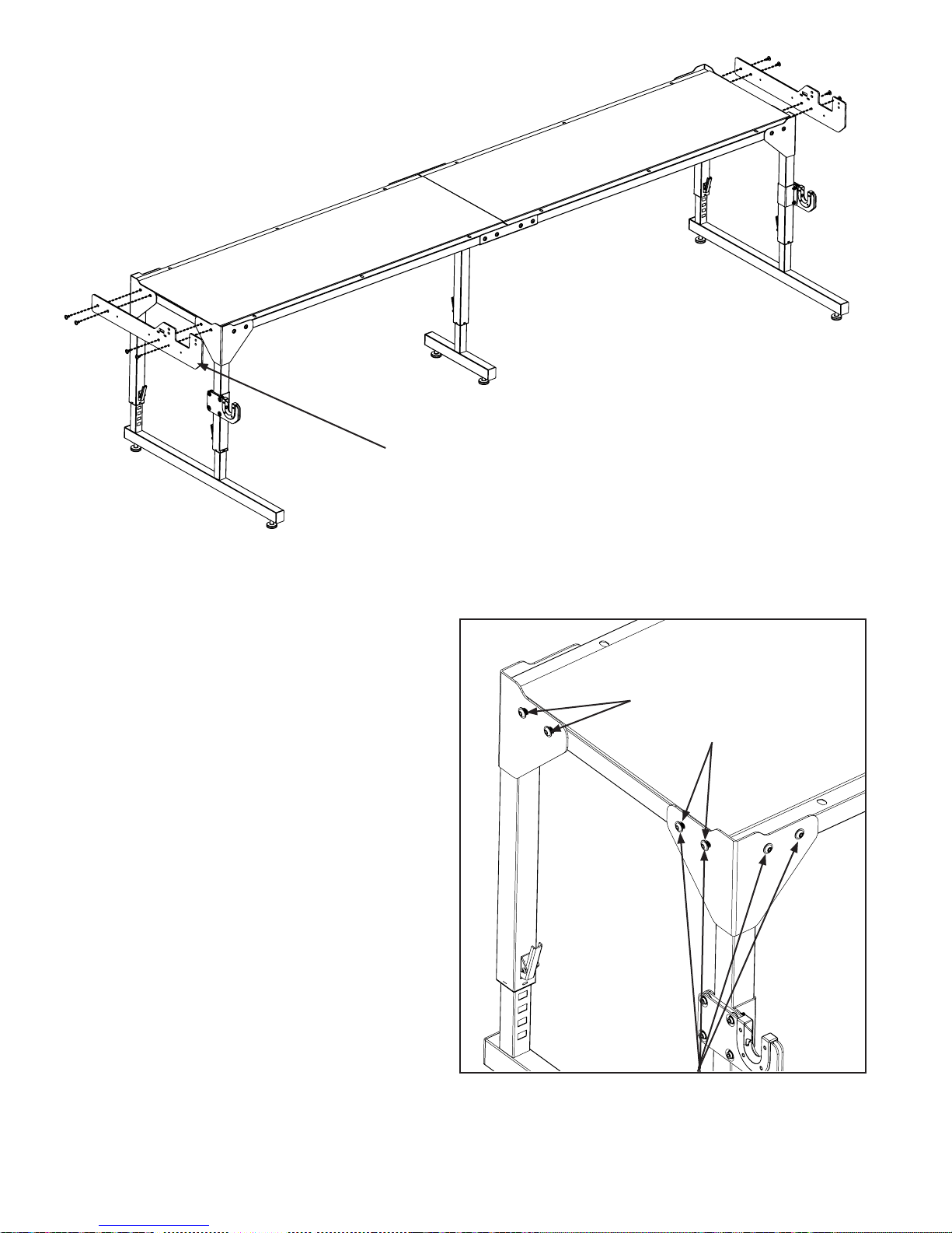
Step 6
Support Rail Assembly
Note the orientation
of the support rail to
the end leg.
Fig. 6-1
Parts needed
(1) frame assembly
(2) support rail
(8) M8x25mm socketed button head cap screw
QF09318-06 (already in frame ends)
Tools Required
5mm Allen wrench (provided)
6-1: Remove the four (4) lightly-tightened
M8x25mm QF09318-06 end screws from the
frame, as shown in Fig. 6-2.
6-2: Align the support rail to the end of the
frame, orienting the rail as shown in Fig. 6-1.
Insert the four (4) M8x25mm QF09318-06
through the support rail and into the frame and
fully tighten with the 5mm Allen wrench.
(Fig. 6-1)
6-3: At this time, fully tighten the remaining
four (4) screws at the upper corner legs into the
frame. (Fig. 6-2)
Remove these lightlytightened end M8x25mm
QF09318-06 to prepare
for placing the support
rail (Step 6-1).
Fig. 6-2
6-4: Repeat steps 6-1 through 6-3 to attach
the remaining support rail to the other end of
the frame.
14 Baby Lock Kinetic Frame Assembly Instructions
Tighten these M8x16mm
QF09318-07 at each corner in Step 6-3.
Page 15
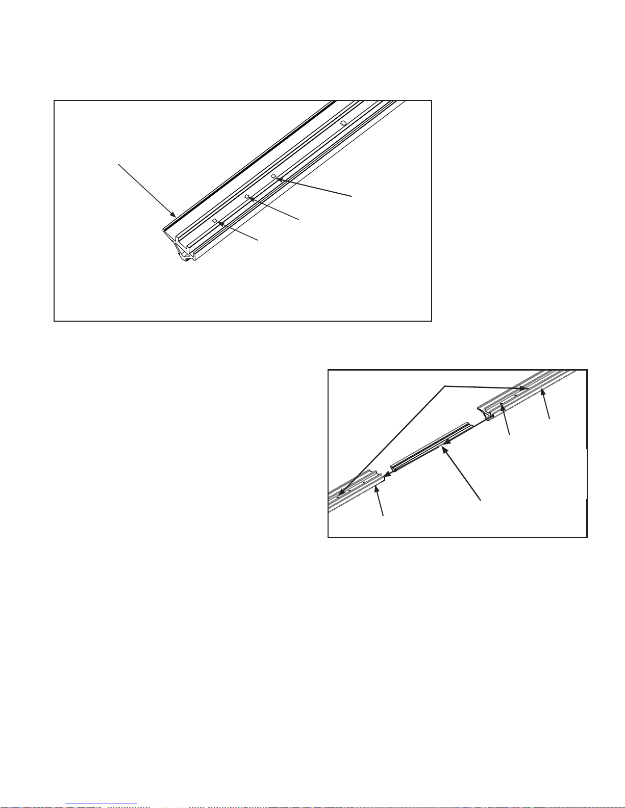
Fig. 5-2
Fig. 5-3
QF09318-02
Step 7
Track Assembly
Place the track support
upside down with the lip
toward the outside of the
table.
Fig. 7-1
Track Support shown upside down.
Third Hole for
stop screws
Second Hole
First Hole
Parts needed
(1) frame assembly
(4) track support
(2) track support couple
(12) M5x8mm Socketed Button Head
(12) M6x12mm Socketed Washer Head Cap
(4) Black Track
Tools Required
3mm Allen wrench (provided)
4mm Allen wrench (provided)
7-1: Place the four (4) track supports, removed
earlier, on the frame assembly top with the
screw holes up and the wide lip of the supports
facing the outside of the table.
(Fig. 7-1)
7-2: Check inside the ends of the track
supports for burrs or debris and remove all
foreign matter from the inside.
Cap Screw QF09318-304
Screw QF09318-303
Stop Screws M5 x 8mm SBHCS QF09318-304
in Third Hole
End Section
First Hole
Coupler
Fig. 7-2
End Section
7-3: To prepare for joining the sections
together, screw one M5x8mm QF09318-304
into the third hole from the splice end of each
section to serve as a stop screw. (Figs. 7-1,
7-2) Fully tighten the screw with the 3mm
Allen wrench. This will help align the coupler
properly into the two track support sections
when joined.
7-4: Insert a coupler into one prepared end of
one track support section up to the stop screw.
Thread an M5x8mm QF09318-304 into the rst
and second hole and lightly tighten as shown
in Fig. 7-2.
Baby Lock Kinetic Frame Assembly Instructions 15
Page 16
Step 7
Track Assembly (continued)
Insert the other end of the coupler into second
prepared track support section. Hold the two
adjoining track support sections tightly together
and thread an M5x8mm QF09318-304 into
the rst hole of the second track support and
lightly tighten. You may need to gently rock
the track support to seat the coupler. Insert the
second screw into the track supports, align and
tighten. Once aligned, fully tighten all M5x8mm
QF09318-304.
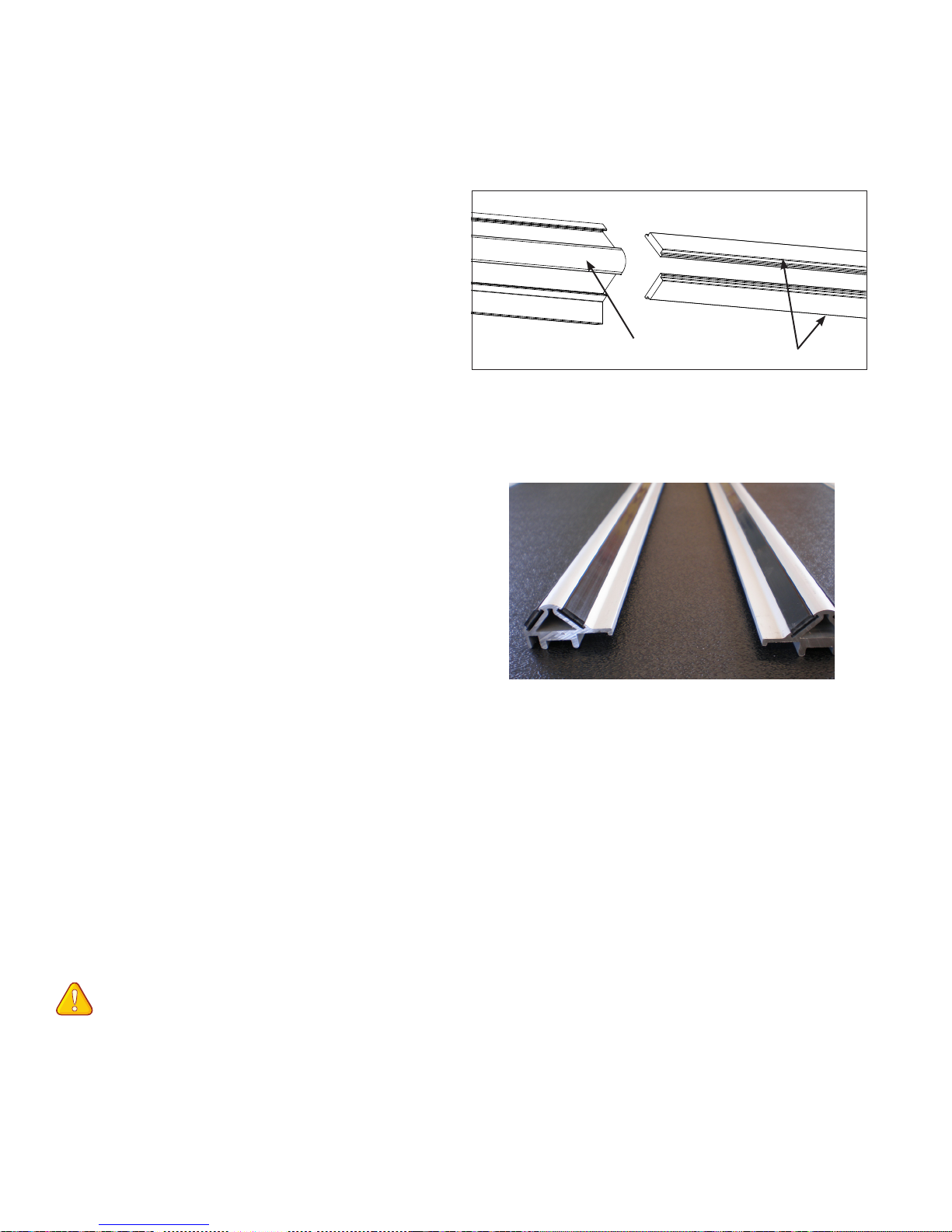
7-5: Insert a plastic track completely into one
side of the aluminum track supports (Fig. 7-3).
The plastic track should slide into the track
support easily. If a plastic track binds slightly,
try backing it out a little, then try pushing it
further. If the plastic binds badly, check the
track supports for debris, burrs, misalignment
or damage. In same manner, insert plastic track
in other side of track support.
7-6: Repeat Steps 7-2 through 7-5 to make the
second track.
Track Support
Plastic Track
Fig. 7-3
Wider
shoulders
to inside
Fig. 7-4
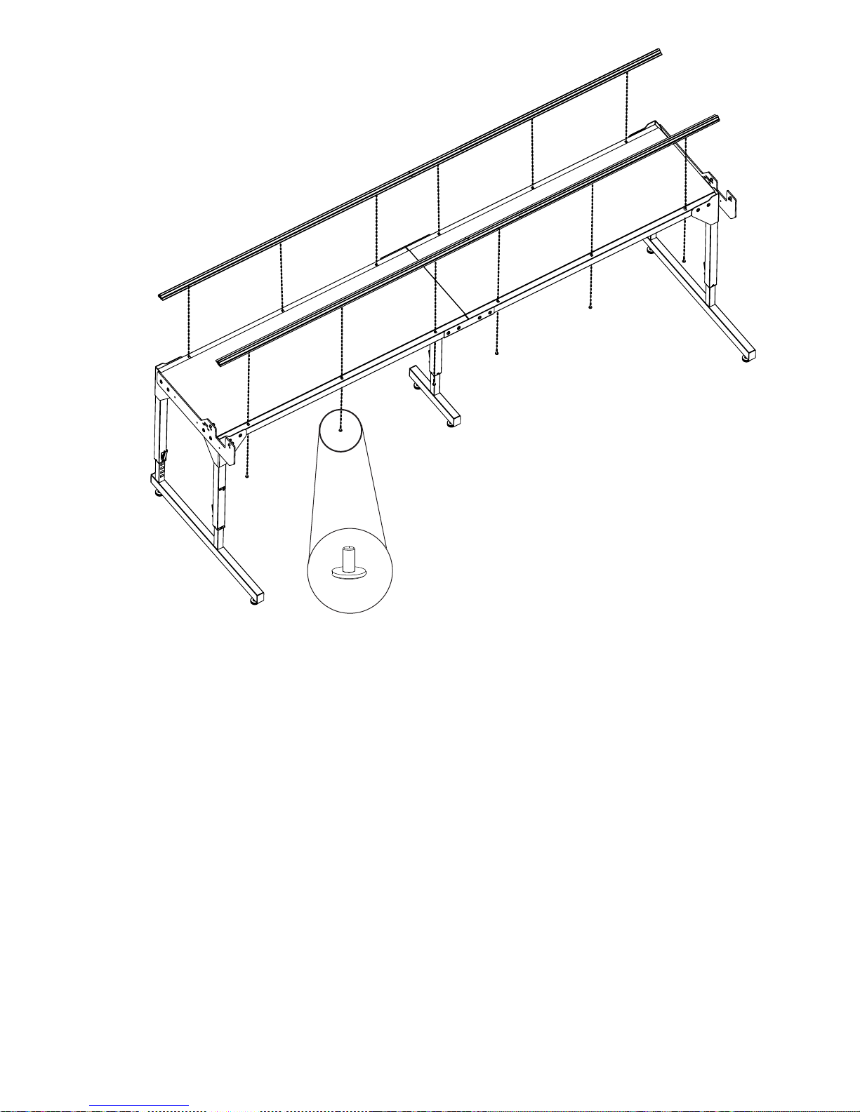
7-7: Attach Tracks. Secure one assembled
track to the back of the quilting frame. Line up
the track support by holding it tightly against
the plastic table top as you secure it to the
frame, using six (6) M6x12mm QF09318-303
as shown in Fig. 7-5 and Detail 7-5 on next
page. Do not tighten screws at this time. They
need to be loose to accommodate adjustments
in the next step. In same manner, attach the
remaining track support to the front of the
frame using six (6) M6x12mm QF09318-303.
NOTE: The extrusions have a wider
shoulder on one edge of the track. This
shoulder is to be placed toward the inside of
the table over the edge of the black plastic
tabletop. (Fig. 7-4)
7-8: Align Tracks. Place the carriage on the
tracks at one end of the table. Roll back and
forth along the length of the table, establishing
the distance between the tracks, taking care to
check that the wheels are engaging the track
on both the front and the back of the carriage.
Move both tracks in tandem to the back of the
table as far as possible. (Slots in the table allow
this movement – if you have not tightened the
screws too tight.) Double-check that the back
track is straight along the back edge of the
table. Fully tighten the screws in the back track
only for now.
16 Baby Lock Kinetic Frame Assembly Instructions
Page 17
Step 7
Track Assembly (continued)
Fig. 7-5
Detail 7-5
7-9: Place the machine onto the carriage and
again, roll it the entire length of the frame,
working the tracks into the wheels as you go.
Lightly tighten the front track support screws as
you move down the table. Check the carriage
to verify that it rolls smoothly and that both
ends of the carriage are engaging the tracks.
If you nd a section of track where the carriage
rocks back and forth when the machine is
moved all the way forward or back, loosen the
front track support screws, adjust the front
track until the carriage rolls smoothly and does
not rock, then re-tighten the front track screws.
7-10: Finally, fully tighten the front track
screws to the table.
Baby Lock Kinetic Frame Assembly Instructions 17
Page 18
Step 8
Ratchet Stop Assembly
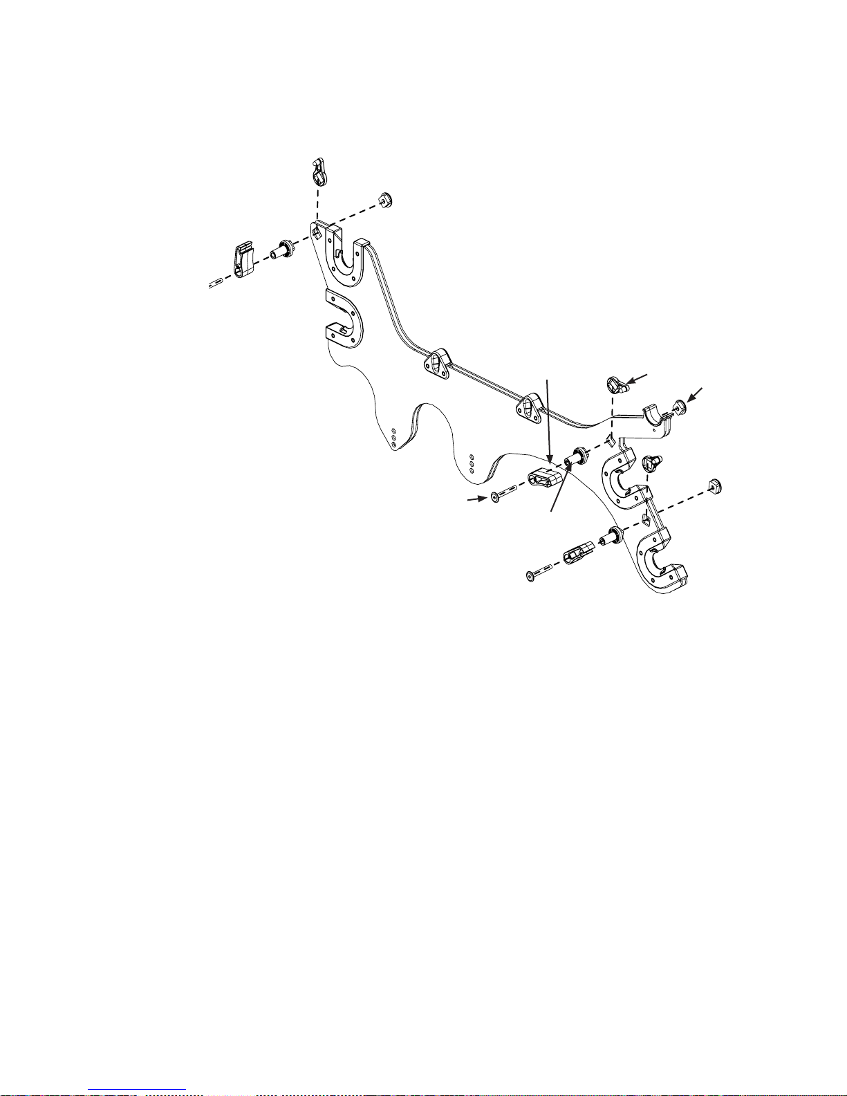
Parts needed
QF09318-204 Screw
(1) open-hole pole bracket (right)
(3) M6x48mm socketed washer head
cap screw QF09318-204
(3) ratchet-stop
(3) ratchet-stop bushing
(3) ratchet-stop mount
(3) ratchet-stop holder
Tools Required
4mm Allen wrench (provided)
8-1: Identify the open-hole pole bracket
(right bracket) and the plugged-hole pole
bracket (left bracket). Set the plugged-hole
pole bracket aside at this time. (Fig. 8-1)
8-2: Place one ratchet-stop catch between the
two metal pieces at the back of the open-hole
pole bracket, with the stop nub facing inside,
as shown in Fig. 8-1 and Details 8-1a,
8-1b, and 8-1c found on the next page. If the
ratchet-stop holder will not t, loosen the two
bearing screws nearest the square hole. Slide
in the ratchet-stop holder and re-tighten
when nished.
Stop
Bushing
Holder
Mount
Fig. 8-1
8-3: Following the parts order shown in
Fig. 8-1, thread one M6 x 48mm QF09318-204
through a ratchet-stop, ratchet-stop bushing,
pole bracket (with ratchet-stop holder inserted)
and nally into the ratchet-stop mount. Pay
close attention to the orientation of the ratchetstop. Tighten with the 4mm Allen wrench
until the ratchet-stop-holder nub holds the
ratchet-stop.
8-4: In same manner, attach the remaining
ratchet-stops and ratchet-stop catches to the
front of the pole bracket, paying attention to
the orientation of the ratchet-stops (Figure
8-1, Details 8-1a, Details 8-1b and 8-1c)
to create the right pole bracket.
18 Baby Lock Kinetic Frame Assembly Instructions
Page 19
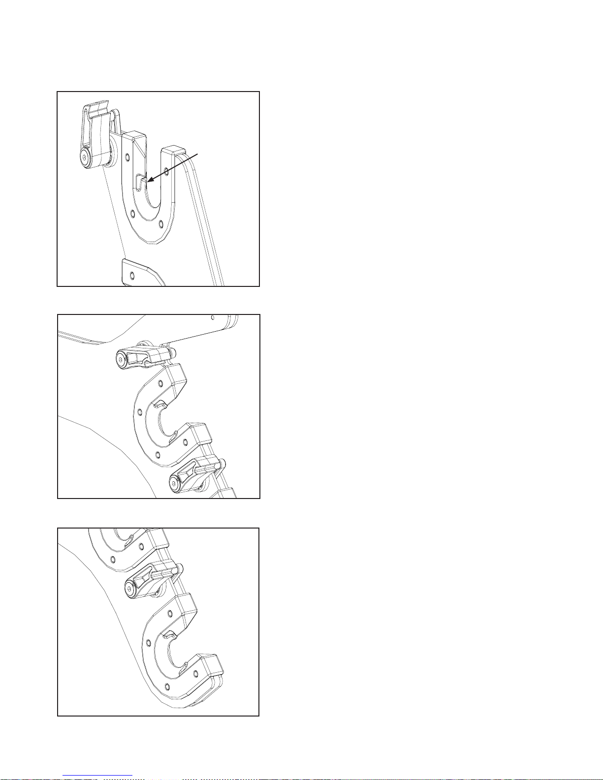
Step 8
Ratchet Stop Assembly (continued)
Finger
Detail 8-1a
Detail 8-1b
Detail 8-1c
Baby Lock Kinetic Frame Assembly Instructions 19
Page 20
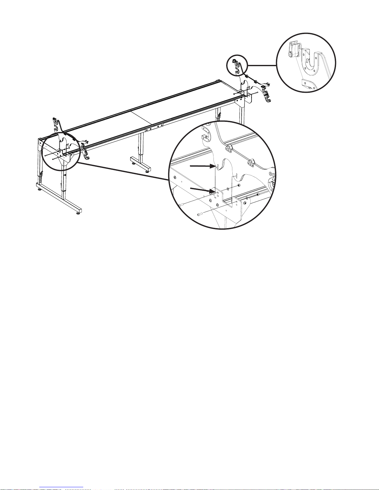
Step 9
Pole Bracket Assembly
Detail 9-2
Use
Center Hole
Use
Top Hole
Parts needed
(1) frame assembly
(1) pole bracket assembly with latches (right)
(1) pole bracket assembly without latches (left)
(4) M8x25 socketed button head cap screw
QF09318-06
(4) M8 at washer QF09318-09
(4) M8 lock nut QF09318-08
Tools Required
5mm Allen wrench (provided)
17/13mm wrench (provided)
9-1: Slide the left pole bracket assembly down
over the support rail on the left frame side
front. The pole bracket should straddle the
support rail. Attach the pole bracket assembly
using two M8x25mm QF09318-06.
Detail 9-1
The Baby Lock Kinetic Quilt Frame pole
brackets have 2 sets of 3 mounting holes to
attach them to the support rails. The center
hole in the 3 holes is normally the optimum
position to install the pole brackets. This hole
normally lines up with the top hole in the
support rails. The support rails have 2 sets of
2 holes for mounting the pole brackets. The
top hole is to be used when using the Baby
Lock Regalia standard carriage and the
bottom set of holes is to be used when using
the Pro-Stitcher carriage. The extra 2 holes on
the pole brackets are for adjustment of the pole
brackets, up or down. The pole bracket can be
adjusted 7/16” up or down from the center hole
if needed. On the end of each screw, slide a at
washer followed by a lock nut, as shown
in Detail 9-1.
Thread the screws through the center
hole of the pole bracket and the top hole
of the support rail from the outside to the
inside of the frame (Detail 9-1).
20 Baby Lock Kinetic Frame Assembly Instructions
9-2: Visually level the pole bracket assembly
and fully tighten the two screws with the 13mm
wrench and 5mm Allen wrench.
9-3: Repeat Steps 9-1 and 9-2 to attach the
right pole bracket assembly, making sure the
ratchet stops are on the inside of the frame.
(Detail 9-2)
Page 21
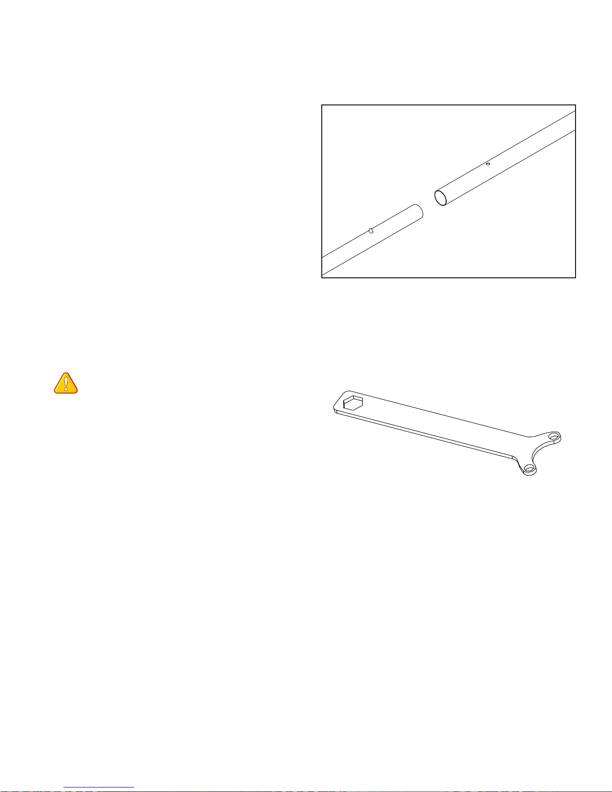
Step 10
Fig. 9-3
Pole Coupler Assembly
Parts needed
(10) pole sections
(5) pole couplers
10-1: Join two pole sections together by
inserting a pole coupler into the end of one
pole section (as shown in Fig. 10-1),
depressing the spring button as it slides in.
Continue sliding until the spring button pops
out of the hole in the pole section. Repeat
to add the second pole section to the rst to
complete one pole assembly.
10-2: Using the remaining pole couplers and
pole sections, repeat Step 10-1 to complete
three more pole assemblies.
Pole Section
Pole Coupler
Fig. 10-1
Fig. 8-1
Special tool for pole end attachment
Note: A pole end wrench is provided to
aid in holding the pole ends without ratchets
and a regular M10 nut is provided for the pole
ends with ratchet wheel assemblies, if you have
trouble holding the pole end while tightening
the pole end into the pole.
Place the smalll holes on the wrench over
two of the protruding tabs on the pole ends
to help hold the pole ends while tightening
the lock nut.
Fig. 10-2
Baby Lock Kinetic Frame Assembly Instructions 21
Page 22
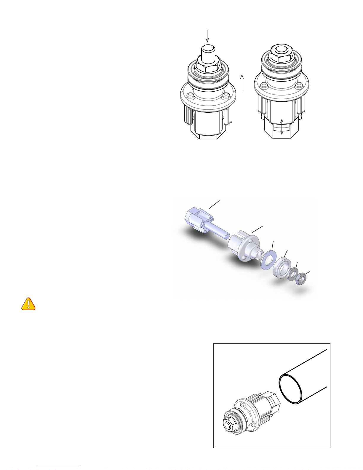
Fig. 9-4
Fig. 9-2
Fig. 8-1
Fig. 9-4
Fig. 9-3
Step 11
Pole End Assembly
Parts needed
(5) pole assembly
(7) pole end
(2) short-bolt ratchet wheel assembly
(1) long-bolt ratchet wheel assembly
(1) hand wheel assembly
(1) hand wheel insert
Tools Required
17/13mm wrench (provided)
Pole end/10mm wrench (provided)
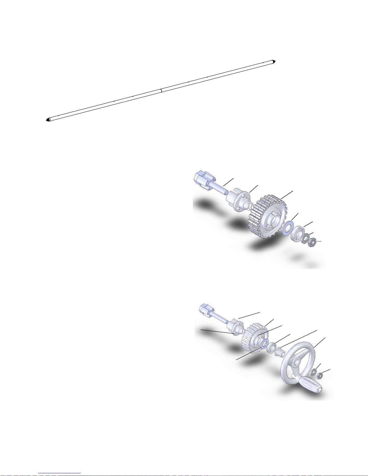
11-1: Check one pole end to ensure that it
matches Fig 11-1 and 11-3.
11-2: Loosen the nut on the pole end until it
reaches the end of the bolt (Fig. 11-2).
Loosen nut then push
Pole End
Fig. 11-1
Inside Pole End Short Bolt Wedge
Wedge
Slides Out
Fig. 11-2
11-3: Holding onto the outside pole end, push
the nut end of the bolt towards the opposite
end of the assembly (Fig. 11-1), until the pole
end short-bolt wedge slides out (Fig. 11-2).
This makes the outside diameter of the pole
end smaller and ready to be inserted into the
end of the pole assembly.
11-4: Repeat Steps 11-1 to 11-3 to prepare the
remaining four (6) pole ends for insertion.
NOTE: A pole end wrench is provided to
aid in holding the pole ends without ratchets
and a regular M10 nut is provided for the pole
ends with ratchet wheel assemblies, if you have
trouble holding the pole end while tightening
the pole end into the pole.
11-5: Slide one pole end into the end of one
pole assembly as shown in Fig. 11-4. Check
that the pole end is inserted completely into the
pole assembly.
Outside Pole End
Large Washer
V Bearing
Small Washer
Lock Nut
Pole End
Pole End assembly comes pre-assembled. Exploded diagram is
for reference only.
Fig. 11-3
11-6: Completely tighten the nut, using the
17/13mm wrench, while holding the pole end
assembly tightly into the open end of the pole.
This will expand the outer pole end, ensuring a
tight t into the pole.
22 Baby Lock Kinetic Frame Assembly Instructions
Fig. 11-4
Page 23
Step 11
Fig. 9-6
Fig. 9-6
Pole End Assembly (continued)
Batting Storage & Idler Pole
X2
Fig. 11-5
11-7: Repeat steps 11-5 and 11-6 to add a
second pole end to the other open end of the
pole assembly just built and one pole end to
each of the remaining 3 pole assemblies
(Fig. 11-5). Repeat the process and set the
two poles with two pole ends aside as the
batting storage pole and the idler pole.
Short-Bolt Ratchet-Wheel Assembly
11-8: Check the short-bolt ratchet wheel
assembly to ensure that it matches Fig. 11-6.
11-9: Loosen the nut at the end of the short-
bolt ratchet wheel assembly until it nearly
reaches the end of the bolt.
11-10: Holding onto the outside of the pole
end, push the nut end of the bolt towards the
opposite end of the assembly until the inside
pole end short-bolt wedge slides out (in similar
fashion to Step 11-3). This makes the outside
diameter of the outside pole end smaller and
ready to be inserted into the end of the pole
assembly.
Inside Pole End Short Bolt Wedge
Short Bolt Wedge
Outside Pole End
Short-bolt ratchet assembly comes
pre-assembled. Exploded diagram is
for reference only.
Outside Pole End
Ratchet Wheel
Tab
Long Bolt Ratchet
Wheel and Hand
Wheel Assembly
Large Washer
Ratchet Wheel
Large Washer
Hole
V Bearing
V Bearing
Small Washer
Hex Nut
Fig. 11-6
Hand Wheel
Insert
Hand Wheel
Small Washer
Lock Nut
Long-Bolt Ratchet-Wheel Assembly
11-12: Add the hand wheel assembly and
hand wheel insert as shown in Fig. 11-7,
aligning the three tabs on the hand wheel insert
with the three notches on the outside pole end.
If the three tabs are not properly aligned, the
hand wheel will spin freely, independent of
the pole.
Long bolt ratchet wheel assembly comes pre-assembled
without hand wheel and hand wheel insert. Exploded
diagram is included for reference.
Fig. 11-7
Baby Lock Kinetic Frame Assembly Instructions 23
Page 24
Step 11
Pole End Assembly
(continued)
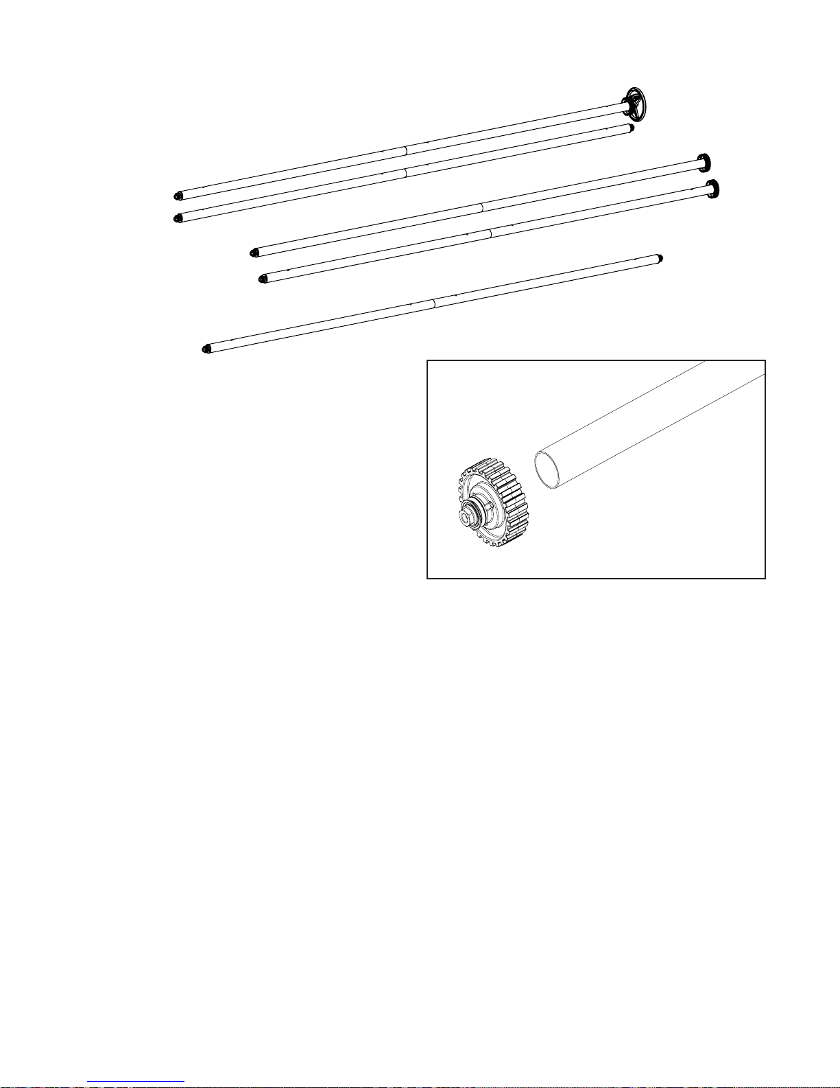
Take-up Pole
Idler Pole
Backing Pole
Quilt-Top Pole
Batting storage pole
Fig. 11-9
11-13: Repeat Step 11-10 to prepare the
long-bolt ratchet wheel assembly for insertion.
Ratchet Wheel and Hand Wheel
Insertion
11-14: Insert one short-bolt ratchet wheel
assembly into the open end of a pole assembly
as shown in Fig. 11-8. Check that the pole end
is inserted completely into the pole assembly.
11-15: Completely tighten the lock nut, using
the 17/13mm wrench, while holding the shortbolt ratchet wheel assembly tightly into the
open end of the pole. This will expand the outer
pole end, ensuring a tight t in the pole. Make
sure all 3 tabs on the outside pole end, align
with the three holes on the ratchet wheel, see
Fig. 11-6 previous page. This completes the
backing pole.
Fig. 11-8
11-17: In same manner, slide the longbolt ratchet wheel assembly and hand wheel
assembly into the open end of the remaining
pole assembly and while holding the complete
assembly tightly into the open end of the
pole, tighten the lock nut, using the 17/13mm
wrench. Check to be sure the hand wheel
engages the ratchet wheel assembly and does
not spin loosely and that the 3 tabs of the
outside pole end align with the 3 holes in the
ratchet wheel. This completes the take-up
pole (Fig. 11-9).
11-16: Repeat Steps 11-14 and 11-15 to
complete the quilt-top pole. Set both poles
aside (Fig. 11-9).
24 Baby Lock Kinetic Frame Assembly Instructions
Page 25
Step 12
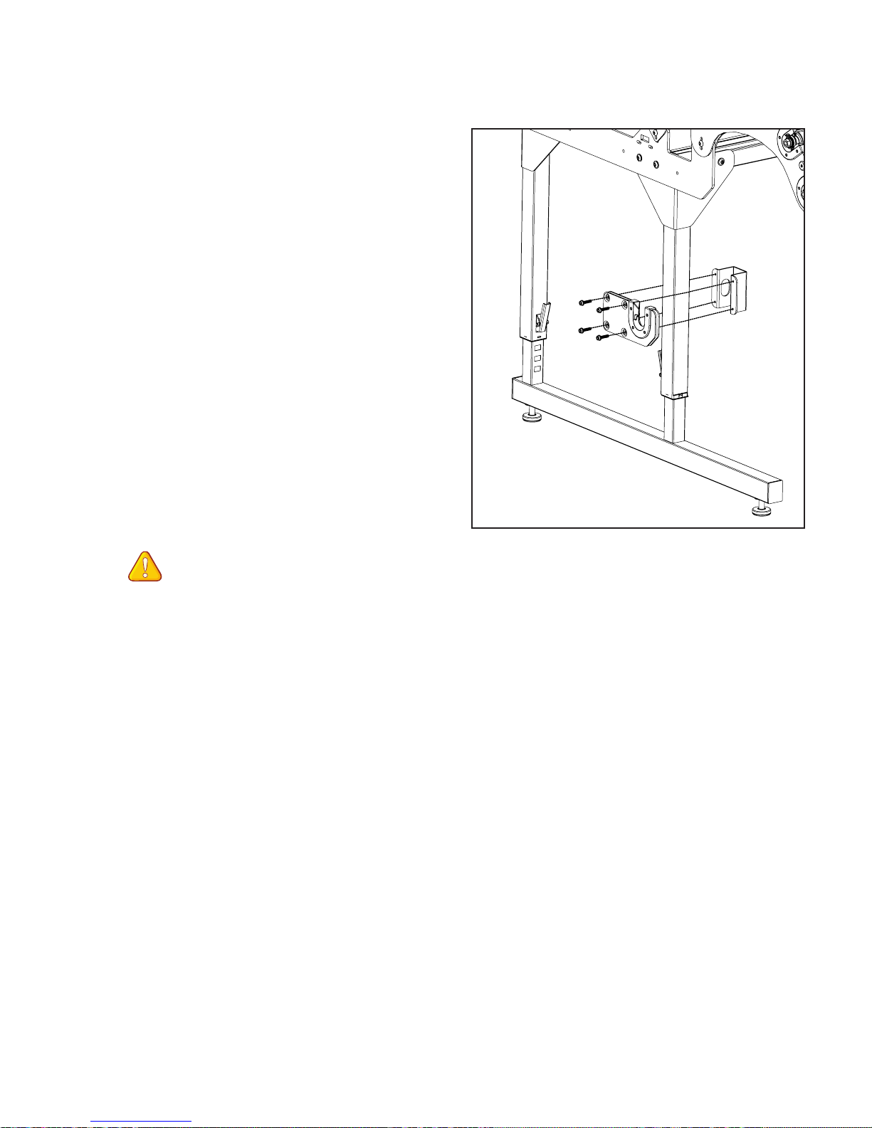
Batting Bar Bracket Assembly
Parts needed
(2) batting bar bracket assembly
(2) batting bar bracket clamp
(8) M6x25mm socketed washer
head cap screw QF05300-113
Tools Required
M4 Allen wrench (provided)
12-1: NOTE: This step includes a
recommendation for the position of the
batting bar bracket. This position can be
changed, depending on the diameter of
the batting roll and the frame-height.
Position the batting bar bracket assembly
on the outside of the front end leg, as
shown in Fig. 12-1. The bracket is installed
approximately in the center of the upper end
leg. Ensure that both brackets are set at the
same height.
12-2: Insert the four (4) M6x25mm QF05300113 through the batting bar bracket assembly
and into the weld nuts on the clamp. Adjust to
the desired height and tighten the screws until
the clamp remains xed at the desired height.
Do not over-tighten the clamp.
Fig. 12-1
12-3: Repeat Step 12-1 and Step 12-2
to install the remaining batting bar bracket
at the other end of the frame. Be sure to set
the batting bar bracket assembly to the same
height on both sides.
Baby Lock Kinetic Frame Assembly Instructions 25
Page 26
Steps 13 & 14
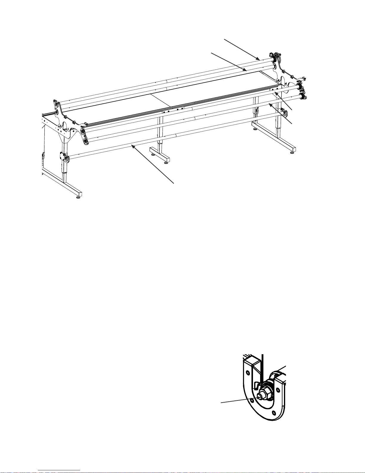
Pole to Frame Assembly
Rubber End Cap Assembly
Take-Up Pole
Idler Pole
Backing Pole
Quilt-Top Pole
Step 13: Pole to Frame Assembly
Parts needed
(1) frame assembly
(1) batting storage pole
(1) quilt-top pole
(1) backing pole
(1) take-up pole
13-1: Place the poles on the frame as shown in
Fig. 13-1. The poles will snap past the plastic
ngers, which are shown in Detail 8-2a.
Step 14: Rubber End Cap Assembly
Batting Storage Pole
Fig. 13-1
Parts needed
(1) frame assembly with poles
(8) rubber end caps
14-1: Slide one (1) rubber end cap onto
the end of each bolt sticking out of the pole
ends, as shown in Fig. 14-1. If the poles
are assembled properly, there should be
approximately 3/8-inch to ½-inch of metal
threads showing beyond the ends of the pole.
26 Baby Lock Kinetic Frame Assembly Instructions
Rubber End Cap
Fig. 14-1
Page 27
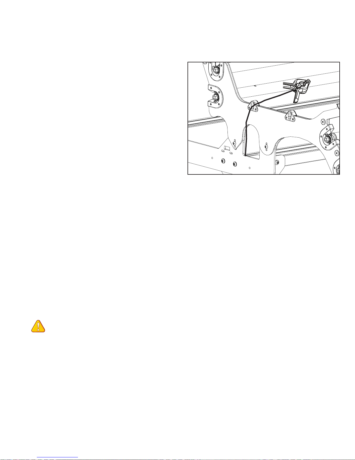
Steps 15 & 16
Bungee Clamp Assembly
Hook & Loop Tape on Pole Assemblies
Step 15: Bungee Clamp Assembly
Parts needed
1- Frame Assembly
4- Bungee Clamps QF09318-110
15-1: Thread the bungee clamp cord from the
inside of the frame through the bungee slot and
then pull the cord in a downward movement to
lock the bungee clamp into place. (Fig. 15-1)
15-2: Follow Step 15-1 for the remaining
three bungee clamps.
Fig. 15-1
Step 16: Hook & Loop Tape on Pole
Assemblies
Parts needed
(1) frame assembly
(1) quilt top pole
(1) backing pole
(1) take-up pole
(3) hook & loop tapes QF00665
Tools Required
measuring tape or ruler (not provided)
scissors (not provided)
NOTE: Take care to stick the hook & loop
tape on straight. This step will determine how
well your quilts load in the future. Use the
Spring Coupler snap buttons as a guide when
aligning the hook & loop tape for best results.
16-1: Prepare to attach the Velcro to the quilt
top pole, backing pole, and take-up pole, by
measuring in 3-inch from each end of the pole.
Peel the backing off the hook & loop tape as
you go and apply to all three poles, starting
at the 3-inch mark and ending at the opposite
3-inch mark. Take care to stick the hook &
loop tape on straight. This step will determine
how well your quilts load in the future. Use the
spring buttons as a guide when aligning the
hook & loop tape for best results. Hint: Attach
the hook & loop tape next to the snap buttons,
not between.
Once the hook & loop tape has been adhered
from one end of the poles to the other, it can
be clipped where the poles meet at the
pole coupler.
Baby Lock Kinetic Frame Assembly Instructions 27
Page 28
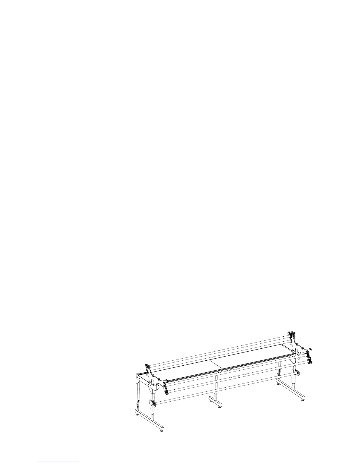
Steps 17 & 18
Attach Leaders
Adjusting Frame Height and Leveling
Step 17: Attach Leaders
Parts needed
(1) frame assembly with hook & loop tape
applied to Poles
(3) leaders (sold separately BLQL)
17-1: Mark the center of the leaders on both
the hook & loop tape and the hemmed edge.
Mark the center of the quilt top pole, backing
pole and take-up pole with a permanent
marker.
17-2: Beginning in the center, align the marks
and attach the leaders to the hook & loop tape
on backing pole and the quilt top pole so the
marked sides of the leaders hang to the center
between the poles.
Beginning in the center, align the marks and
attach the remaining leader so it falls to the
back of the take-up pole.
Ensure that the height-adjustment screws
in each leg are in the same slot and fully
tightened. The rough height setting is done at
the slots in the legs and the ne adjustment
is done at the leveling glides at the bottom of
each leg. The 16mm/10mm wrench is designed
to t the leveling glide.
18-2: Double-check to make sure the frame is
level. Using a spirit level, check and adjust the
frame top to be level in the place where it will
be used, both front to back and side to side,
by adjusting the leveling feet. Double-check
the table top frame to ensure that it is at at
the splice braces and not sagging or high at
the joints. If no spirit level is available, check
the table with machine on the carriage and the
tracks. When the table is level, the machine
should stay where you put it and not roll
forward, back or side to side.
Step 18: Adjusting Frame Height
and Leveling
18-1: Adjust the frame height so that when
standing at the front of the machine with your
hands on the front handle bars, your elbows are
bent at a 90 degree angle. It is recommended
to have a second person lift the frame weight
off the height adjusting screws when you need
to make a height adjustment.
28 Baby Lock Kinetic Frame Assembly Instructions
 Loading...