

Page 1
1
Model Numbers:
Model Numbers:
Model Numbers:
Use & Care Manual
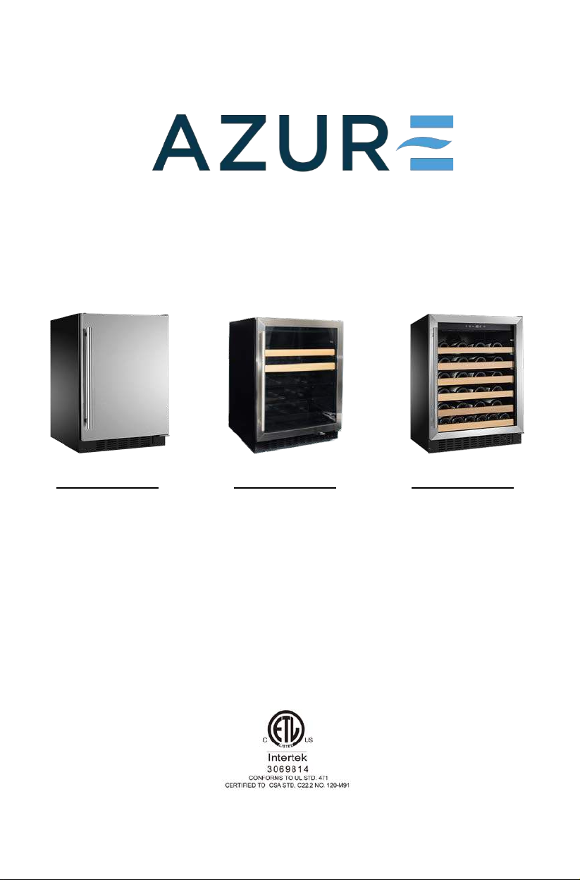
Refrigerators Beverage Centers Wine Centers
A115R-S
A115R-O
A124R-S
A124R-O
A115BEV-S
A115BEV-O
A124BEV-S
A124BEV-O
A115WC-S
A115WC-O
A124WC-S
A124WC-O
Page 2

2
Table of Contents
Page
Safety Precautions 3-6
Warranty 7-8
Installation Instructions 9-12
How to Install and Adjust the Bottom Vent 13
How to Install an Overlay Panel 14
Operating Your Azure Appliances 15-16
Care and Maintenance 17
Troubleshooting Guide 18
Wine Center Parts Listings 19-22
Beverage Center Parts Listings 23-26
Refrigerator Parts Listings 27-30
Page 3
3
Safety Precautions
Your safety and the safety of others are very important.
We have provid ed many imp ortant safet y messages in t his manual for your appliance.
Always read and obey all safety messages.
This is the Safety Alert Symbol. This symbol alerts you to potential hazards that can
cause severe bodily injury or death. All safety messages will follow the Safety Alert
Symbol and either the words “DANGER” “WARNING” or “CAUTION”
Danger means that failure t o heed this safety statement may result in severe injury or
death.
Warning means that failure to heed this safety statement may result in extensive
product damage, serious personal injury, or death.
Caution means that failure to heed this safety statement may result in minor or
moderate personal injury, property or equipment damage.
Page 4
4
Safety Precautions (continued)
For your safety, read
all instructions carefully before operating the a pp lia n c e.
DANGER: When using an electrical appliance, basic precautions should always be followed to reduce the risk of fire, electric shock, and injury to persons.
WARNING: To reduce the risk of fire, electric shock or personal injury,
unplug or disconnect the appliance from the power supply before servicing.
CAUTION: Flammable refrigerant used! When handling, moving and use of the
refrigerator, make sure to avoid either damaging the refrigerant tubing, or
increasing the risk of a leak.
Use this appliance only as described in this m anual. Other uses not recommended may cause fire, electric
shock or personal injury.
This appliance is not intended for use by young children or infirm persons unless they have been adequately
supervise d by a responsible person to ensure that they can use the appliance safely.
Young childr e n should be super vised to en su r e t hat they never play with the ap pliance.
To protect against the risk of electric shock, NEVER IMMERSE the unit, cord, or plug in water or spray any
other liquid.
Unplug the appliance from the plug socket when not in use, when moving from one location to another and
before cleaning.
To disconnect the appliance, grip the plug and pull it from the wa ll outlet. Never pull by the cord.
Never operate the appliance in the presence of explosive and/or flammable fumes.
Never place the appliance or any of its parts near an open flame, cooking or other heating appliance.
Never operate the appliance with a damaged cord or plug, if the product malfunctions, or if it is dropped or
damaged in any manner.
The use of attachments not recommended by the manufacturer may be hazardous.
Place the unit on a dry level surface.
Never operate if the ho using is remov ed or damage d.
A loose fit between the AC outlet (receptacle) and plug may cause overheating and a distortion of the plug.
Contact a qualified electrician to replace loose or worn outlet.
Locate the unit away from direct sunlight and sources of heat (stove, heater, radiator, etc.).
Page 5
5
Safety Precautions (continued)
This appliance is CFC and HFC free and contains small quantities of Isobutane (R600a), an environment ally
friendly coolant.
You must ensure that the cooling circuit is undamaged when installing the appliance. However, if it becomes
damaged, avoid proximity to open fires and heat sources of all kinds. The room in which th e appliance is
located should be venti lated properly and according to state and loc al codes.
Never use an applian ce with a damaged circuit.
Ensure that the ventilation openings to and from a built-in appliance are never blocked or covered.
No liability will be accepted for any damage caused by misuse of the appliance, or as a result of repairs
carried out by unqualified person. In this case neither the warranty nor any other liability claims will apply.
WARNING: Never operate any other electrical appliance inside this appliance.
Never attempt to repair or replace any part of your appliance unless it is specifically recommended in this
manual. All other servicing should be referred to a qualified technician.
Replace all access pan els before operating.
Use two or more people to move and install the appliance. Failure to do so can result in back or other injury.
Never clean appli ance parts with flammable liquids. These fumes can create a fire hazard or explosion. Never
store or use gasoline or oth er flammable vapors and liquids in the vicinity of this or any other appliance. The
fumes can create a fire hazard or explosion.
Never connect or disconnect the electric plug with wet hands.
It is recommended that a separate circuit, serving only your appliance be provided. Use receptacles that
cannot be turned off by a switch or pull chain.
WARNING: To reduce the risk of fire, electric shock or personal injury, unplug or
disconnec t the appliance f rom the power supply before servicing.
Save These Instructions
If you are experiencing problems, check the Troubleshooting Guide at the back of this manual. It lists causes of
minor operating problems that you can correct yourself.
Page 6
6
Safety Precautions (continued)
Disposal of Ol d A p pliance
Dispose of your applian ce packaging properly.
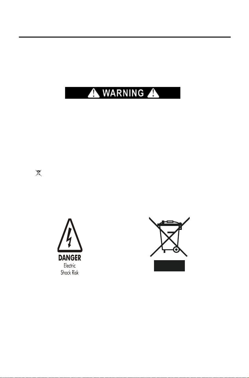
Refrigeration equipment must be properly disposed of in a way which protects the environment. This applies to your old appliance and to your new unit once it has reached the end of its service life.
WARNING: Please ensure that old, worn appliances are rendered unusable before disposal by removing the plug,
cutting the power cable , and removing or destroying any snap fastenings or bolts. You will thus prevent childr en
from locking themselves in the appliance during play (ris k of suffocation) or endangering their lives in any other
way.
Disposal instructi ons:
The appliance must not be disposed with normal household waste collection.
The coolant circuit, particularly the heat exchanger at the back/bottom of the unit, must not be damaged.
The symbol on the product or its packaging indicates that this product is not to be handled as normal
household waste but is t o be taken to a recycling collection point for electrical and electronic goods. By
correctly disposing of this product you are contributing to the protection of the environment. Improper disposal
endangers health and the environment. Further information about the recycling of the product may be obtained
from your town hall or local was te collection department.
Page 7

7
Limited War r a nt y
Products offered through Azure Systems (“Azure”) are manufactured to provide outstanding value, and customer
satisfaction is Azure’s goal for every product. As set forth below, all Azure appliances carry a twelve (12) month
limited warranty on both pa rts and labor, and all refrigerators and freezers carry a thirty-six (36) month limited
warranty on the product’s compressor. Certain exclusions to those warranties may apply.
GENERAL PARTS AND LABOR WARRANTY
Azure warrants to the ori ginal purchaser of every new unit that the cabinet and all of its parts will be free from
defects in material or wor kmanship, under normal and proper use and maintenance service, as specified by Azure ,
and upon pro pe r installation and star t-up, in accordance with the instruction packet supplied with each Azure unit.
This limited warranty expires after twelve (12) months from the date of original purchase, to the original purchaser.
Purchaser's remedy under this limited warranty, is limited to the repair or replacement, at Azure’s sole discretion, of
defective parts or assemblies. All service issues under this limited warranty must be directed to Azure at
[email protected]
approval of or under the dir ection of Azure are not covered under this limited warranty.
COMPRESSOR WARRANTY
Azure warrants that each unit’s hermetically sealed compressor to be free from defects in both material and
workmanship, under normal and proper use and maintenance, for a period of thirty-six (36) months from the date of
original purchase. Compressors determined by Azure to have been defective within this time period will be either
repaired or replaced, at Azure’s sole discretion, with a compressor or compressor parts of similar design and
capacity. This limited compressor warrant y applies only to hermetically sealed parts of the compressor and DOES
NOT apply to any other parts or components, including, but not limited to, th e cabinet, paint finish, temperature
control, refrigerant, metering device, driers, motor starting equipment, fan assembly, or any other mechanical or
electrical component.
All service is sues under th i s limited war r a n ty must be directed to Azure at [email protected]
calling 844-662-9873, and service or repairs preformed without notice to and approval of or under the direction of
Azure are not covered under this limited warranty.
, or by calling 844-662-9873, and service or repairs preformed without notice to and
, or by
LIMITED WARRANTY
As set forth above, Azure’s sole obligation under this limited warranty is limited to either repai r or replacement of
parts, subject to the additional limit ations below. Azure may require the return of defective parts for examination
before issuing repla cement parts. If you are required to return defective parts, shipping charges must be prepaid by
the customer. Upon exam ination, an d to Azur e's determination, if th e original par t is pr o v e n d e fective, Azure ma y
approve your claim and elect to replace such parts without charge. In every instance, the customer is responsible for
the shipping and handlin g of replacement parts. Product repair and/or replacement is the exclusive remedy under th i s
limited warranty.
LIMITATION OF LIABILITY; LIMITATION OF DAMAGES: Azure is not responsible for economic loss; lost
profits; or special, direct, indirect, or consequential damages, including without limit ation, losses or damages arising
from food or product spoi lage claims, whether or not on account of alleged refrigeration failure or any defe ct.
Purchaser’s exclusive remedies are described above.
WARRANTY IS NOT TRANSFERABLE: This warranty is not transferable and applies only in favor of the
original purchaser. Any attempted assignment or trans fer of this limited warranty shall void the limited warranties
described herein and sha ll void all warranties, express or implied, including any warranty of merc hantability or
fitness for a particular p urpose.
OPEN BOX/SCRATCH AND DENT ITEMS: Azure does not cover the costs associated with damage (cosmetic
or otherwise) to a unit that has been purchased as an open box or scratch and dent item. Issues with open box items
must be discussed with the dealer or reseller who initially sold the product.
Page 8

8
Limited Warranty (continued)
IMPROPER USE: Azure assumes no liability for compon ent failure or other damages result ing from improper
usage or installati on or failure to clean and/or maintain the product as set forth in the warranty packet provided with
the product. This limited warranty does not cover the cost of any inconvenience, personal injury or property damage
due to improper use or product failure. This limited warranty also does not cover any failures or operating difficulties
due to accidents, abuse, misuse, alteration, misapplica t ion, vandal i sm, improper i ns ta l lation, ma intenance or ser vice.
ALTERATION, NE GLECT, ABUSE, MISUSE, ACCIDENT, DAMAGE DURING TRANSIT OR
INSTALLATION, FIRE, FLOOD, ACTS OF GOD: Azure is not responsible for the repair or replacement of any
parts that Azure determines have been subjected to alteration, neglect, abuse, misuse, accident, damage during
transit or installation, fire, flood, or act of God.
IMPROPER ELECTRICAL CONNECTIONS: Azure is not responsible for the repair or replacement of failed or
damaged components resu lting from electrical power failure, the use of extension cords, low volta ge, or voltage
drops to the unit.
TO THE MAXIMUM EXTENT PERMITTED BY LAW, THIS LIMITED W ARRANTY AND THE
REMEDIES SET FORTH ABOVE ARE EXCLUSIVE AND IN LIEU OF ALL OTHER WARRANTIES,
REMEDIES AND CONDITIONS, WHETHER ORAL OR WRITTEN, EXPRESSED OR IMPLIED. TO
THE MAXIMUM EXTENT PERMITTED BY LAW, AZURE ALSO SPECIFICALL Y DISCLAIMS ANY
AND ALL IMPLIED WARRANTIES, INCLUDING, WITHOUT LIMITATION, WARRANTIES OF
MERCHANTABILITY AND FITNESS FOR A PARTICULAR PURPOSE.
Page 9

9
Installation Instructions
Before Using Your Azur e Applian ce
Remove all exterior and interior packing.
Before connecting the appliance to the power source, let it stand uprigh t for approximately 2 hours. This will
reduce the possibility of a malfunction in the cooling system caused by handling during transportation.
Clean the interior surface with warm water using a soft cloth.
The door on this appliance can be opened from either the left or the ri ght side. The unit is delivered with the
door opening on the left sid e. Should you wish to open the door from the right, follow the instruc tions,
“Reversing the Door Swing of your Appliance,” listed below.
Installati on of Your Appliance
Azure appliances are designed for either built-in, or free standing installation.
Place your appliance on a floor that is strong enough to support it when it is fully loaded. To level your
appliance, adjust the 4 legs until level.
Locate the appliance away from direct sunlight and sources of heat (stove, heater, radiator, etc.). Direct
sunlight may affect the acrylic coating and heat sources may increase electrical consumption. Extreme cold
ambient temperatures may also cause the unit not to perform properly.
Never located the unit in damp areas.
Plug the appliance into an exclusive, easily accessible electrical socket.
Any questions concerning power and/or electrical conne ction should be directed towards a qualified
electrician or an authorized prod uc t s service ce nter.
The air vent at the front of t he appliance must never be covered or blocked in any way.
The appliance must be installed to all electrical, plumbing, water and drain connections in accordance with
state and local codes.
Page 10
10
Product Dimensions
Model Si ze
Height
Width
Depth
Depth w/ Handle
15"
32" - 34-1/2"
14-5/8"
22-1/2"
24"
24"
32" - 34-1/2"
23-1/2"
22-1/2"
24"
Cutout Dimensions for Cabinet
Model Si ze
Height
Width
Depth
15"
32-1/8" - 34-5/8"
14-3/4"
22-5/8"
24"
32-1/8" - 34-5/8"
23-5/8"
22-5/8"
Installation Instructions (continued)
Built-in Cabinet Instructions
These unit s ar e designed for e it he r built-in, or free standing installation. To use this unit in a built-in application
follow the dimensions listed below.
Model Numbers to Reference in Charts Below:
• 15” Models:
• 24” Models:
o Wine Centers: A115WC-S; A115WC-O
o Beverage Centers: A115BEV-S; A115BEV-O
o Refrigerators : A115R-S; A115R-O
o Wine Centers: A124WC-S; A124WC-O
o Beverage Centers: A124BEV-S; A124BEV-O
o Refrigerators : A124R-S; A124R-O
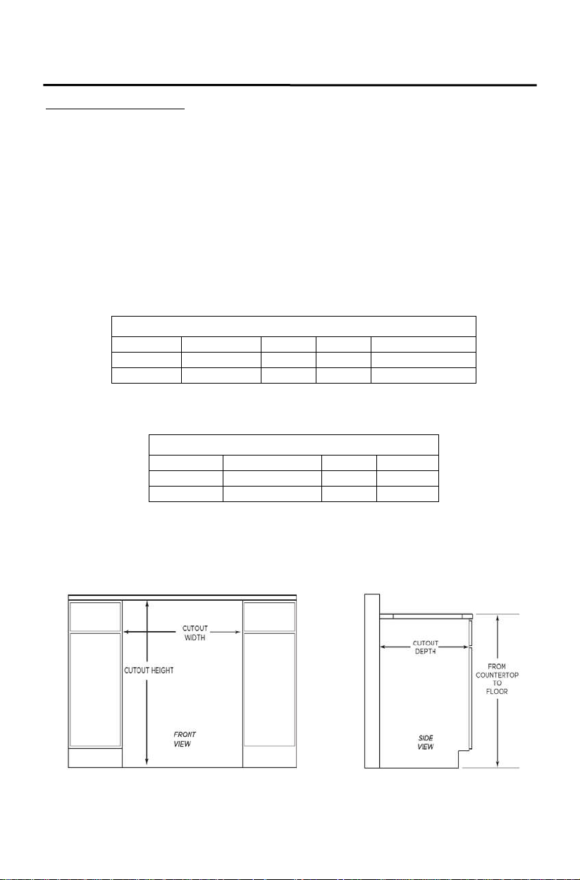
Product Dimensions represent the actual si ze of the appliance
Cutout Dimensions represent the opening dimensions needed for the appliance to fit into a built-in installation.
See diagrams below for reference.
Cutout Diagrams
Page 11
11
Installation Instructions (continued)
Attention
Never overload the cabinet.
Never open the door unless necessary.
Never cover shelves with aluminum foil or any other shelf material which may prevent air circulation.
Should the Azure applianc e be left empty for long periods, it is suggested that the appliance be unplugged,
and, after careful cleaning, leave the door ajar to allow air to circulate inside the cabinet in order to avoid
possible condensation, mold or odors from forming.
Electrical Connection
Check that the voltage marke d on the product corresponds with your supply voltage.
WARNING: Improper use of the grounded plug can result in the risk of electrical shock. If the power cord is
damaged, have it replaced by a qualified electrician or an author ized service center.
This appliance should be properly grounded for your safety. The powe r cord of this appliance is equipped with a
three-pin plug which ma tes with stan da rd three-pin wall outlets to minimize the possibility of electrical shock.
Never under any circumstances cut or remove the third ground prong from the power cord supplied. For persona l
safety, this appliance must be properly grounded.
This appliance requires a standard 115/120 Volt AC~60Hz electrical ground outlet with three pins. Have the
wall outlet and circuit ch ecked by a qualified electrician to make sure the outlet is properly grounded. When a
standard two-pin wall outlet is encountered, it is your responsibility and obligation to have it rep laced with a
properly grounded three-pin wall outlet.
To prevent accidental injury, the cord should be secured behind the appliance and not left exposed or dangling.
The appliance should alwa ys be plugged into its own individual electrical outlet which has a voltage rating that
matches the rating labe l on the appliance. This provides the best performance and also prevent overloading
wiring circuits that could cause a fire hazard from overheating. Never unplug the appliance by pulling the power
cord. Always grip the plug firmly and pull straight out from the receptacle. Repair or replace immediately all
power cords that have become frayed or otherwise damaged. Never use a cord that shows cracks or abrasion
damage along its length or at either end. When moving the appliance, be car e f ul not to damag e t he po w e r cord.
Electrical fuse prote ction of at least 10 amperes must be provided . If the socket is no longer accessible once the
appliance has been built-in, suitable measures must be taken during electrical installation to ensure that the
appliance can be disconnected from the electrical so cket when needed.
Never use your appliance with an extension cord unless this cord has been checked and tested by a qualified
technician or service person. The extension cord must be a UL/CUL Listed, 3-wire grounding extension cord
that has a grounding plug and outlet and that the electrical rating of the cord is 115 volts and at least 10 amper es.
Page 12
12
Installation Instructions (continued)
Installing the Handle
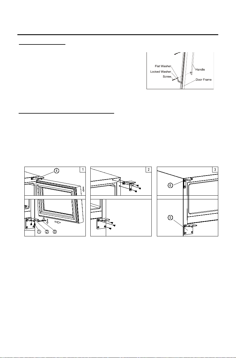
1. Remove the door gasket on the side you wish to install the
handle. Under the gasket you will see two de signated
holes for handle installa tion
2. Install the handle ti ghtly as shown above with two screws,
lock washers and flat washe rs provided.
3. Replace the door gasket.
Reversing the door swing of your applia nc e
Should you desire to reverse the opening direction of the door, please follow the instructions below:
Note: Al l parts remove d mu st be saved to do the reinstallation of door
1. Lock screws
2. Right lower hinge
3. Door shaft assembly
4. Right top hi ng e
1. Open the glass door and remove the two screws, under the right bottom corner of the door, that are used to
hold the right lower hinge to the door shaft assembly. Be careful to support the door with both hands to
prevent it dropping after removing the screws. (Figure 1)
2. Pull down to remove the door and place it on a padded surface to prevent scratching it. (Figure 1)
3. Remove the right top hinge and right lower hinge. (Figure. 3). Take the left top hinge and left lower hinge
from the plastic bag tha t in c l udes the instruction man ua l then install them in the designated positions on the
left side of cabinet. (Figure 4)
4. Turn the glass door around 180º and then relocate the door to the designate d position.
5. Glass door
6. Cabinet
7. Left top hinge
8. Left lower door hinge
5. Then screw the bottom hing e assembly on the left designated posit ion and tigh ten it after the door is level ed.
(Figure 6)
6. Reassemble the ventila tion grills.
Page 13
13
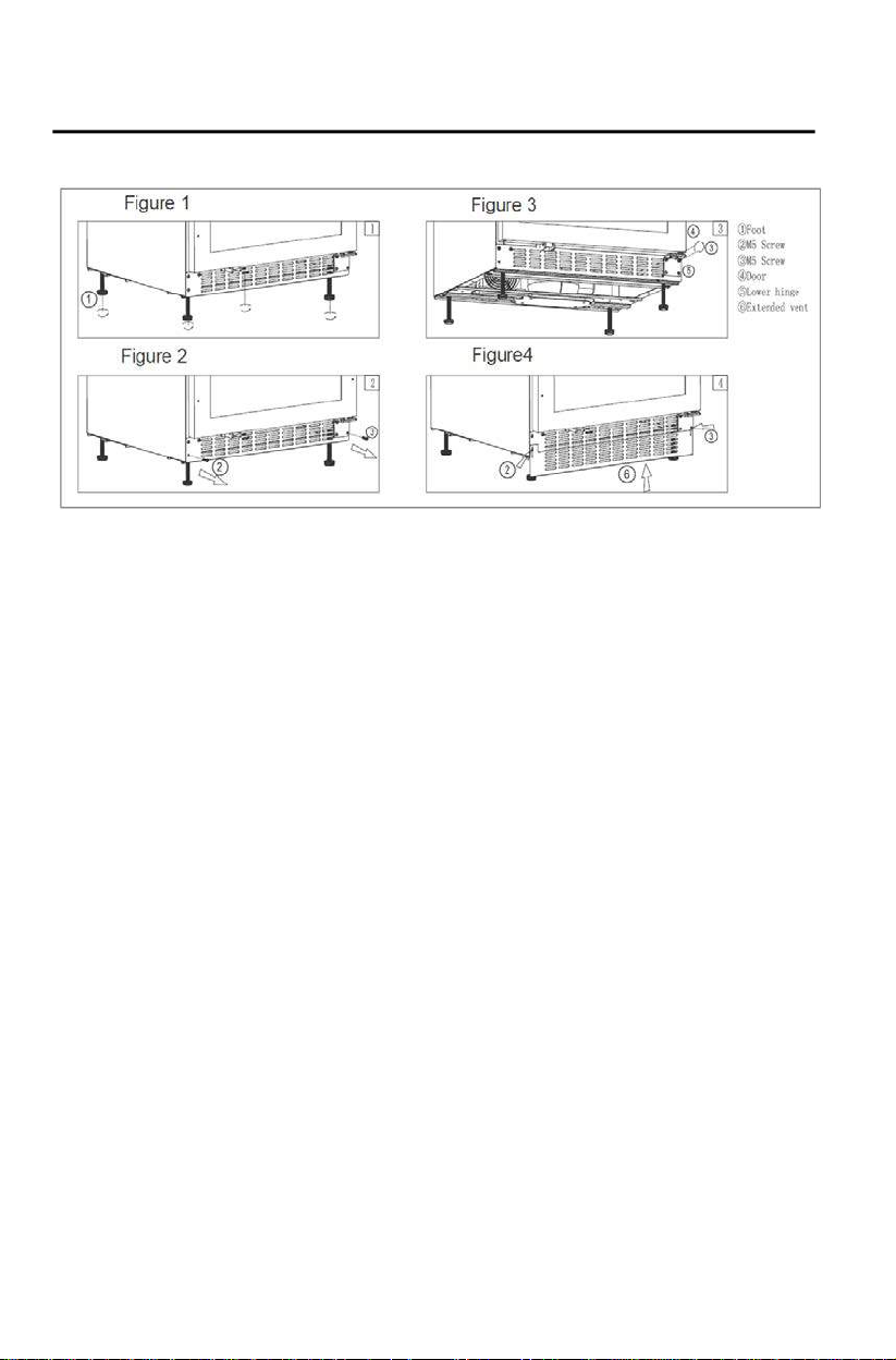
How to Install a nd Adjust the Botto m Ve nt
Figure 1: The legs come packaged at their lowest height of 32.5”. You can extend these legs up to 34.5” (or your
desired height) by unscrewing them counterclockwise.
Figure 2: Using a Philips screwdriver, remove screw #2 and bolt #3.
Figure 3: Loosen the remaining two screws on the top of the door bracket and make sure there is now a gap be tween
the door bracket and existing vent (#5).
Figure 4: Install the additional/extended vent (#6) from the bottom, sliding it into the gap created in Figure 3 on the
right side of the cabinet and to the front of the existing left side vent. Set the height as you desire and then re-install
and tighten down all bolts.
Page 14
14
How to Install an Overlay Panel
Only for Model Numbers:
A115WC-O; A124WC-O; A115BEV-O; A124BEV-O; A115R-O; A124R-O
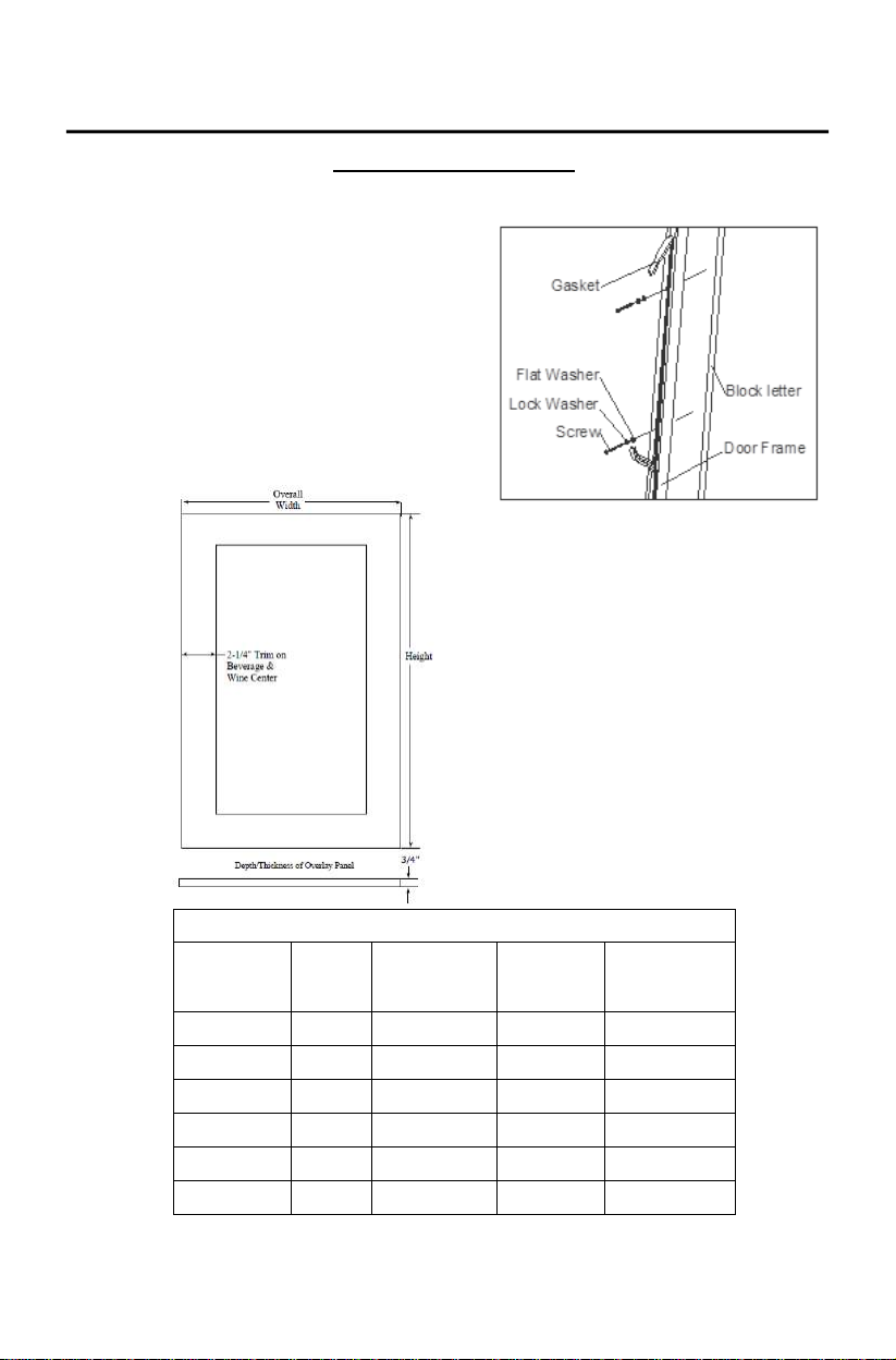
1. Remove the door gasket from th e interior of the door.
2. The screws that come with the unit are intended to be
used with a ¾” front panel.
3. Clamp your front panels to the frame of the door and
then anchor the panel to the door, using the screw, lock
washer and flat washer provided for each mounting hole.
4.
Re-install the gasket into the door assembly.
Dimensions for Overlay Panels
Model Height
A115WC-O 23-3/8” 14-1/2” 2-1/4" 3/4"
A124WC-O 28-1/8” 23-1/8” 2-1/4" 3/4"
A115BEV-O 23-3/8” 14-1/2” 2-1/4" 3/4"
A124BEV-O 28-1/8” 23-1/8” 2-1/4" 3/4"
A115R-O 23-3/8” 14-1/2” N/A 3/4"
A124R-O 28-1/8” 23-1/8” N/A 3/4"
Total Width
of Door
Width of
Trim
Depth /
Thickness of
Trim
Page 15
15
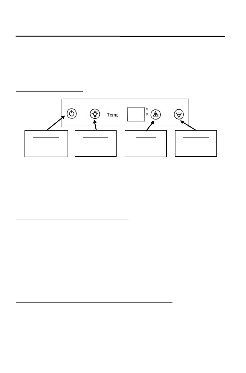
Power Button
Light Button
Up Button
by 1°C or 1ºF
Down Button
by 1°C or 1ºF
Operating Your Azure Appliance
When you use your Azure appliance for the first time, or restart the appliance after having been shut off for a
long period of time, there could be a few degrees variance between the temp erature you select and the one
indicated on the LED readout. This is normal and is due to the length of time that it was ina ctive. Once the
appliance has been running for a few hours, the temperature readout will go back to normal.
If the unit is unplugged, power lost, or turned off, you must wait 3 to 5 minutes before restarting the unit. If you
attempt to restart before this time delay, the appliance may not start and will kee p the last set temperature.
The Controls of Azure Appliance
To turn the
appliance on or off
To turn the inner
light on or off
Use to raise an d
set tempera t ur e
Use to lower and
set tempera t ur e
ºF/ºC Selector
Y ou ca n choose to display temperatures in Celsius or Fahrenheit. To change the temperature from Fahrenheit to Celsius
or from Celsius to Fahrenhe it, touch and hold the button for 5 seconds .
Setting a Temperature
The temperature will increase by 1ºC or 1ºF if you touch the UP mark once, and will decreas e 1ºC or 1ºF if
you touch the DOWN mark once.
Setting the Temperature Control for your Wine Center
Model Numbers: A115WC-S; A115WC-O; A124WC-S; A124WC-O
• Your wine cellar has one temperature controlled compartment, which has a temperature range
between 40° and 64°F (5 and 18°C).
• It is recommended to set the temperature between 55-64°F (12°C to + 18°C) range for storing red
wines and to adjust the temperature between 40-55°F range (5° and 12°C) for champagnes and
white wines.
• The Wine Center should be placed in a position where the ambient temperature is between 60-
95ºF (16-35°C). If the ambi ent temperature is above or below this ran ge, the performance of the
unit may be affected.
o For example, placing your unit in extreme cold or hot conditions may cause interior
temperatures to fluctuate. The range of 40-65ºF (5-18°C) for a wine center may not be
reached.
Setting the Temperature Control for your Beverage Center and Refrigerator
Model Numbers: A115BEV-S; A115BEV-O; A115R-S; A115R-O; A124BEV-S; A124BEV-O; A124R-S; A124R-O
• Your refrigerator and/or beverage center has one temperature controlled compartment, which has a
temperature range between 34° and 43° F (1 and 6°C).
• The refrigerator and /or beverage center should be plac e d in a po s ition where the ambient
temperature is between 60-95ºF (16-35°C). If the ambient temperature is above or below this
range, the performance of the unit may be affected.
o For example, placing your unit in extreme cold or hot conditions may cause interior
temperatures to fluctu ate. The range of 34° and 43° F (1 and 6°C) may not be reached.
Page 16
16
Operating Your Azure Appliance (continued)
Key Lock
If in 2 minutes without touching any key, the controls will be locked automatically. To release the lock, touch the up
and down marks at the sa me t im e for at least 5 sec onds.
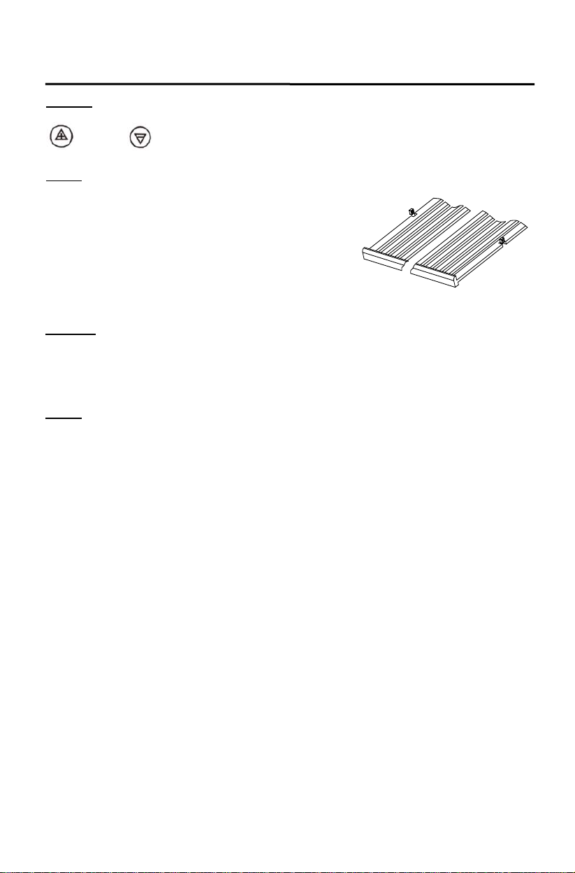
Shelves
• To prevent damaging the door or door gasket, make sure
the door is fully open when pu lling shelves out of the rail
compartment.
• The shelves are designed with an emergency stop to
prevent them being removed too far when loaded. For easy
access to the bottles stored, pull the shelves o ut
approximately a third of the way.
• To remove the shelves, simply pull the shelf forward to the
Defrosting
Storage
“stopper” then lift the entire grate up and over the stopper.
• The unit defrosts automatically.
• The evaporator behind th e rear wall of the unit defrosts automatica lly. The condensate collects in the
drainage channel behind the rear wall of the unit, and flows through the drainage hole into the drip
tray by the compressor where it evapora
• Many bottles may differ in size and dimensions. As such the actual number of bottles you may be
able to store may vary.
tes.
Page 17
17
Care and Maintenance
Cleaning Your Azure Appliance
• Turn off the power, unplug the appliance, and remove all items includ ing shelves and rack.
• Wash the inside surfaces with a warm water and baking soda solution. The solution should be about 2
tablespoons of baking soda to a pint of water.
• Wash the shelves with a mild deterge n t s olution.
• Wring excess water out of the sponge or cloth when cleaning any area of the contr ols.
• Wash the outside cabinet with warm water and mild liquid detergent. Rinse well and wipe dry with a
clean soft cloth.
Power Fail ure
• Most power failures are c orrected within a few hours and should not affect the temperature of your
appliance if you minimize the number of times the door is opened. If the power is going to be off for a
Vacation Time
Moving Your Wine Center
Energy Saving Tips
longer period of time, you need to take the proper steps to protect your contents.
• Short holidays: Leave the appliance in operation for holidays of less than three weeks.
• Long absences: If the appliance will not be used for several months, r emove all items, turn off the
appliance and unplug. Clean and dry the interior thoroughly.
o To prevent odor and mold growth, leave the do or open slightly, blocking it open if
necessary.
• Remove all items.
• Securely tape down all loose items (shelves) inside your appliance.
• Turn the adjustable leg a ll the way up (clockwise) to the base to avoid damage.
• Tape the door shut.
• Be sure the ap pl iance stay s se c u re in the upright position during transportation. Also protect outside of
appliance with a blanket , or similar item.
• The appliance should be located in the cooles t area of the room, away from heat producing appliances,
and out of the direct sunlight.
• Ensure that the unit is adequately ventilated. Never cover air vents.
• Only open the door for as long as necessary.
Page 18
18
Troubles ho ot ing Guide
POSSIBLE PROBLEM POSSIBLE CAUSE
• Not plugged in.
The circuit breaker tripped or a blown fuse.
The door gasket does not seal properly.
The room temperature is hotter than normal.
not seal properly.
Not plugged in.
• The light switch is “OFF.”
Vibrations.
Check to assure that the Wine Center is level.
• The Wine Center is not level.
• The shelves are out of position.
Display “EL” or “EH”.
• The air temperature sensor is failed. Contact Customer Support
Wine Center does not operate.
Wine Center is not cold enough.
Turns on and off frequently.
The light does not work.
The Wine Center seems to
make too much noise.
The door will not close properly.
• The applianc e is turned off.
•
• Check the temperature control setting.
• External en vironment may require a higher setting.
• The door is opened too often.
• The door is not closed completely.
•
•
• A large amount of contents has been added to the Wine Center.
• The door is open too often.
• The door is not closed completely.
• The temperature control is not set correctly. The door gasket does
•
• The circuit breaker tripped or a blown fuse.
•
• The rattling noise may come from the flow of the
refrigerant, which is normal. As each cycle ends, you
may hear gurgling sounds caused by the flow of
refrigerant in your Wine Center.
• Contraction and expansion of the inside walls may
cause popping and cracking noises.
• The Wine Center is not level.
• The door was reversed and not properly installed.
• The gasket is dirty.
Page 19
19
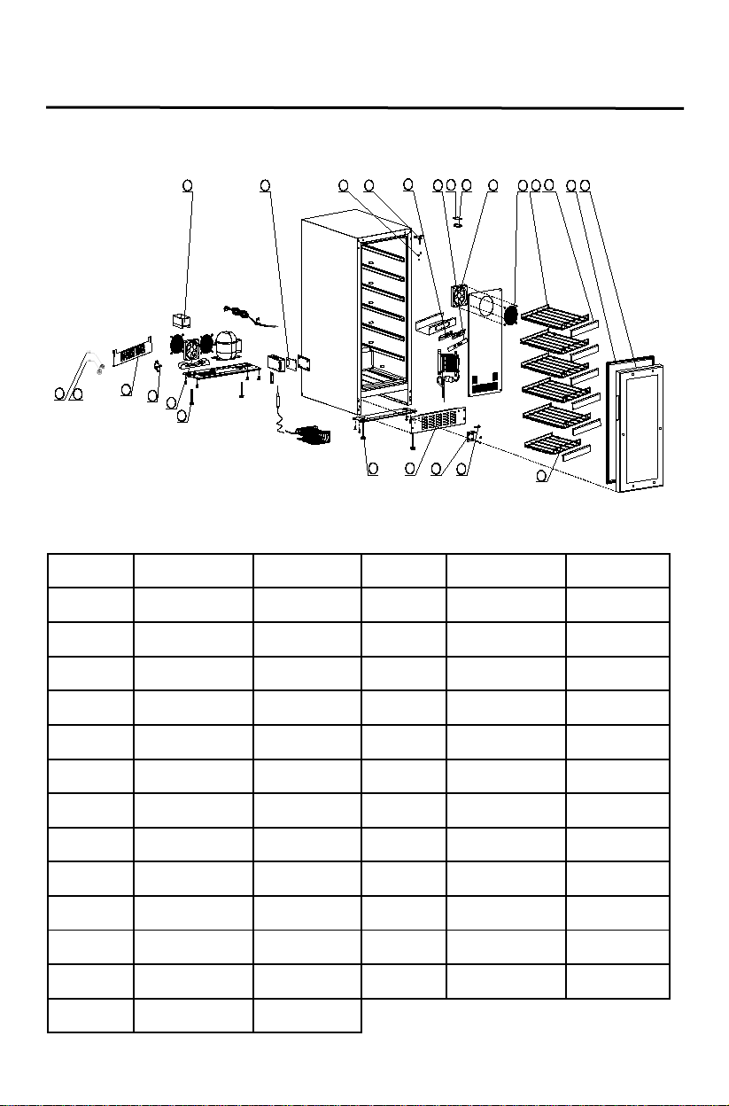
Parts List ing
Temperature
control sticker
Compressor
starter
Compressor
protector
1
Temp.
c
F
2
3
4
5
6
7
8
9
10
11
12
13
14
15
16
17
18
19
20
21
22
23
24
25
A115WC-O
Picture No. Description Part No. Picture No. Description Part No.
1 Out water tray 3.02.01.0264 14 Black door 3.02.09.1615
2 Power PCB 3.02.05.0459C 15 Small shelf 3.02.02.0818
3 Door plug 3.02.01.0216 16 Hinge fixed 3.02.02.0103B
4 Right upper hinge 3.02.02.0972A 17 Lower hinge 3.02.08.0966A
5 Display PCB 3.02.05.0463M 18 Vent 3.02.08.0822
6
3.02.03.A439 19 Front foot 3.02.01.0452
7 Light PCB 3.01.05.0072 20 Back foot 3.01.01.5446
8 Light PCB cover 3.01.01.0048A 21 Heating fan 3.02.05.0181
9 Cooling fan 3.02.05.0179A 22 Left upper hinge 3.02.02.0971A
10 Fan mask 3.02.02.0090 23 Extend vent 3.02.08.1828
11 Black shelf 3.02.02.0817 24
12 Wooden front 3.02.02.2150 25
13 Door seal 3.02.01.0305
3.02.06.0797
3.02.06.0796
Page 20
20
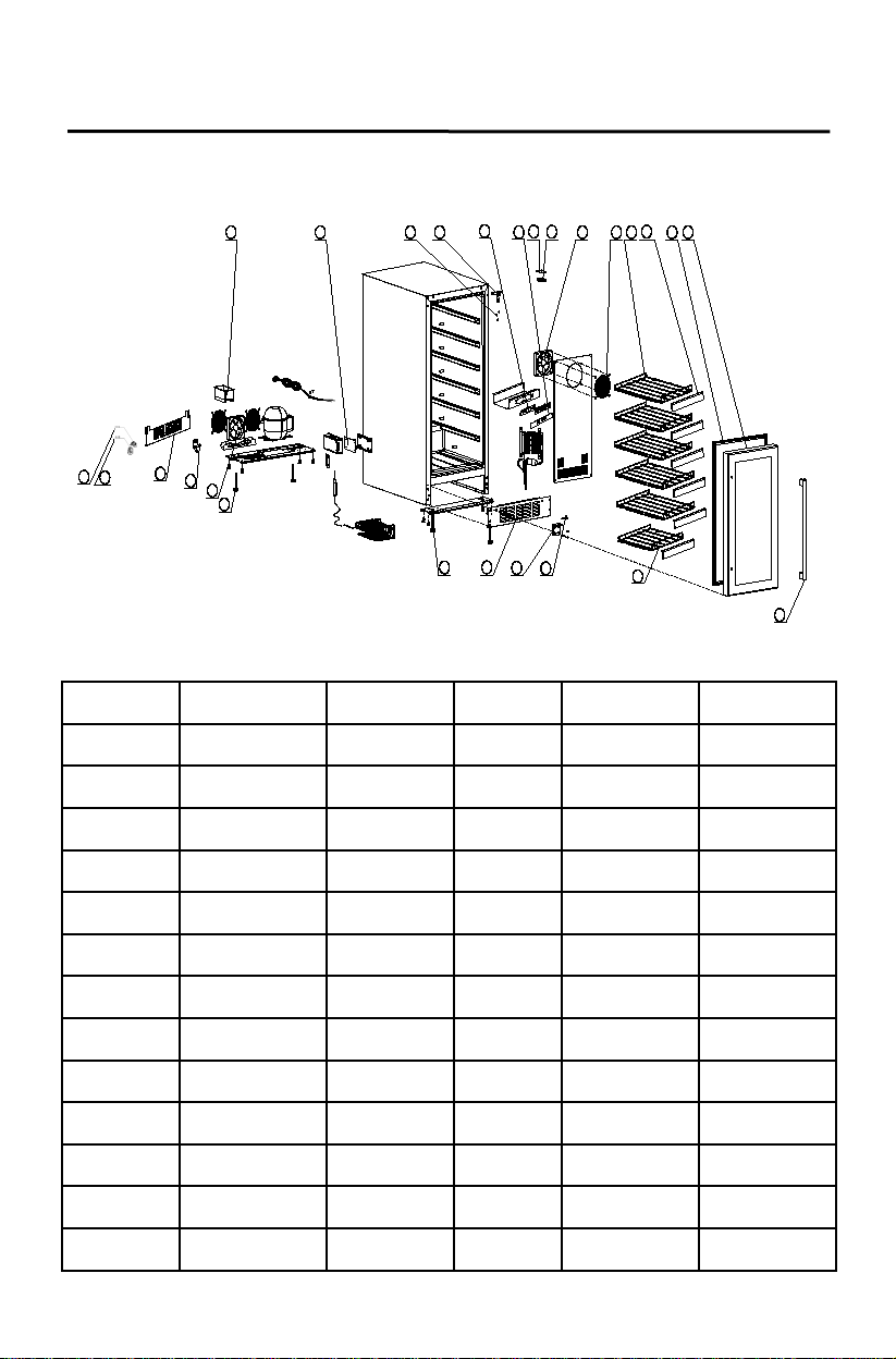
Parts List ing
Stainless steel
door
Temperature
control sticker
Compressor
starter
Compressor
protector
Stainless steel
door handle
21
1
2
5
6
7
9
10
11
12
17
19
18
3
8
16
15
4
13
14
Temp.
c
F
20
22
23
24
25
26
A115WC-S
Picture No. Description Part No. Picture No. Description Part No.
1 Out water tray 3.02.01.0264 14
2 Power PCB 3.02.05.0459C 15 Small shelf 3.02.02.0818
3 Door plug 3.02.01.0216 16 Hinge fixed 3.02.02.0103B
4 Right upper hinge 3.02.02.0397C 17 Lower hinge 3.02.08.0966A
5 Display PCB 3.02.05.0463M 18 Vent 3.02.08.0822
6
3.02.03.A439 19 Front foot 3.02.01.0452
7 Light PCB 3.01.05.0072 20 Back foot 3.01.01.5446
8 Light PCB cover 3.01.01.0048A 21 Heating fan 3.02.05.0181
9 Cooling fan 3.02.05.0179A 22 Left upper hinge 3.02.02.0379C
10 Fan mask 3.02.02.0090 23 Extend vent 3.02.08.1828
11 Black shelf 3.02.02.0817 24
12 Wooden front 3.02.02.2150 25
13 Door seal 3.02.01.0305 26
3.02.09.1616
3.02.06.0797
3.02.06.0796
3.02.02.0273A
Page 21
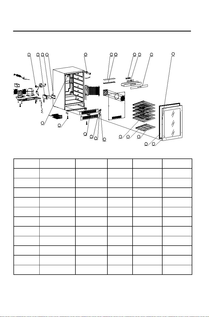
21
Parts List ing
Black glass
door
Small wire
shelf
Temperature
control sticker
Left upper
hinge
1 2 3 4
13
12
6 7 8 9
Temp.
c
10
15 14
5
F
16
22
11
17
20
21
18
19
A124WC-O
Picture No. Description Part No. Picture No. Description Part No.
1 Com pressor relays 3.02.06.0854 12
3.02.09.1617
2 PCB Box 3.02.01.1460A 13 Door seal 3.02.01.0319
3 Power PCB 3.02.05.0459C 14 Wooden front 3.02.02.1535
4 PCB box Cover 3.02.02.0972A 15
3.02.02.0798
5 Right upper hinge 3.02.08.1820 16 Big wire shelf 3.02.02.0797
6 Light PCB 3.02.05.0465 17 Hinge fixed 3.02.02.1849A
7 Light PCB cover 3.02.01.0864A 18 Lower hinge 3.02.08.0966B
8 Display PCB 3.02.05.0463M 19 Extend vent 3.02.08.1830
9 Display PCB fixed 3.02.01.0236A 20 Vent 3.02.08.1836
10
3.02.03.A238 21 Foot 3.02.01.0452
11 Recessed handle 3.01.08.0603 22
3.02.08.1823
Page 22
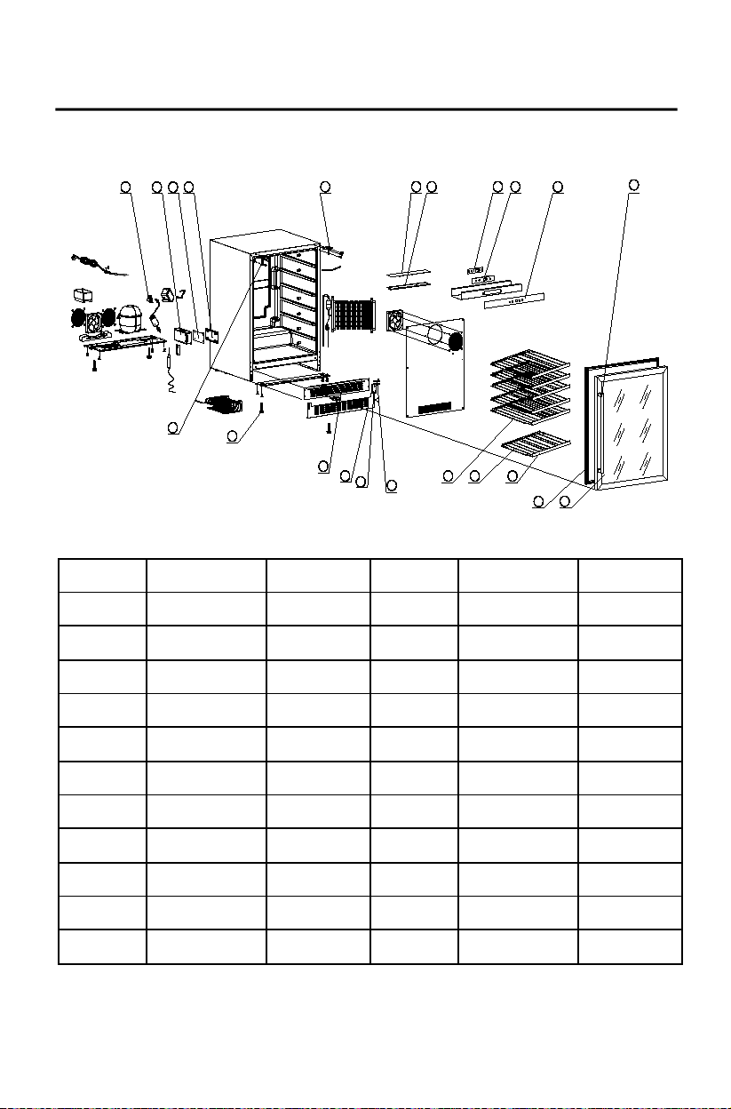
22
Parts List ing
Stainless steel
door
Temperature
control sticker
Stainless steel
handle
1 2 3 4
13
12
11
17
20
21
18
19
6 7 8 9
Temp.
c
10
15 14
5
F
16
22
A124WC-S
Picture No. Description Part No. Pictu re No. Description Part No.
1 Compressor relays 3.02.06.0854 12
2 PCB Box 3.02.01.1460A 13 Door sea l 3.02.01.0319
3 Power PCB 3.02.05.0459C 14 Wooden front 3.02.02.1535
4 PCB Box Cover 3.02.02.0972A 15 Small wire shelf 3.02.02.0798
5 Right upper hinge 3.02.02.0397C 16 Big wire shelf 3.02.02.0797
6 Light PCB 3.02.05.0465 17 Hinge fixed 3.02.02.1849A
7 Light PCB cover 3.02.01.0864A 18 Lower hinge 3.02.08.0966B
8 Display PCB 3.02.05.0463M 19 Extend vent 3.02.08.1830
9 Display PCB fixed 3.02.01.0236A 20 Vent 3.02.08.1836
10
11
3.02.03.A238 21 Foot 3.02.01.0452
3.02.02.0273A 22 Left upper hinge 3.02.08.1823
3.02.09.1218
Page 23
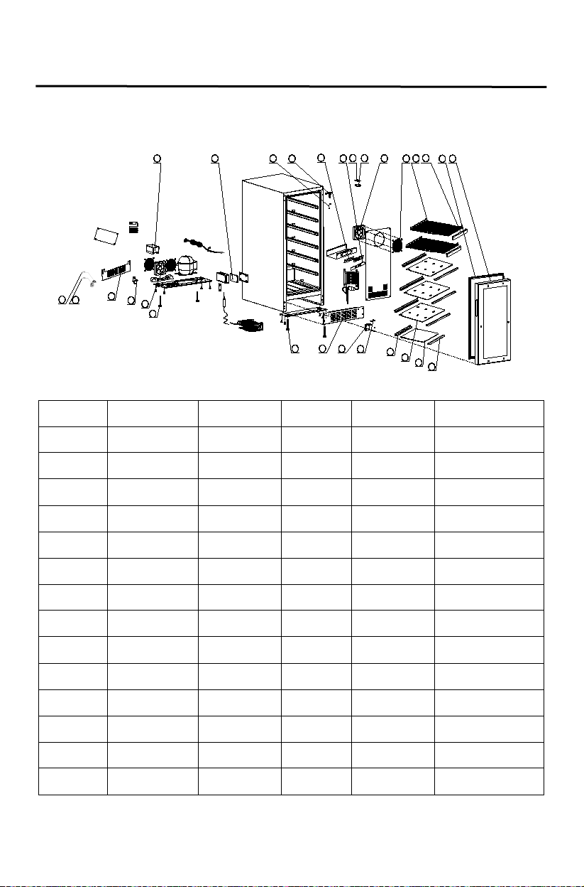
23
Shelf back
panel
Right upper
hinge
Temperature
control sticker
Left upper
hinge
Compressor
starter
Compressor
protector
Small Glass
shelf
Shelf front
panel
21
1
2
5
6
7
9
10
11
12
17
19
18
3
8
16
15
4
13
14
Temp.
c
F
20
22
23
24
25
26
27
28
Parts List ing
A115BEV-O
Picture No. Description Part No. Picture No. Description Part No.
1 Out water tray 3.02.01.0264 15
3.02.01.2169
2 Power PCB 3.02.05.0460C 16 Hinge fixed 3.02.02.0103B
3 Door plu g 3.02.01.0216 17 Lower hinge 3.02.08.0966A
4
3.02.02.0972A 18 Vent 3.02.08.0822
5 Display PCB 3.02.05.0569M 19 Front foot 3.02.01.0452
6
3.02.03.A439 20 Back foot 3.01.01.5446
7 Light PCB 3.01.05.0072 21 Heating fan 3.02.05.0181
8 Light PCB cover 3.01.01.0048A 22
9 Cooling fan 3.02.05.0179A 23 Extend vent 3.02.08.1828
10 Fan mask 3.02.02.0090 24
11 Black shelf 3.02.02.2218 25
3.02.02.0971A
3.02.06.0797
3.02.06.0796
12 Wooden front 3.02.02.2217 26 Big Glass shelf 3.02.09.1657
13 Door seal 3.02.01.0305 27
14 Black door 3.02.09.1615 28
3.02.09.1658
3.02.01.2168
Page 24
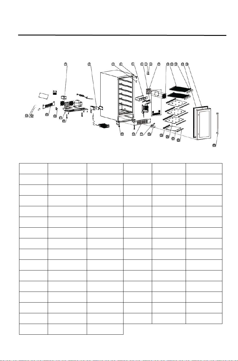
24
Parts List ing
Temperature
control sticker
Left upper
hinge
Compressor
starter
Compressor
protector
Small Glass
shelf
Shelf front
panel
Stainless steel
door
Stainless steel
door handle
A115BEV-S
Picture No. Description Part No. Picture No. Description Part No.
1 Out water tray 3.02.01.0264 16 Hinge fixed 3.02.02.0103B
2 Power PCB 3.02.05.0459C 17 Lower hinge 3.02.08.0966A
3 Door plug 3.02.01.0216 18 Vent 3.02.08.0822
4 Right upper hinge 3.02.02.0397C 19 Front foot 3.02.01.0452
5 Display PCB 3.02.05.0463M 20 Back foot 3.01.01.5446
6
7 Light PCB 3.01.05.0072 22
8 Light PCB cover 3.01.01.0048A 23 Extend vent 3.02.08.1828
9 Cooling fan 3.02.05.0179A 24
10 Fan mask 3.02.02.0090 25
11 Black shelf 3.02.02.0817 26 Big Glass shelf 3.02.09.1657
12 Wooden front 3.02.02.2150 27
13 Door seal 3.02.01.0305 28
14
3.02.03.A439 21 Heating fan 3.02.05.0181
3.02.02.0379C
3.02.06.0797
3.02.06.0796
3.02.09.1658
3.02.01.2168
3.02.09.1616 29
3.02.02.0273A
15 Shelf back pane l 3.02.01.2169
Page 25
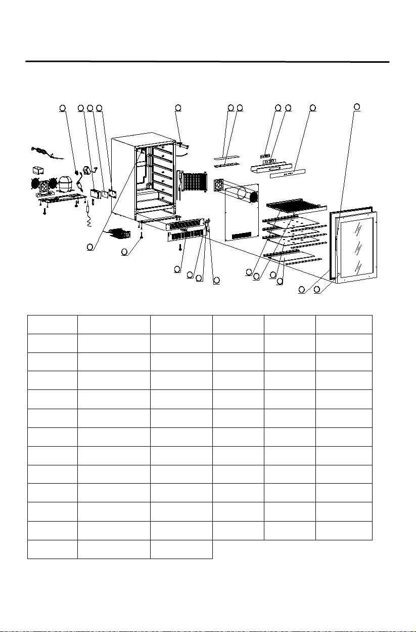
25
Small glass
shelf
Big glass
shelf
Wooden
front
Black wire
shelf
Temperature
control sticker
Left upper
hinge
1 2 3 4
6 7 8 9
Temp.
c
10 5
F
23
13
12
15
14
17
16
11
18
21
22
19
20
Parts List ing
A124BEV-O
Picture No. Description Part No. Picture No. Description Par t No.
1 Comp ressor relays 3.02.06.0854 13 Door seal 3.02.01.0319
2 PCB Box 3.02.01.1460A 14
3 Power PCB 3.02.05.0459C 15
4 PCB box Cover 3.02.02.0972A 16
5 Right upper hinge 3.02.08.1820 17
6 Light PCB 3.02.05.0465 18 Hinge fixed 3.02.02.1849A
7 Light PCB cover 3.02.01.0864A 19 Lower hinge 3.02.08.0966B
8 Display PCB 3.02.05.1020 20 Ext end vent 3.02.08.1830
9 Display PCB fixed 3.02.01.0236A 21 Vent 3.02.08.1836
10
11 Recessed handle 3.01.08.0603 23
12 Black glass door 3.02.09.1617
3.02.09.1697
3.02.09.1696
3.02.02.1535
3.02.02.0797
3.02.03.A238 22 Foot 3.02.01.0452
3.02.08.1823
Page 26
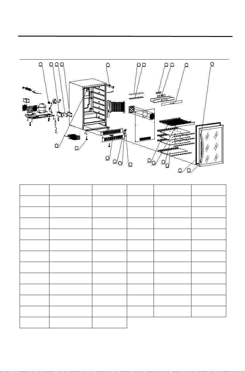
26
Parts List ing
Picture
No.
Temperature
control sticker
Stainless steel
handle
1 2 3
4
11
18
21
22
19
20
6
7
8 9
Temp.
c
10
5
F
23
13
12
15
14
17
16
Picture No. Description Pa rt No.
A124BEV-S
Description Part No.
1 Compressor relays 3.02.06.0854 13 Door se al 3.02.01.0319
2 PCB Box 3.02.01.1460A 14 Small glass shelf 3.02.09.1697
3 Power PCB 3.02.05.0459C 15 Big glass shelf 3.02.09.1696
4 PCB box Cover 3.02.02.0972A 16 Wooden front 3.02.02.1535
5 Right upper hinge 3.02.08.1820 17 Black wire shelf 3.02.02.0797
6 Light PCB 3.02.05.0465 18 Hinge fixed 3.02.02.1849A
7 Light PCB cover 3.02.01.0864A 19 Lower hinge 3.02.08.0966B
8 Display PCB 3.02.05.1020 20 Extend vent 3.02.08.1830
9 Disp lay PCB fixed 3.02.01.0236A 21 Vent 3.02.08.1836
10
11
3.02.03.A238 22 Foot 3.02.01.0452
3.02.02.0273A 23 Left upper hinge 3.02.08.1823
12 Stainless steel door 3.02.09.1218
Page 27
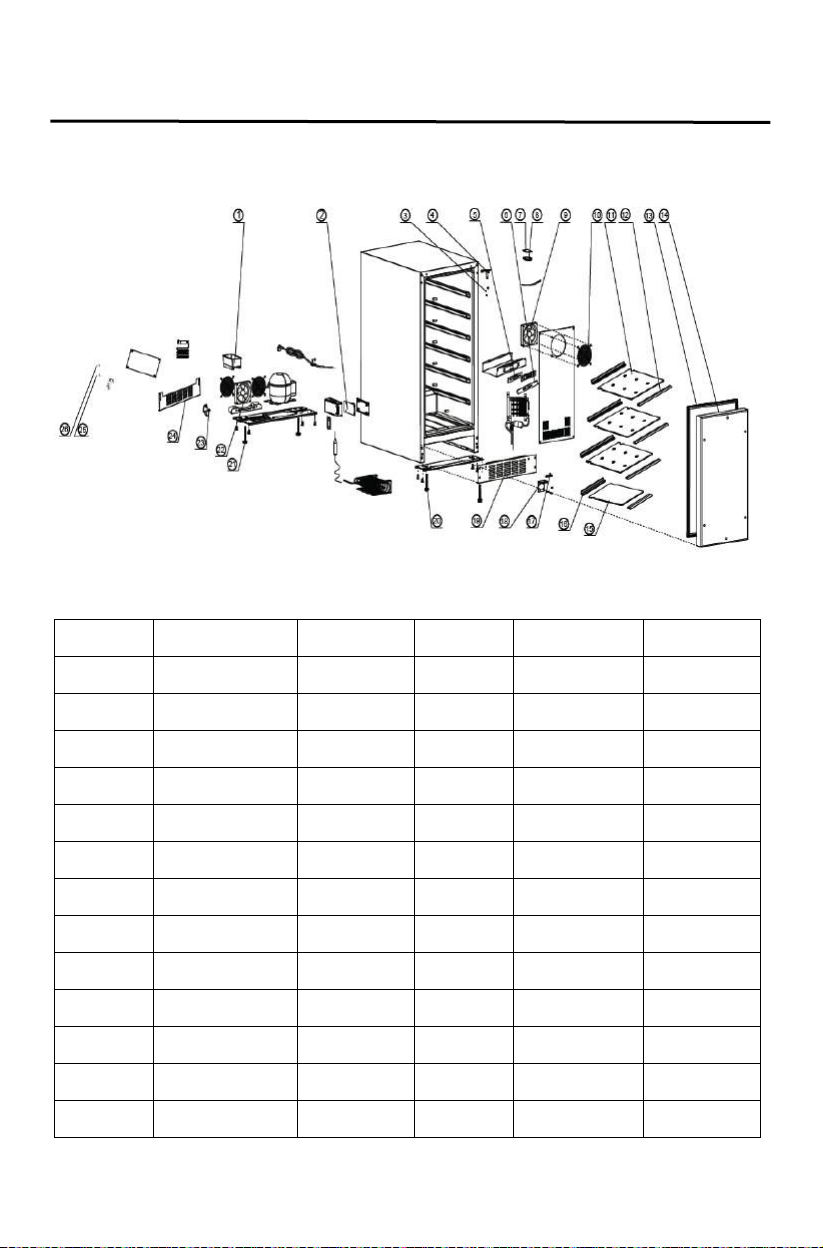
27
Parts List ing
Temperature
control sticker
Compressor
starter
Compressor
protector
A115R-O
Picture No. Description Part No. Picture No. Description Par t No.
1 Out water tray 3.02.01.0264 14 Black door 2.02.05.0382
2 Power PCB 3.02.05.0460C 15 Small Glass shelf 3.02.09.1658
3 Door plug 3.02.01.0216 16 Shelf back panel 3.02.01.2169
4 Right upper hinge 3.02.02.0972A 17 Hinge fixed 3.02.02.0103B
5 Display PCB 3.02.05.0569M 18 Lower hinge 3.02.08.0966A
6
7 Light PCB 3.01.05.0072 20 Front foot 3.02.01.0452
8 Light PCB cover 3.01.01.0048A 21 Back foot 3.01.01.5446
9 Cooling fan 3.02.05.0179A 22 Heating fan 3.02.05.0181
10 Fan mask 3.02.02.0090 23 Left upper hinge 3.02.02.0971A
11 Big Glass shelf 3.02.09.1657 24 Ext end vent 3.02.08.1828
12 Shelf front panel 3.02.01.2168 25
13 Door seal 3.02.01.0305 26
3.02.03.A439 19 Vent 3.02.08.0822
3.02.06.0797
3.02.06.0796
Page 28
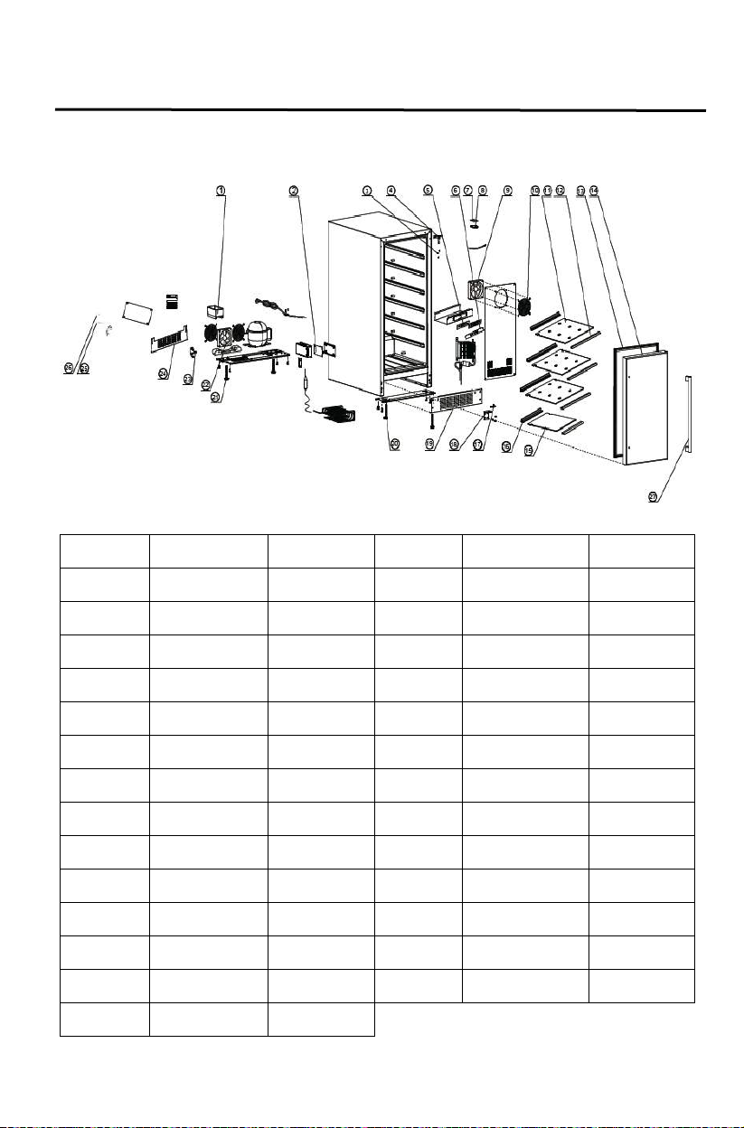
28
Temperature
control sticker
Compressor
protector
Stainless steel door
handle
Stainless steel
door
Parts List ing
A115R-S
Picture No. Description Part No. Picture No. Description Part No.
1 Out water tray 3.02.01.0264 15 Small Glass shelf 3.02.09.1658
2 Power PCB 3.02.05.0460C 16 Shelf back panel 3.02.01.2169
3 Door plug 3.02.01.0216 17 Hinge fixed 3.02.02.0103B
4 Right upper hinge 3.02.02.0972A 18 Lower hinge 3.02.08.0966A
5 Display PCB 3.02.05.0569M 19 Vent 3.02.08.0822
6
7 Light PCB 3.01.05.0072 21 Back foot 3.01.01.5446
8 Light PCB cover 3.01.01.0048A 22 Heating fan 3.02.05.0181
9 Cooling fan 3.02.05.0179A 23 Left upper hinge 3.02.02.0971A
10 Fan mask 3.02.02.0090 24 Ext end vent 3.02.08.1828
11 Big Glass shelf 3.02.09.1657 25 Compressor starter 3.02.06.0797
12 Shelf front panel 3.02.01.2168 26
13 Door seal 3.02.01.0305 27
14
3.02.03.A439 20 Front foot 3.02.01.0452
3.02.06.0796
3.02.02.0273A
2.02.05.0383
Page 29
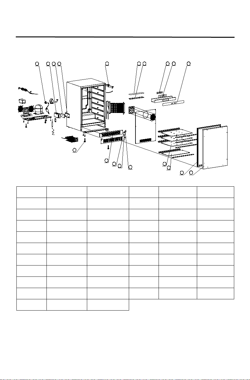
29
Compressor
relays
Display PCB
fixed
Temperature
control sticker
17
6 7 8 9
Temp.
c
10 5
F
12
11
14
13
15
18
19
16
1 2 3 4
Parts List ing
A124R-O
Picture No. Description Part No. Picture No. Description Part No.
1
2 PCB Box 3.02.01.1460A 12 Door sea l 3.02.01.0319
3 Power PCB 3.02.05.0459C 13 Small glass shelf 3.02.09.1697
4 PCB box Cover 3.02.02.0972A 14 Big glass shelf 3.02.09.1696
5 Right upper hinge 3.02.08.1820 15 Hinge fixed 3.02.02.1849A
6 Light PCB 3.02.05.0465 16 Lower hinge 3.02.08.0966B
7 Light PCB cover 3.02.01.0864A 17 Extend vent 3.02.08.1830
8 Display PCB 3.02.05.1020 18 Vent 3.02.08.1836
9
10
3.02.06.0854 11 Black door 2.02.05.0384
3.02.01.0236A 19 Foot 3.02.01.0452
3.02.03.A238
Page 30
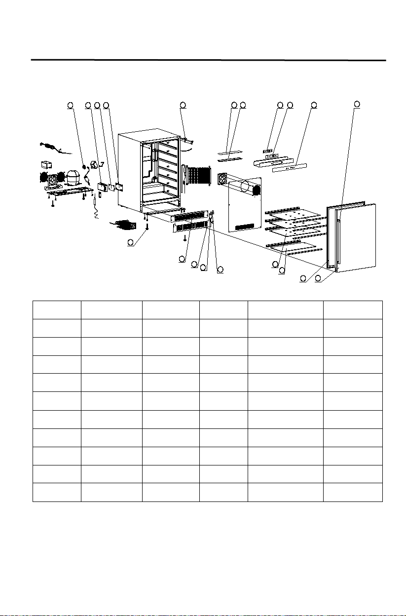
30
Compressor
relays
Right upper
hinge
Display PCB
fixed
Temperature
control sticker
6 7 8 9
Temp.
c
10 5
F
13
12
15
14
11
16
19
20
17
18
1 2 3 4
Parts List ing
A124R-S
Picture No. Description Part No. Picture No. Description Part No.
1
3.02.06.0854 11 Stainles s steel handle 3.02.02.0273A
2 PCB Box 3.02.01.1460A 12 Stainless steel door 2.02.05.0380
3 Power PCB 3.02.05.0459C 13 Door se al 3.02.01.0319
4 PCB box Cover 3.02.02.0972A 14 Small glass shelf 3.02.09.1697
5
3.02.08.1820 15 Big glass shelf 3.02.09.1696
6 Light PCB 3.02.05.0465 16 Hinge fixed 3.02.02.1849A
7 Light PCB c over 3.02.01.0864A 17 Lower hinge 3.02.08.0966B
8 Display PCB 3.02.05.1020 18 Extend vent 3.02.08.1830
9
10
3.02.01.0236A 19 Vent 3.02.08.1836
3.02.03.A238 20 Foot 3.02.01.0452
 Loading...