


Introduction
Congratulations! Now you are the owner of the most advanced state—of the—art VHF FM transceiver available today.
Please read this manual carefully before attempting to operate your PCS—6000 transceiver. This will ensure that you obtain the maximum operating convenience and versatility.
Unpack your PCS—6000 carefully and make sure that it is supplied with the standard accessories listed at page 14. Be sure to send in the warranty card. Notify the carrier immediately if there is any evidence of damage to the unit. Keep the
original packing materials in the unlikely event it becomes necessary to return the PCS—6000 for servicing.
CONT N NT S |
|
Cautions Before Operation |
2 |
Major Features |
3 |
Operating Controls and Functions |
4 |
How to use Keyboard |
6 |
How to Store Frequencies in Memory |
8 |
Recalling Memory Channels |
10 |
Memory Seining/Band Scanning |
11 |
Scanning Stop |
12 |
Priority |
12 |
Microphone |
13 |
Accessories List |
15 |
Specifications |
16 |

—1—
CAUTION BEFORE OPERATION -
1.Before connecting the unit to a power supply, make sure that you have the polarity correct. The red lead of the
2.power cord should go to the positive (+) terminal of the power supply or battery.
In mobile installations, the system must normally ~e negative—ground. That is, the negative terminal of the battery should be connected to the automobile chassis. Host modern cars and trucks are negatively grounded, but a few use positive grounding. In this case, the 005—6000 and antenna must ~e insulated from the vehicle chassis or a short circuit will occur.
3.The rated supply voltage of this unit is 13.8VDC ± 151. So, be sure that the power supply voltage is 12 to 14
4.volts. Voltages less than ll.7VOC or greater than l5.9VDC will cause improper operation and possible damage
5.to the unit .
3.Be sure that the antenna is securely mounted on your car and also check the external antenna system for
4.short —circuit using an ohmmeter and then, firmly screw the antenna plug into the antenna connector 00 the
5.rear panel of the unit, ho sure to use a 50—ohm impedance cable.
4.Be sure that the unit is properly located.
When installing it, be sure that it is not placed in a location where it will be exposed to direct sunlight for
prolonged
periods. Also keep the unit wail away from heater outlets.
After parking for long periods in hot weather, the P05—6000 should not be used for transmitting until the vehicle
interior has cooled down.
-2 –

MAJOR FEATURES
1. C—MOS Microcomputer Control
The built—in microcomputer employs the latest in CMOS technology, to provide you with unprecedented operating features. This microcomputer controls all of the scanning, channel selection, offset frequencies ,sub—audible tone operation and display functions. The lithium battery ensures that microcomputer information is stored even when power is removed.
2. Unprecedented Wide Frequency Coverage
The PCS—6000 receives 118.000 to 173.995MHz aircraft AM and FM and transmits 140.100 to 149.995MHz. Modifiable to all MARS and CAP frequencies (Proof of
authorization/license required)
3. AM Air Band Receiver Capability
The unit receives the AM band of 118.000 to 135.99Mhz.
4. 20—Channel Memory in The unit receives AM band of 118.000 to 135.995MHz.
Two Banks plus 1 Temporary Channel
Two memory banks, A and B have 10 memory channels each. The memories store frequency, shift width, offset information, and sub—audible tone frequency as programmed. An extra memory channel (that we call TM — Temporary Memory) is provided to allow you to store
any operating condition right at once.
5. Versatile Scanning Functions
Dual memory scan, programmable band scanning , hold scan and delay scan functions are provided. The operations are detailed in the keyboard operation.
6. Priority Channel Monitoring
Memory channel AD (the first channel in memory bank A) is monitored at every four seconds regardless of any operating condition. When a signal is received, a beep will be heard twice.
7. Programmable Frequency Steps
In memory, frequency steps can be set at 5kHz to 20kHz increments of 5kHz. (European version programmable at 12.5kHz to 50kHz in increments of 12.5kHz.)
8. Built—in Programmable Tone Encoder
57 different tones are built in and tone frequencies can be programmed into each memory channel.
9. Feather—touch Tuning Control Keyboard
The LED back lighted light touch keyboard performs all tuning operations simply by pushing the key(s) and key actuation is audibly verified.
10. Large LCD (Liquid Crystal Display)
The LCD shows the operating frequency, S/RF , memory channel in use and various other operating functions. The LCD is back—lighted by green LEDs, making it possible for you to read the display even in total darkness.
11. Azden Traditional Discriminator Scan Centering
—3—
-OPERATING CONTROLS AND FUNCTIONS –
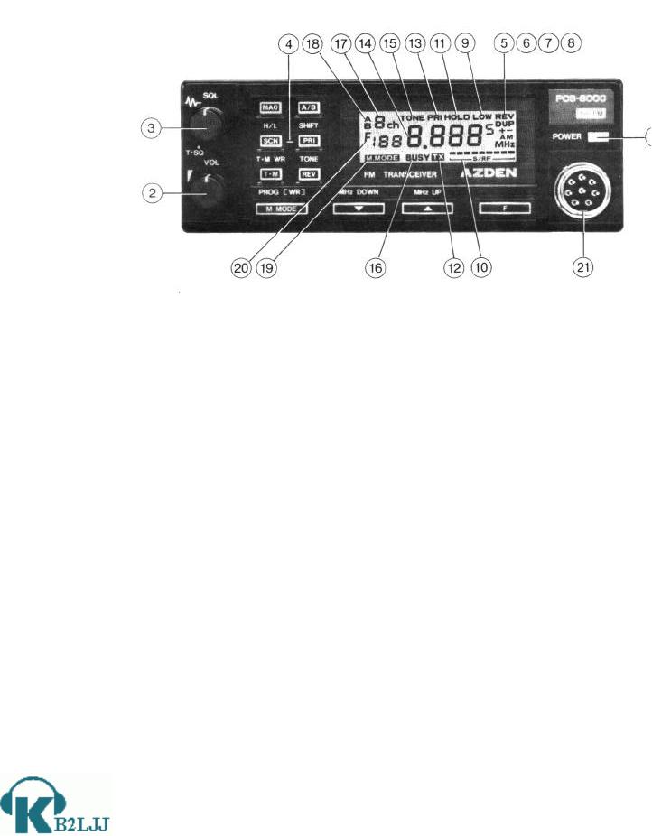
(1)Power Switch: Push ‘ON’ Push ‘OFF’ switch. Pressing the button once will turn the power ON and pressing it again will turn the power off.
(2)Volume Control: Turning the knob clockwise will increase the sound volume.
(3)Tone Squelch (TSQ)/Squelch Control. This control is used to eliminate annoying background noise when no signal is present. To adjust the control properly for reception, first turn the knob counterclockwise until background noise is heard. Then rotate it slowly clockwise until background just disappears. Leave the knob at this position for normal use. If the squelch control is turned further clockwise, stronger signals will be required to open the squelch and allow reception.
When the knob is set to the “T.SQ” position, the squelch will open only for signals that accompany a certain designated sub audible tone frequency. (An optional tone squelch unit is required)
(4)Keyboard Switches: The keyboard switches are used to select various operation modes programmed inside the microcomputer. All the keys are LED illuminated for easy location in darkness. Refer to ‘Details of Keyboard” for each key operation and function.
(5)Minus (—) Shift Indicator: When the indicator is lit, transmission occurs at a frequency below the receiving frequency, according to the preset value of shift.
(6)Plus (+) Shift Indicator: When the indicator (+) is lit, transmission occurs at a frequency above the receiving frequency, according to the preset value of shift.
(7)Duplex (“DUP”) Indicator: When the indicator (DUP) is lit in calling memory channel, it means that the receiving frequency and transmitting frequency is differently set up from each other.
—4----

(8)Reverse Mode Indicator (REV): This indicator is lit when the reverse operation mode is in use. (See: Reverse mode operation Page 7)
(9)Low Power Indicator (LOW): When the transmitter output is set at low power (5W— PCS—6000/IOW—PCS—6000H), this indicator comes on. In the high power mode (25W
— PCS60OO/45W — PCS—6000H), this indicator is not lit.
(10)Signal Indicator (S/RE): This indicator shows the relative incoming signal strength in the receive mode, and the relative transmitter output power in the transmit mode. (Note: Even in high power transmit mode, it is possible that not all of the indicators will come on. This may happen if the antenna SWR is high.)
(11)Hold Indicator (HOLD): This indicator tells you that scanning is in the HOLD mode. In this scan mode, scanning will stop at any occupied channel and will resume in either about 3 seconds or 6 seconds after the signal disappears. If the~ HOLD scan is not lit, the unit is in the DELAY scan mode. In this mode, scanning will stop at any occupied channel and then resume after 6 seconds irrespective of signal condition. For the HOLD mode and DELAY mode switchover, refer to “How To Program
(12)Transmit Indicator (TX): This indicator lights up when the PTT switch is depressed, indicating that the unit is in the transmit mode.
(13)Priority Indicator (PRI): This indicator lights up to tell you that the unit is in the priority mode. (See Priority at page 12
(14)Frequency Indicator
(15)Tone Indicator (TONE): This indicator lights up to tell you that either tone encoder or tone decoder i5 activated for use with an optional tone decoder when built in or both tone encoder and decoder are made activated. More specifically, see the table below as regards the ‘TONE’ indicator vs. tone encoder/decoder, keyboard tone switch and tone squelch switch.
TONE |
|
‘TONE’ Indicator |
|
Encoder |
Decoder |
Tone Switch |
T.SQ Switch |
x |
x |
x |
x |
x |
o |
x |
x |
o |
x |
o |
x |
o |
o |
o |
o |
o: pro—programmed—in |
|
o=Switch ‘On’ |
|
(16)Busy Indicator (BUSY): This indicator lights up when the unit is receiving signals over squelch threshold level, indicating that a channel is in use.
(17)Memory Address Indicator: This unit has two memory banks, A and B, each of which has ten (l0) memories, indicating the memory address in use by 0ch to 9ch.
(18)Memory Bank Indicator: When memory bank A is selected, this indicator shows A and when bank B is selected, this indicates B. When both A and B are indicated, the blinking bank is selected, connecting A and B banks in series and enabling you to call 20 channel frequencies continuously and or scan 20 channels.
—5—
 Loading...