

Page 1

Rev. 1.5 September 2017
Page 2

Contents
Notices .................................................................................................................................................................. 7
Trademark Acknowledgments .......................................................................................................................... 7
FCC Notice ........................................................................................................................................................ 7
Compliance Information ................................................................................................................................... 7
Glossary ................................................................................................................................................................ 8
Introduction .......................................................................................................................................................... 9
Scope ................................................................................................................................................................ 9
Related Documentation ................................................................................................................................... 9
Product Overview ............................................................................................................................................... 10
Wavelet Kits .................................................................................................................................................... 11
Wavelet Device ............................................................................................................................................... 11
Sensor Integration .......................................................................................................................................... 11
User Interface ................................................................................................................................................. 12
Installing the Wavelet Kit ................................................................................................................................... 13
Assembling the Wavelet Kit............................................................................................................................ 13
Connecting to an External Power Source ....................................................................................................... 13
Turning the Wavelet On ................................................................................................................................. 14
Ayyeka Web-based Data Management System ................................................................................................. 15
Accessing the Data Management System ...................................................................................................... 15
Understanding Sites’ Hierarchy ...................................................................................................................... 15
Understanding User Roles .............................................................................................................................. 17
Account roles .............................................................................................................................................. 17
Organization roles ...................................................................................................................................... 17
Getting Started ............................................................................................................................................... 17
Using the Ayyeka Visualization window ............................................................................................................. 19
Viewing Site Information ................................................................................................................................ 21
Understanding the Data Stream Chart ........................................................................................................... 23
Setting the Time Range............................................................................................................................... 23
Setting the Time Frame .............................................................................................................................. 23
Using the Zoom and View tools .................................................................................................................. 24
Comparing Data Streams ................................................................................................................................ 24
Page 3

Generating Reports ............................................................................................................................................ 26
Stream History Report .................................................................................................................................... 26
Aggregation Report ........................................................................................................................................ 28
Custom Stream History Report ...................................................................................................................... 31
Managing Sites ................................................................................................................................................... 34
Viewing a Site ................................................................................................................................................. 34
Editing a Site ................................................................................................................................................... 35
Changing the Site Name and Organization................................................................................................. 35
Changing the Site Location ......................................................................................................................... 37
Managing Devices ............................................................................................................................................... 38
Managing Device Configuration ..................................................................................................................... 39
Setting the Device Transmission Intervals.................................................................................................. 39
Setting the Device Sampling Interval.......................................................................................................... 42
Viewing the Files Sent and Received by the Device ....................................................................................... 42
Viewing the Device Event Log ........................................................................................................................ 42
Viewing the Commands Sent to the Device ................................................................................................... 43
Viewing the Health of the Device ................................................................................................................... 44
Viewing Device Cellular Information .............................................................................................................. 45
Managing Device Technical Alerts.................................................................................................................. 45
Viewing the List of Technical Alerts ............................................................................................................ 46
Adding a Technical Alert ............................................................................................................................. 47
Editing, Deactivating, Reactivating or Deleting a Technical Alert .............................................................. 49
Setting the Device Reporting Profile .............................................................................................................. 50
Setting Up Live Notifications .......................................................................................................................... 52
Cancelling Live Notifications ....................................................................................................................... 53
Managing Data Streams ..................................................................................................................................... 55
Viewing a Data Stream ................................................................................................................................... 55
Editing a Data Stream ..................................................................................................................................... 56
Hiding a Data Stream ...................................................................................................................................... 58
Viewing and Filtering Samples ....................................................................................................................... 60
Sorting the Samples table ........................................................................................................................... 60
Hiding Samples in the Samples table ......................................................................................................... 61
Page 4

Filtering the Samples table ......................................................................................................................... 61
Configuring Data Stream Thresholds ............................................................................................................. 62
Accessing the threshold view ..................................................................................................................... 62
Changing threshold settings ....................................................................................................................... 64
Adding a new threshold .............................................................................................................................. 67
Setting Threshold Actions ........................................................................................................................... 68
Viewing and Editing the Treatment of Raw Data ........................................................................................... 75
Hiding Bad Samples of Raw Data ................................................................................................................ 76
Changing the Conversion Formula ............................................................................................................. 77
Limiting Display of Engineering Values ....................................................................................................... 80
Managing a Stream’s Sampling Interval ......................................................................................................... 81
Discovering a Stream’s Sampling Interval Value ........................................................................................ 81
Discovering a Stream’s Association with a Sample Group ......................................................................... 83
Changing a Stream’s Association with the Sample Groups ........................................................................ 84
Setting the Sampling Interval Value of a Sample Group ............................................................................ 86
Setting a Stream’s Custom Sampling Interval Value .................................................................................. 88
Managing Organizations ..................................................................................................................................... 89
Adding an Organization .................................................................................................................................. 89
Editing an Organization .................................................................................................................................. 91
Managing Users .................................................................................................................................................. 92
Viewing the List of Users ................................................................................................................................ 92
Inviting a New User ........................................................................................................................................ 93
Editing, Disabling or Deleting a User .............................................................................................................. 98
Adding Existing Users to Organization(s) ....................................................................................................... 99
Managing User Groups ..................................................................................................................................... 101
Adding a User Group .................................................................................................................................... 102
Assigning a User to a Group ......................................................................................................................... 104
Removing a User from a Group .................................................................................................................... 105
Editing a Group ............................................................................................................................................. 105
Sharing Sites and accounts ............................................................................................................................... 106
Sharing Sites with Any User .......................................................................................................................... 106
Sharing an Account with any Ayyeka User ................................................................................................... 108
Page 5

Setting Personal Preferences ........................................................................................................................... 110
Setting Your Own User Details ..................................................................................................................... 110
Changing your own password .................................................................................................................. 112
Forgot password ....................................................................................................................................... 113
Sending a Test Email and SMS .................................................................................................................. 114
Customizing your User Interface Display ..................................................................................................... 115
Using the Ayyeka API ........................................................................................................................................ 117
Using the Ayyeka REST API ........................................................................................................................... 117
Gaining Access to Ayyeka Data via the REST API ...................................................................................... 117
Using the Ayyeka REST API Methods ........................................................................................................ 121
Using the Ayyeka SOAP API .......................................................................................................................... 122
Gaining Access to Ayyeka Data via the SOAP API ..................................................................................... 122
Using the Ayyeka SOAP API Methods ....................................................................................................... 123
Maintenance ..................................................................................................................................................... 124
Wavelet Battery Replacement ..................................................................................................................... 124
Battery Replacement Instructions ............................................................................................................ 124
Troubleshooting ............................................................................................................................................... 126
Wavelet device does not turn on ................................................................................................................. 126
LED Light Status Indicators ........................................................................................................................... 127
LEDs Status Indications ............................................................................................................................. 127
Accessing the Interface Board LEDs ......................................................................................................... 128
Technical Support – Contact Information .................................................................................................... 129
FAQ ................................................................................................................................................................... 130
Is the wavelet activator unique per device? ................................................................................................ 130
Why are updated GPS coordinates not appearing in the UI? ...................................................................... 130
What is the recommended range for the device cellular signal? ................................................................ 130
How can I change the destination server address? ..................................................................................... 131
Why are device configuration changes not taking effect?........................................................................... 132
Rebooting a Device ................................................................................................................................... 132
Specifications .................................................................................................................................................... 133
Wavelet Specifications ................................................................................................................................. 133
Wavelet Mechanical Drawings ..................................................................................................................... 136
Page 6

Appendix A: Connector 42-00009 datasheet ................................................................................................... 137
Ayyeka Warranty .............................................................................................................................................. 138
Revision History ................................................................................................................................................ 143
Page 7

NOTICES
© Copyright 2017 Ayyeka Technologies Ltd.
Trademark Acknowledgments
Ayyeka® is a registered trademark of Ayyeka Technologies Ltd. Wavelet
TM
is a trademark of Ayyeka Technologies
Ltd.
All other trademarks are property of their respective owners.
FCC Notice
Contains FCC ID: QIPPXS8
This device complies with Part 15 of the FCC Rules. Operation is subject to the following two conditions:
(1) this device may not cause harmful interference, and
(2) this device must accept any interference received, including interference that may cause undesired operation.
Compliance Information
The Wavelet device complies with the following radiated emission standards:
ETSI EN 301 489-1/-17 Class B
CFR 47 FCC Part 15 Subpart B Class B
The Wavelet device complies with Immunity per ETSI EN 301 .
Page 8

GLOSSARY
Term
Explanation
API
Application Programming Interface.
A set of routines, protocols, and tools for building software and
applications
Cloud computing
Internet-based computing, providing shared resources, data and
information to computers and other devices on-demand.
SCADA
Supervisory Control and Data Acquisition.
A system for remote monitoring and control.
UI
User Interface
Page 9

INTRODUCTION
Scope
This document is intended for users, installers and integrators of Wavelet Kits.
Related Documentation
Ayyeka Knowledge Base
Wavelet Kits Quick Start Guides
Wavelet Datasheet
Sensor Documentation
API Web API Guide
Ayyeka DNP3 Outstation Installation Guide
Page 10
PRODUCT OVERVIEW
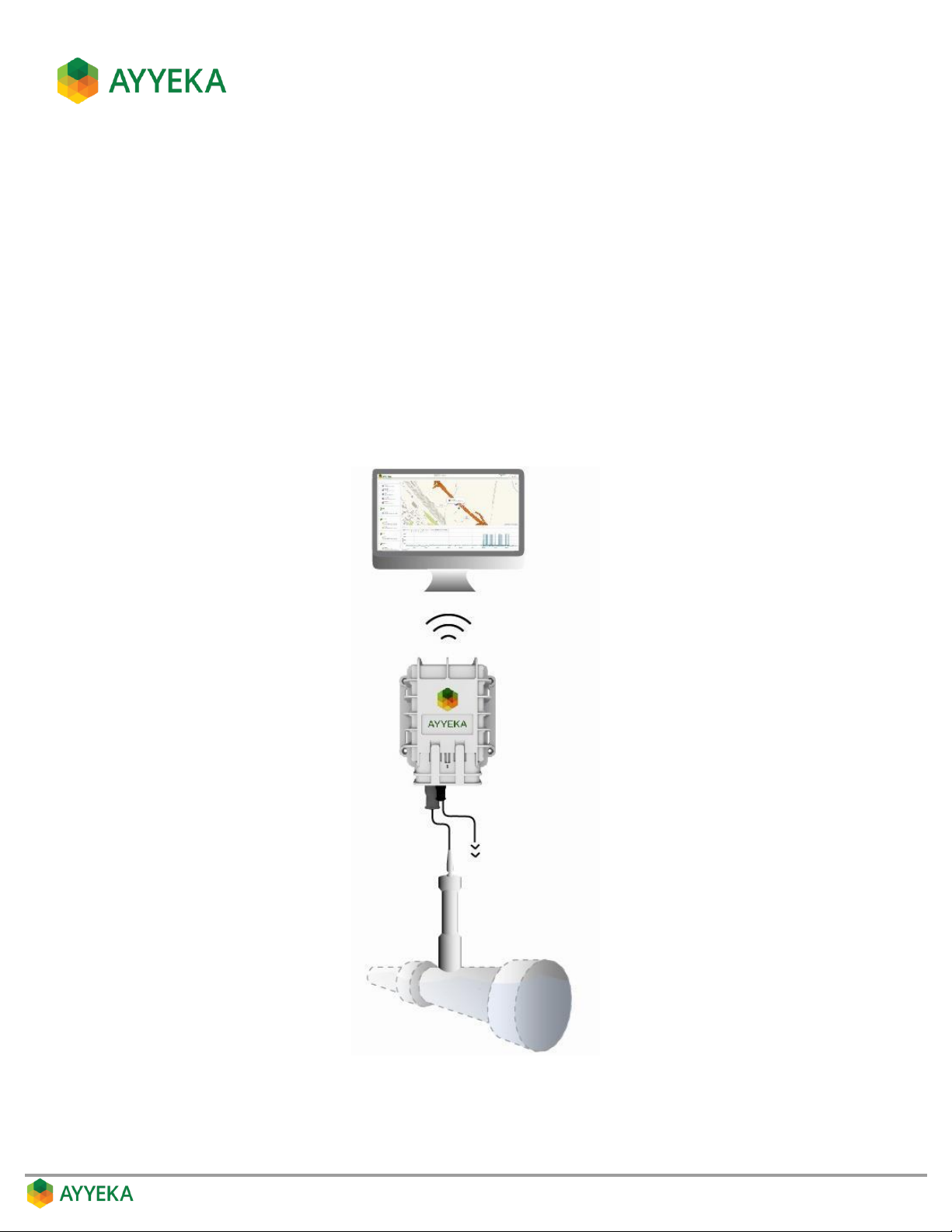
Ayyeka’s Wavelet™ is a remote infrastructure monitoring tool that delivers field data to decision makers. It is an
all-inclusive, plug-and-play system, including batteries, SIM card, sensors, and installation hardware.
After learning your specific needs, Ayyeka pre-integrates the appropriate sensors with the Wavelet data collection,
storage and communication device which is then installed onto existing infrastructure.
The data collected from the sensors is stored on Ayyeka’s secure private cloud server, and/or can be integrated
directly into your on-premises servers.
An Ayyeka web-based data management system enables you to configure the device over-the-air and program
various parameter threshold levels for email and/or SMS alerts, visualize data in real-time, and produce reports
for presentation and analysis. Using Ayyeka’s API, data can be integrated directly into your SCADA systems,
business intelligence or other analytic software.
Figure 1: Ayyeka Wavelet system
Page 11
Wavelet Kits
Each Wavelet Kit, composed of a Wavelet device and smart sensors, is targeted at a specific need in the
infrastructure sector. The intended usage dictates the type of sensors included in the kit. Ayyeka offers various kits
in each of the following categories:
Water
Wastewater
Environmental
Oil & Gas
Industrial
Wavelet Device
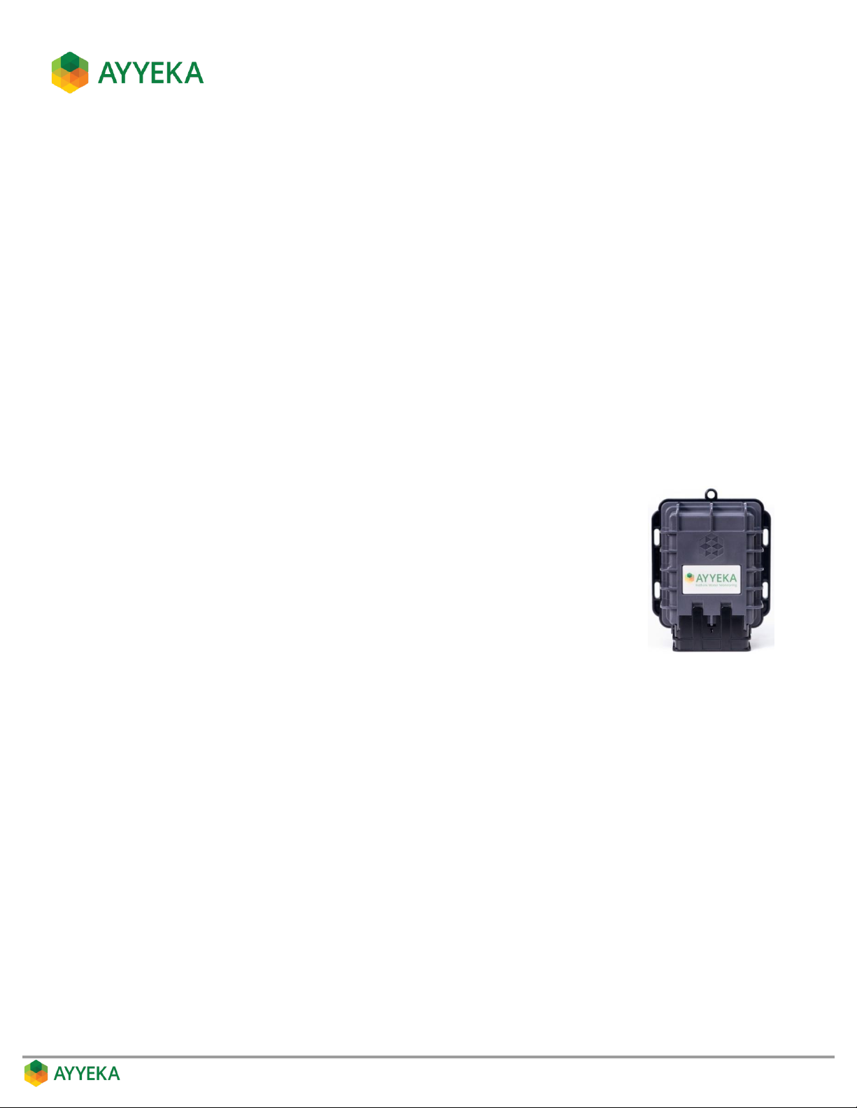
The Wavelet device periodically samples the connected sensors and transmits the data to the Ayyeka cloud or to
your on-premises server. The device supports 2G, 3G, LTE (4G), CDMA, LPWAN, Satellite, and Bluetooth low-energy
networks, and can interchangeably use the strongest available cellular signal.
The Wavelet device is powered by a field-replaceable internal battery that provides
3,500+ transmissions. Alternatively, the device can be connected to an external battery,
solar panel or permanent power source.
The Wavelet device can be mounted in various ways, including:
Affixed to a pipe, using the supplied zip ties
Affixed to a wall, using the supplied four screws and anchors
Hung on a wall, using one of the supplied screws and anchors
Sensor Integration
Each Wavelet device has three sensor connector ports and supports any combination of the following types of
sensors:
Serial
Analog
Discrete
The specific types of sensors and sensor connectors in a kit depend on the kit type.
Page 12
User Interface
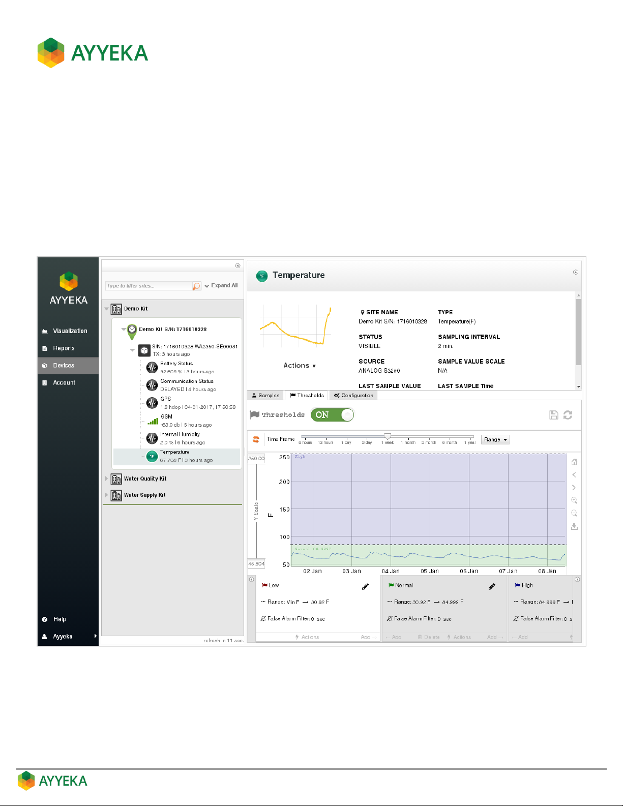
The data collected by the Wavelet device and transmitted to the Ayyeka cloud can be viewed in the Ayyeka
web-based data management system. This system enables:
Visualizing data in real-time
Generating reports for presentation and analysis
Defining threshold levels for email and/or SMS alerts for various parameters
Over-the-air remote device configuration
Receiving battery level notifications for predictive maintenance scheduling
Figure 2: Ayyeka web-based data management system
Page 13
INSTALLING THE WAVELET KIT
Assembling the Wavelet Kit
The assembly instructions depend on the type of Wavelet Kit. Refer to the Quick Start Guide corresponding to your
kit type.
Connecting to an External Power Source
If you wish to connect the Wavelet device to an external power source, follow these guidelines:
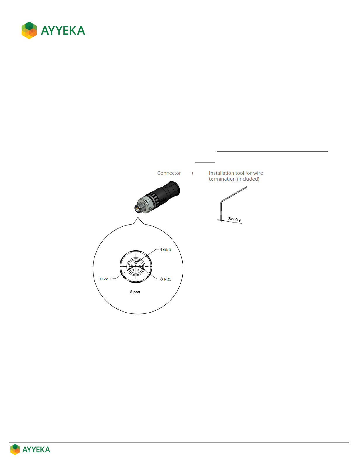
Use a 42-00009 (SAL - 8 - RSC3-S) CONEC connector (refer to Appendix A: Connector 42-00009 datasheet).
Perform power connector assembly as illustrated in Figure 3.
Figure 3: Power connector assembly instructions
Use a cable with a round and even cross-section having the following specifications:
Cable wire cross section surface area: 0.14-0.5 mm
2
Wire gauge: AWG 26-20
Cable diameter Ø: 4-5.5 mm
Page 14
Turning the Wavelet On
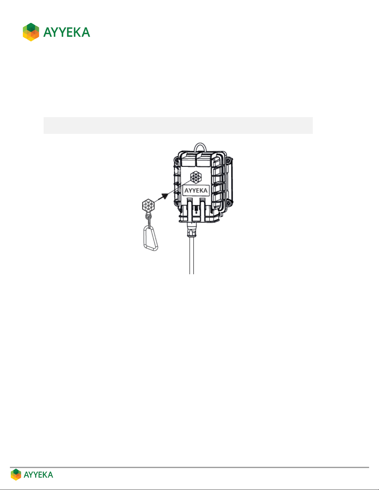
The Wavelet device is delivered in hibernation mode. To turn it on, press the magnetic activator, provided in the
Wavelet Kit, onto the Ayyeka logo appearing on the Wavelet device.
The Wavelet device turns on and performs a 10-minute calibration process, after which it starts operating in
normal mode.
Note: Every time you press on the Ayyeka logo with the magnetic activator, the device
performs a calibration process.
Figure 4: Turning Wavelet device on
Page 15

AYYEKA WEB-BASED DATA MANAGEMENT SYSTEM
The Ayyeka data management system provides the following:
Visualization window – enables viewing your site deployment from the macro to the micro level
Reports window – enables generating reports and exporting them for viewing and sharing
Devices window – enables you to view and manage all your Sites, Devices and Data Stream configurations.
Previously, this was part of the Management tab
Account window – enables you to manage all Organizations, Users and User Groups. Previously, this
functionality was provided in the Management tab
API window – enables access to the Ayyeka REST API and SOAP API, which provide programmatic access
to your Wavelets' information
Accessing the Data Management System
To access the Ayyeka data management system:
Navigate to home.ayyeka.com and enter your Ayyeka credentials. The Initial Visualization window
appears.
Understanding Sites’ Hierarchy
Your system (also called an account) is organized hierarchically as follows:
Account
Organization(s)
Site(s)
Device(s)
Data streams(s)
Page 16
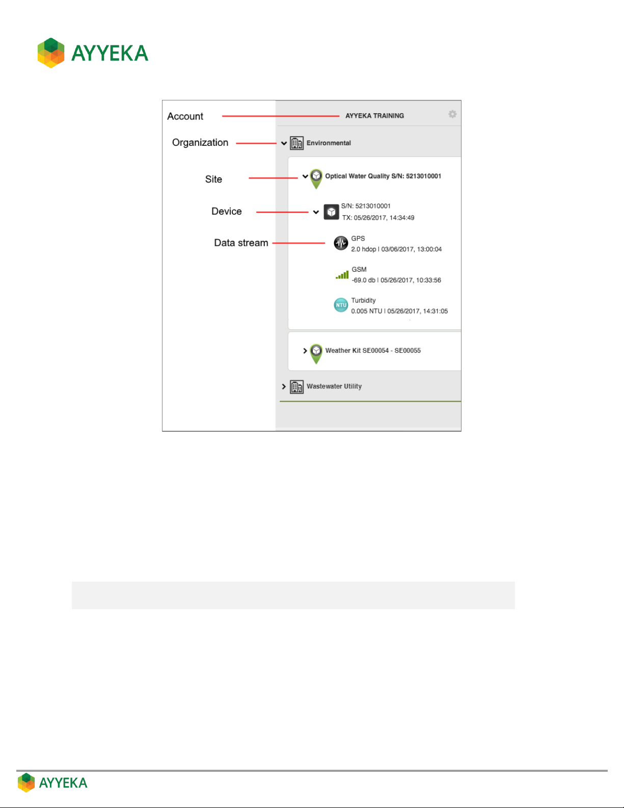
Figure 5: Account hierarchy
In the example shown above, the AYYEKA TRAINING account consists of two organizations, Environmental and
Wastewater Utility. Environmental manages two sites. A site is a representation of a physical location. Typically, each
site includes one device. In some instances, multiple devices might be assigned to a single site. Each device
generates and subsequently transmits data streams (time-stamped data) from one or more sensors (such
as pressure, turbidity, conductivity, etc.) integrated with the device.
Every account’s hierarchy is pre-defined to match the actual deployment of its devices and their sensors. The only
hierarchy changes an account owner can make is to add organizations, and unassign/assign sites to organizations.
Note: The Organization level is optional. If no organizations are defined, all sites are
grouped directly under the Account level. This is common in small accounts.
Page 17

Understanding User Roles
The system supports two sets of roles: Account roles and Organization roles.
Account roles give permissions with regards to all account assets.
Organization roles give permissions with regards to a specific organization’s assets.
Account roles
Each role level is given the permissions given to lower-level roles, plus some additional permissions. The roles,
from lowest to highest, include:
No Access - Alerts Only – Can only receive threshold alerts from account devices.
Account Operator – Can also view sites and streams of this account.
Account Analyst – Can also generate reports.
Account Engineer – Can also manage all sites and streams of this account.
Account Administrator – Can also set device configuration for all devices in this account.
Account Owner – Can also manage all users, groups and organizations of this account.
Organization roles
Each role level is given the permissions given to lower-level roles, plus some additional permissions. The roles,
from lowest to highest, include:
No Access - Alerts Only – Can only receive threshold alerts from organization devices.
Organization Operator – Can also view sites and streams of this organization.
Organization Analyst – Can also generate reports.
Organization Engineer – Can also manage all sites and streams of this organization.
Organization Administrator – Can also set device configuration for all devices in this organization.
Organization Owner – Can also manage all users and groups of this organization.
Getting Started
After becoming acquainted with the Sites’ Hierarchy and the available User Roles, it is recommended to perform the
following to set up your account:
1. If you are an account owner you may wish to create or edit organizations. Refer to Managing
Organizations.
2. Create or edit users, giving them the necessary permissions. Refer to Managing Users.
3. Create user groups, which define who receives alerts when data thresholds are exceeded. Refer to
Managing User Groups.
4. View your sites (groups of Wavelet devices), and edit their settings if necessary. Refer to Managing Sites.
Page 18

5. Manage the various data streams received from each specific sensor:
Trim the raw data; then view the formula for converting raw data into engineering units, and edit if
necessary. Refer to Viewing and Editing the Treatment of Raw Data.
View the samples table, and hide values that are not real values. Refer to Viewing and Filtering
Samples.
Set thresholds. When a threshold is exceeded, an alert is sent to the corresponding user group, and
certain data stream actions can be taken. Refer to Configuring Data Stream Thresholds.
View and optionally change a stream’s sampling interval; this is the rate at which the Wavelet
samples the relevant sensor for data. Refer to Managing a Stream’s Sampling Interval.
6. View the settings of your Wavelet devices, and modify if necessary. Refer to Managing Devices.
Page 19
USING THE AYYEKA VISUALIZATION WINDOW
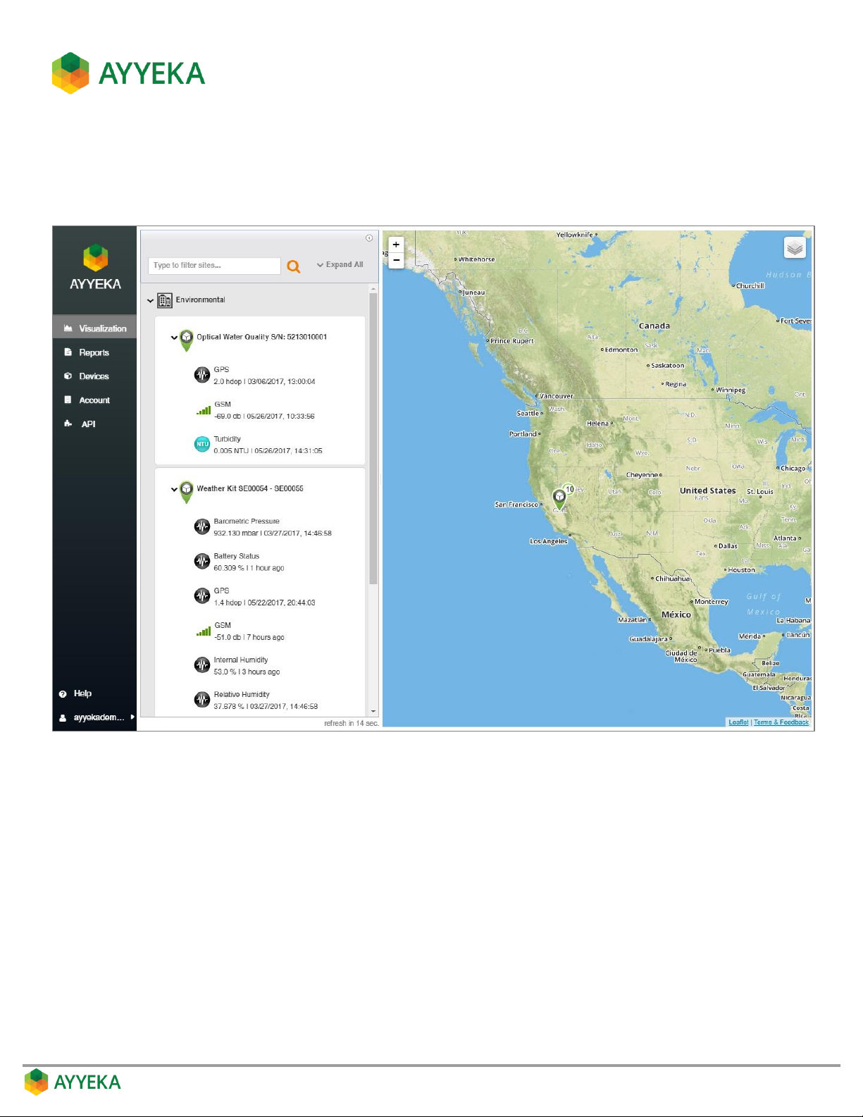
Click the Visualization tab to display the initial Visualization window.
Figure 6: Initial Visualization window
Page 20
The Visualization window is composed of a sidebar, Sites Tree pane and a right pane.
Side bar – links to the 5 main views: Visualization, Reports, Devices, Account, API. The available views
depend on your permissions (role).
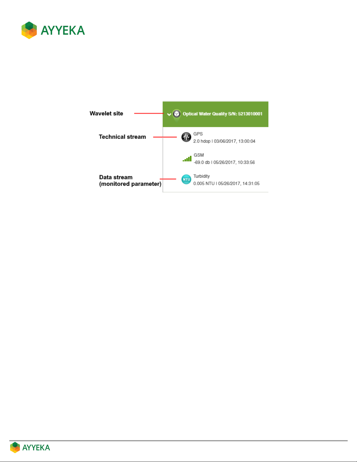
Sites Tree pane – lists all Wavelet sites and their data streams:
The Sites Tree pane includes also a search box, which you can use to search for your sites.
If there are more than 5 search results, the results will not be displayed. In that case you need to refine
your search criteria.
Right pane - shows a zoomed-out map displaying clusters of data streams.
Using the zoom controls, you can zoom in for greater detail, down to an individual site and its data
streams.
Page 21
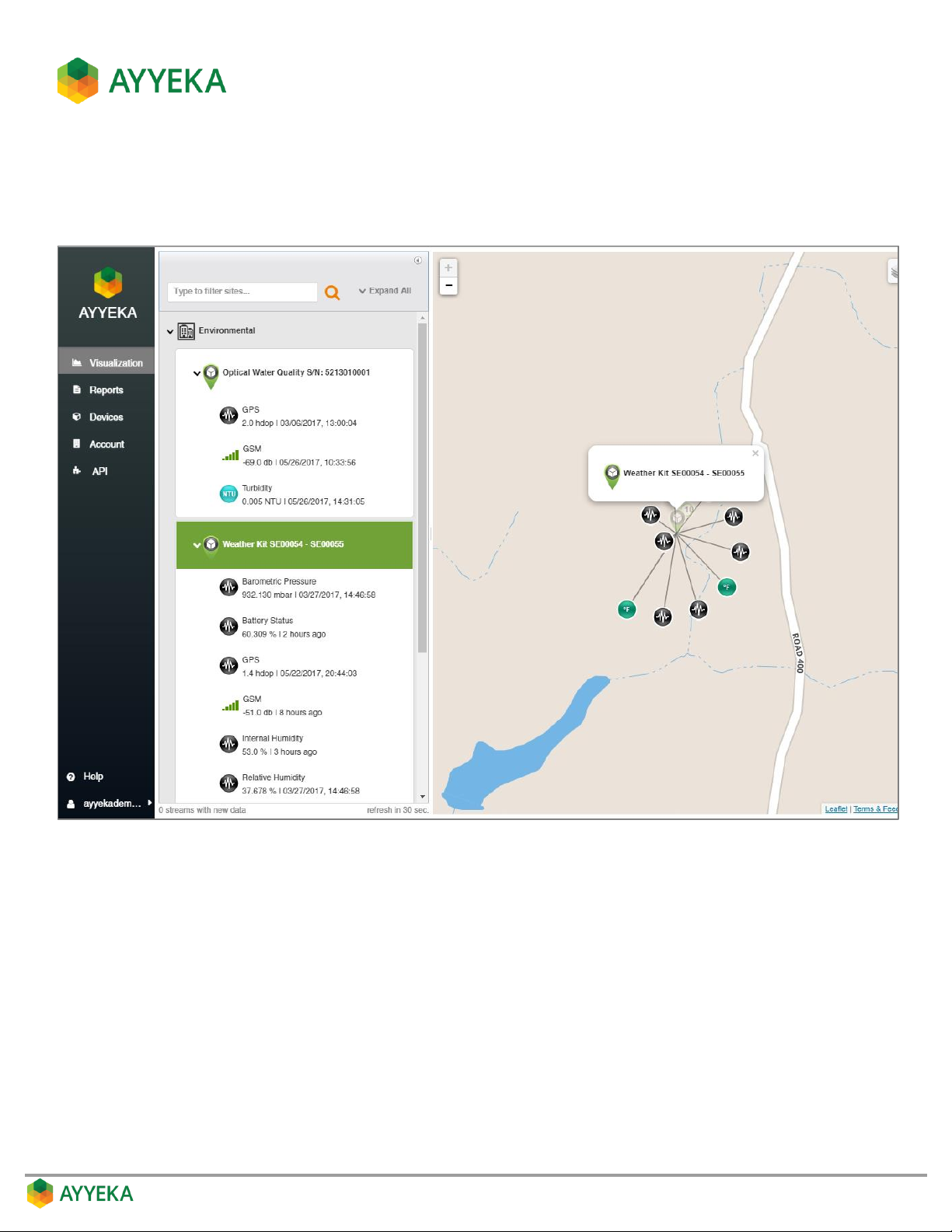
Viewing Site Information
1. To view the data from a specific Wavelet site, click the site in the Sites Tree pane or on the map.
The right pane refreshes to show the site and its data streams.
Figure 7: Viewing an individual site
2. To view the data sent from a specific data stream, click the data stream in the Sites Tree pane or on the
map.
The right pane splits, displaying the data as a chart in the bottom half of the pane.
Page 22
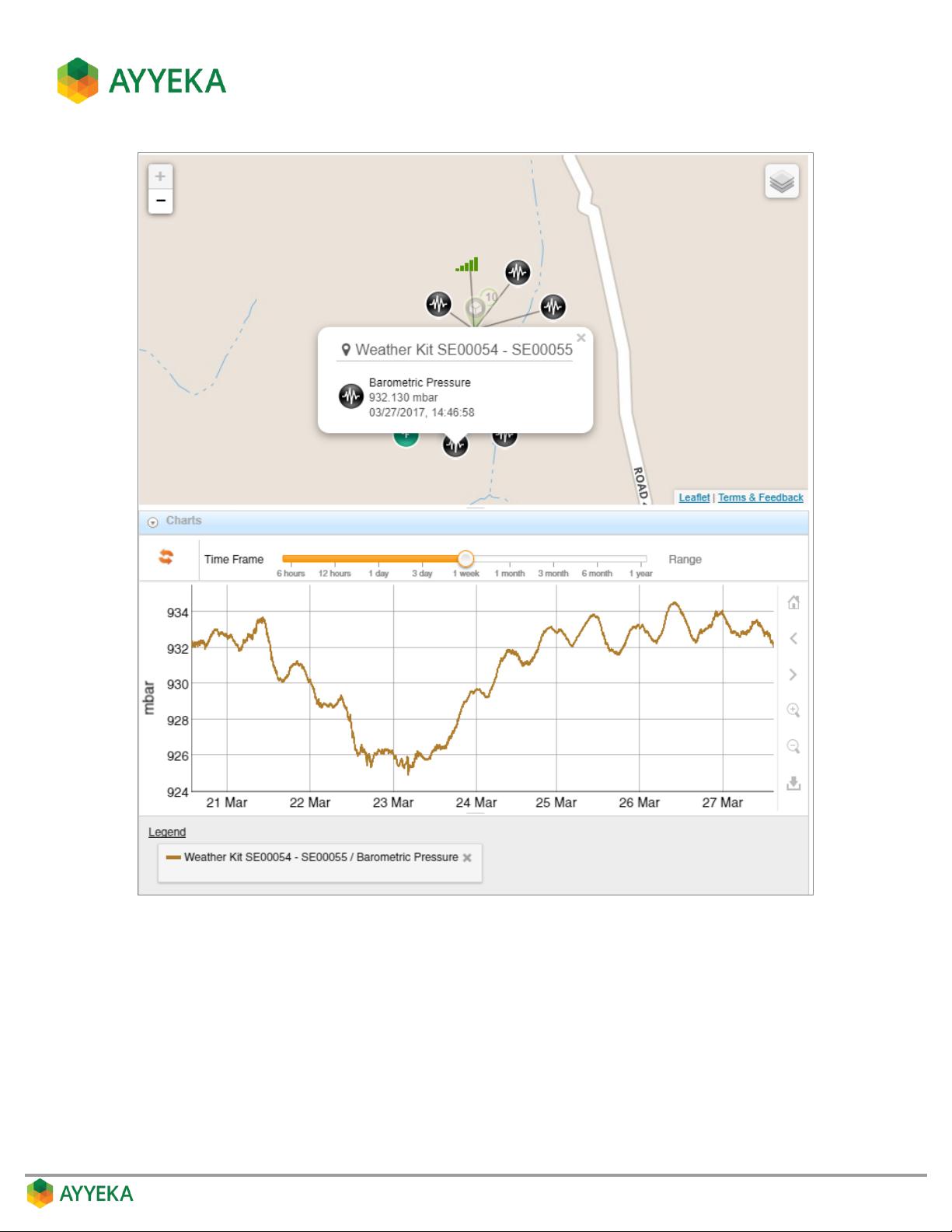
Figure 8: Viewing an individual data stream
Page 23
Understanding the Data Stream Chart
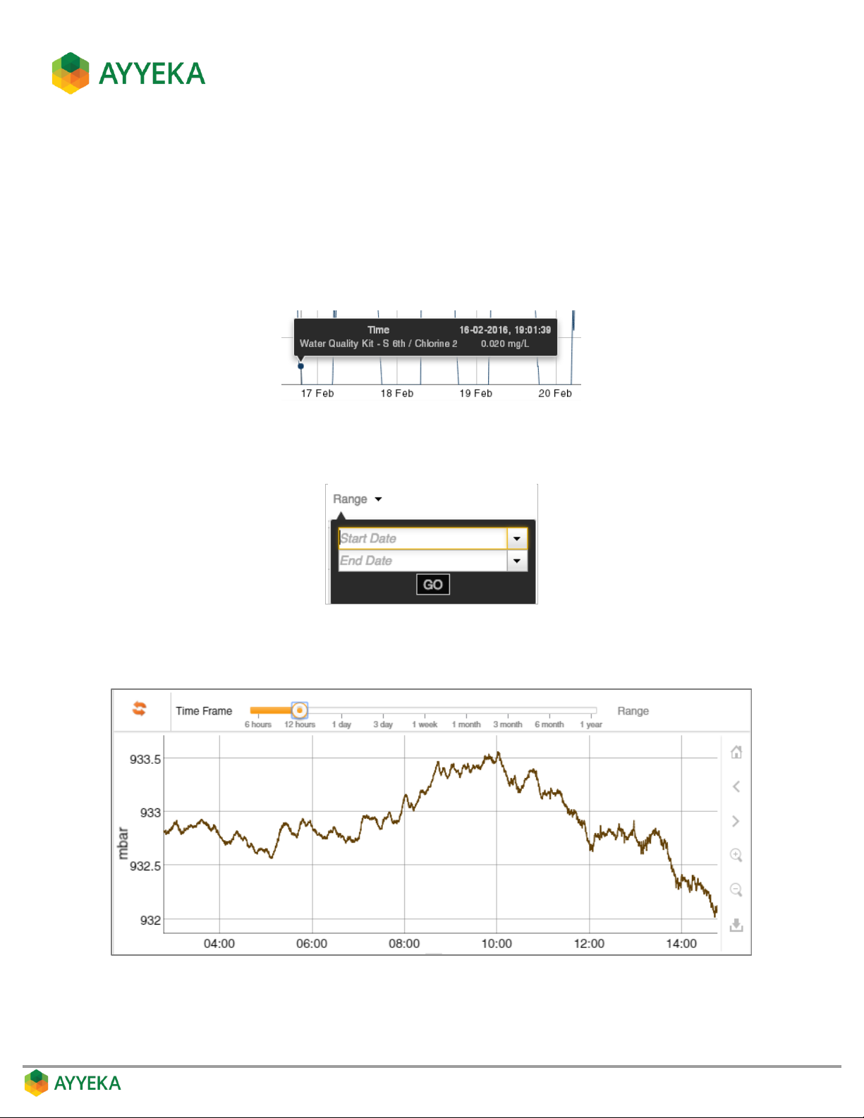
Hovering over a point in the chart displays a tool tip with the following information:
Timestamp
Site name
Type of data stream (such as Pressure, Level, etc.)
The reading
Setting the Time Range
You can set the start and end date for the chart by clicking the Range drop-down and setting the dates.
Setting the Time Frame
You can set the time frame shown in the window by selecting the desired time frame in the Time Frame selector.
Page 24
Using the Zoom and View tools
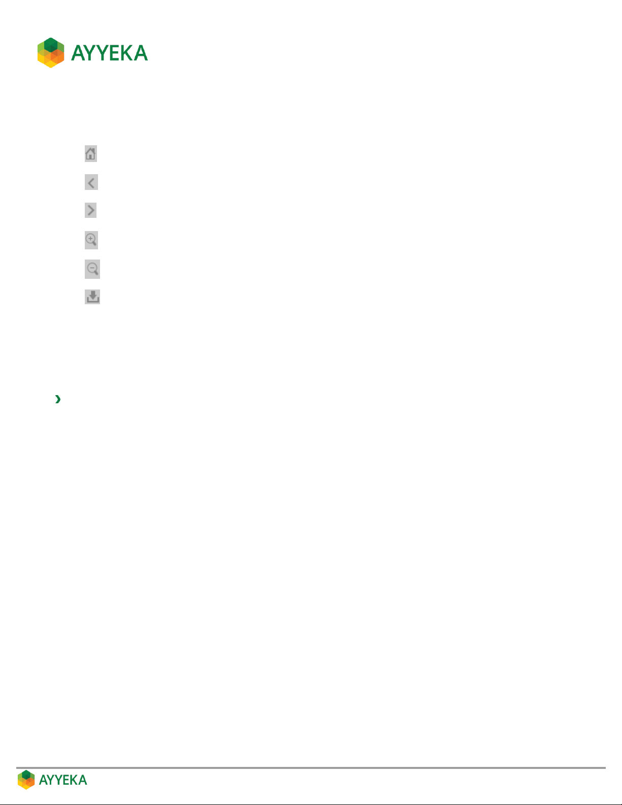
You can adjust the view using any of the following tools, appearing to the right of the chart:
Zoom to initial view (1 week)
Pan left
Pan right
Zoom in
Zoom out
Download as .png. This opens the graph as a PNG file in a new browser tab.
Comparing Data Streams
You can also compare the readings obtained from multiple data streams by displaying them in same chart. Up to
five data streams of up to two different types can be displayed in the same chart.
To compare data streams:
1. Click the first data stream in the Sites Tree pane.
The right pane splits, displaying the data in a chart in the bottom half of the pane.
2. Click the second data stream in the Sites Tree pane.
The data appears in the same chart in the bottom half of the right pane.
3. Repeat step (2) as desired. If you select more than five data streams in all, or more than two different
types of data streams, the data from the additional data streams will appear in a new tab.
Page 25
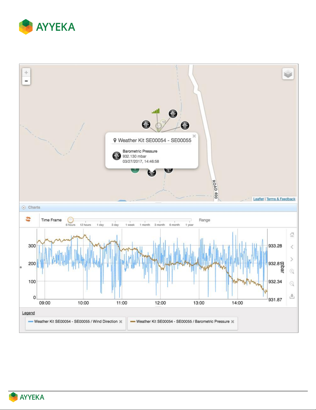
The following example shows a comparison of two data streams from the same site.
Figure 9: Comparing two data streams
Page 26
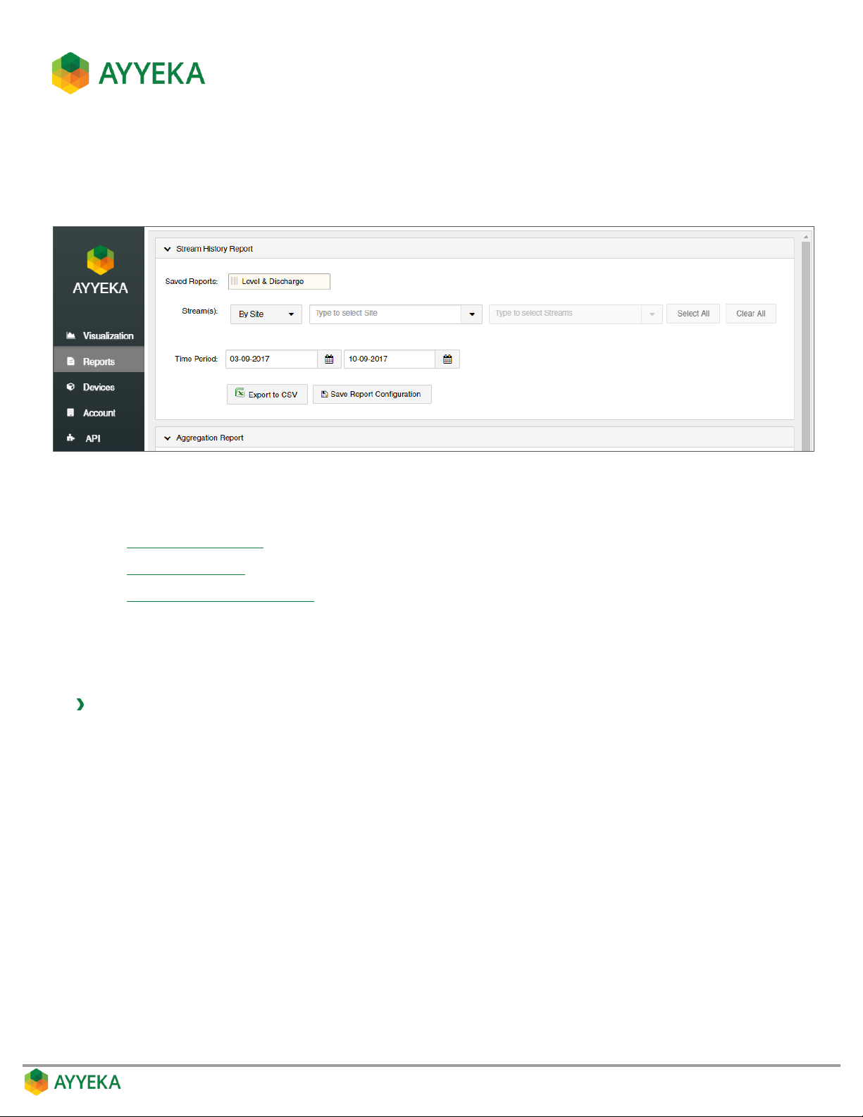
GENERATING REPORTS
Using the Reports tab you can easily create various types of reports, and export them to Excel.
Figure 10: Reports Tab
You can create the following types of reports:
Stream History Report
Aggregation Report
Custom Stream History Report
Stream History Report
This type of report displays the history of one or more data streams of a particular type.
To create a Stream History report:
1. Click Reports in the side bar.
2. In the Stream History Report pane:
a. Select whether to specify streams By Site or By Stream Type.
b. If you selected to specify streams By Site, specify the site, and then specify stream(s) in the site.
c. If you selected to specify streams By Stream Type, specify the stream type, and then specify
stream(s) of that type.
d. Specify the reporting Time Period.
Page 27
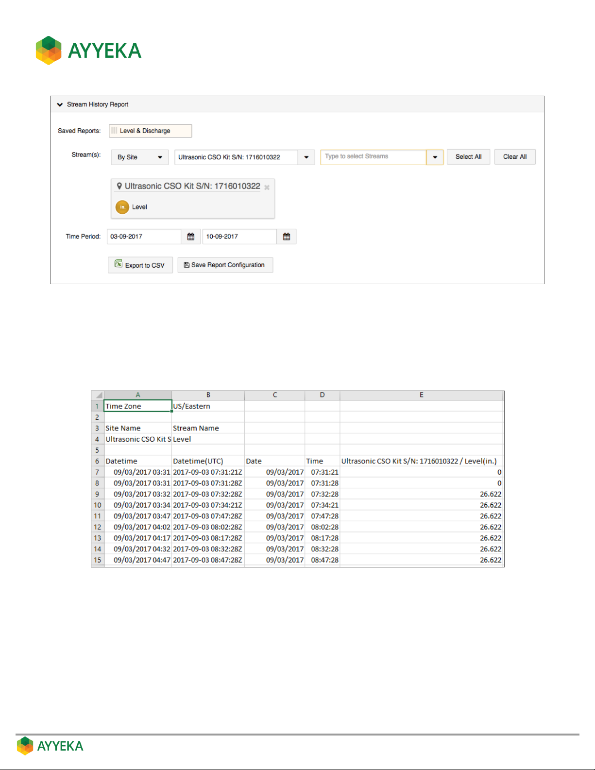
Figure 11: Stream History Report - Defining Report Criteria
3. Click Save Report Configuration if you wish to save this specific report generation criteria, and enter a
descriptive name for the report type.
4. Click Export to CSV. A CSV file is created, showing the history of the selected streams during the
selected time period.
Figure 12: Stream History Report – Example
Page 28

Aggregation Report
The Aggregation report enables viewing a statistical analysis of the readings obtained in one or more data streams
of a specific type.
To create an Aggregation report:
1. Click Reports in the side bar.
2. In the Aggregation Report pane:
a. Select whether to specify streams By Site or By Stream Type.
b. If you selected to specify streams By Site, specify the site, and then specify stream(s) in the site.
c. If you selected to specify streams By Stream Type, specify the stream type, and then specify
stream(s) of that type.
d. Specify the reporting Time Period.
3. Select the aggregation period - from 1 min intervals to 1 month intervals.
4. If you select to run the report for multiple streams, you can:
a. Select which statistical analysis function to run on those streams: either Sum, Average, Min, Max or
Standard Deviation
b. Specify Separate Streams if you wish to run a separate analysis for each of the specified streams.
For example, if you had specified Stream1 and Stream2 and chosen Average, then:
Choosing Separate Streams will provide the average of all Stream1 recorded values in one
column, and the average of all Stream2 recorded values in a second column.
Not choosing Separate Streams will provided an average of all Stream1 and Stream2 recorded
values, in a single column.
Note that you can generate an Aggregation report for multiple streams only if all those streams are of
the same type (such as Level), and use the same unit of measurement (such as inches).
Page 29
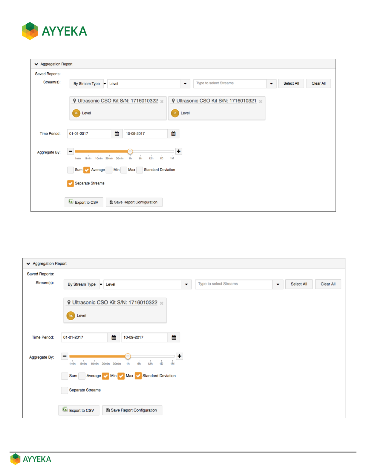
Figure 13: Aggregation Report - Defining Report Criteria for Multiple Streams
5. If you select to run the report for a single stream, you can run any combination of the following
statistical analysis functions: Sum, Average, Min, Max or Standard Deviation.
Figure 14: Aggregation Report - Defining Report Criteria for a Single Stream
Page 30
6. Click Save Report Configuration if you wish to save this specific report generation criteria, and enter a
descriptive name for the report type.
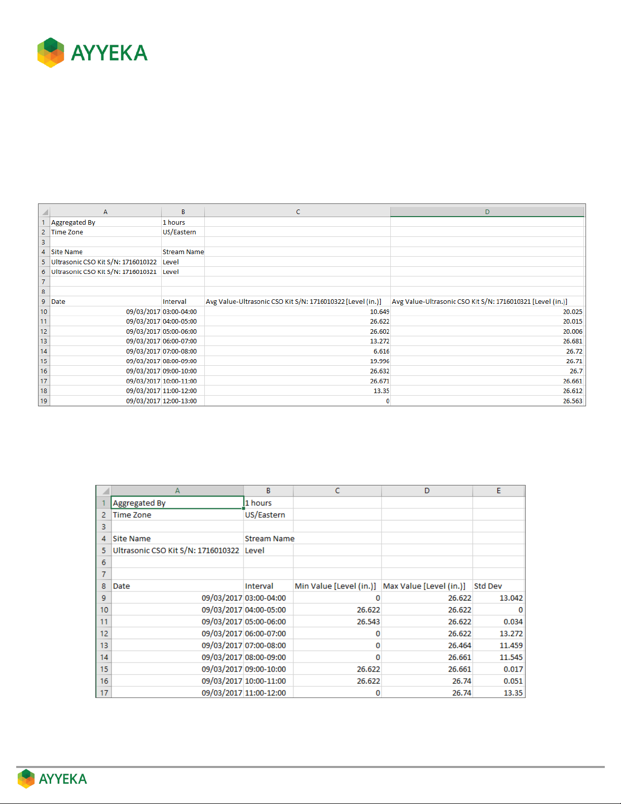
7. Click Export to CSV. A CSV file is created, showing the results of the statistical analysis for the selected
period. For example:
If you had specified two streams, the Average function, and Separate Streams in the report
criteria, the resultant report will look similar to the following:
Figure 15: Aggregation Report – Example for Multiple Streams
If you had specified a single stream, and the Min, Max and Standard Deviation functions in the
report criteria, the resultant report will look similar to the following:
Figure 16: Aggregation Report – Example for a Single Stream
Page 31
Custom Stream History Report
This type of report enables customizing the display of any data streams’ history. You can set which fields will
appear in the report, how the fields should be delimited, etc. This is very useful if you need to export data from
the report into a system that supports a specific data structure only.
To create a Custom Stream History report:
1. Click Reports in the side bar.
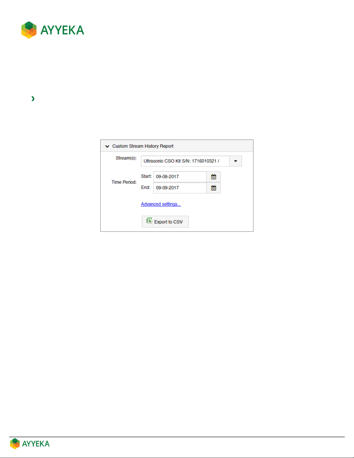
2. In the Custom Stream History Report pane, select the specific streams you wish to view, and the
reporting time period.
Figure 17: Custom Stream History Report - Defining Streams and Time Period
Page 32
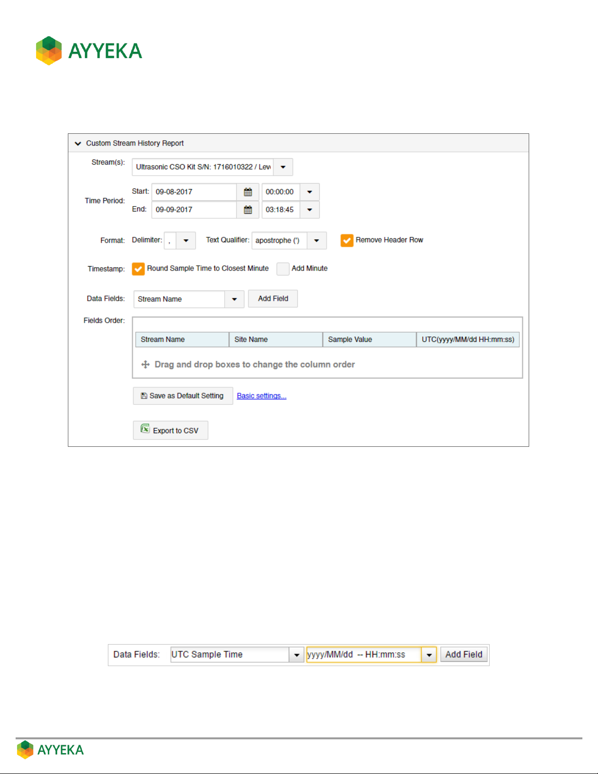
3. Click Advanced Settings to define the type of information to include in the report, as well as how it will
be displayed.
Figure 18: Custom Stream History Report – Specifying Fields and Method of Display
a. Set the Format Delimiter.
b. Set the Text Qualifier.
c. Specify whether to Remove Header Row.
d. Specify whether to Round Sample Time to Closest Minute in the timestamp, and whether to Add
Minute.
e. For each data field you wish to include in the report:
Select the field in the Data Fields drop-down.
If a format drop-down appears, select a format. Note that you can edit the format directly in the
window.
Click Add Field.
Page 33
f. In the Fields Order section, you can change the order in which columns will appear, by dragging and
dropping column titles.
g. Optionally click Save as Default Settings; the settings you defined will become the new default
settings for the Custom Stream History Report.
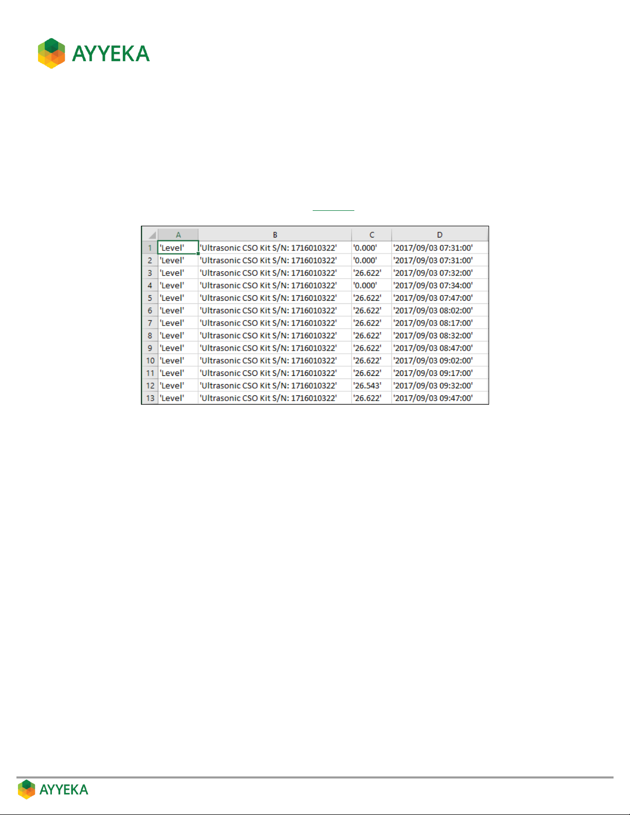
4. Click Export to CSV. A CSV file is created, showing the history of the selected streams during the
selected time period.
For example, for the report criteria defined in Figure 18, the resultant CSV report file is as follows:
Figure 19: Custom Stream History Report - Example with no header row
Page 34
MANAGING SITES
A site is a group of devices in close proximity. This section describes how to view and edit site information.
Viewing a Site
To view site information:
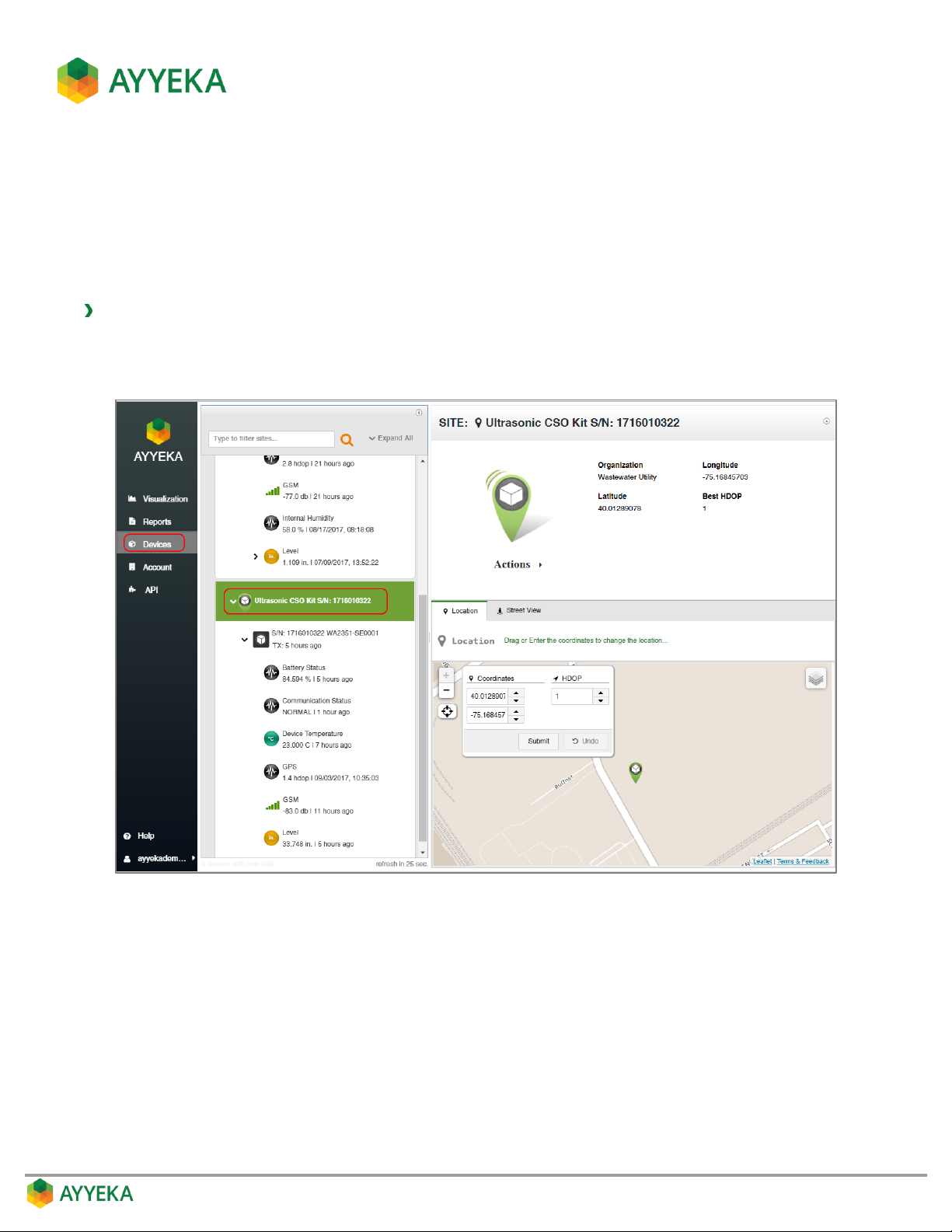
1. Click Devices in the sidebar.
2. In the Sites Tree pane, click the site name.
Figure 20: Selecting a site
The site’s location and information appears in the right pane. This includes:
The site name, the organization to which it belongs, and its latitude and longitude coordinates.
A map view, showing the location of the site. You can change the view by clicking the layers icon at
the top right corner of the view.
A street view from Google of the site’s location.
Page 35
Editing a Site
Changing the Site Name and Organization
You can change a site’s name and the organization to which it belongs.
To change a site’s name and organization:
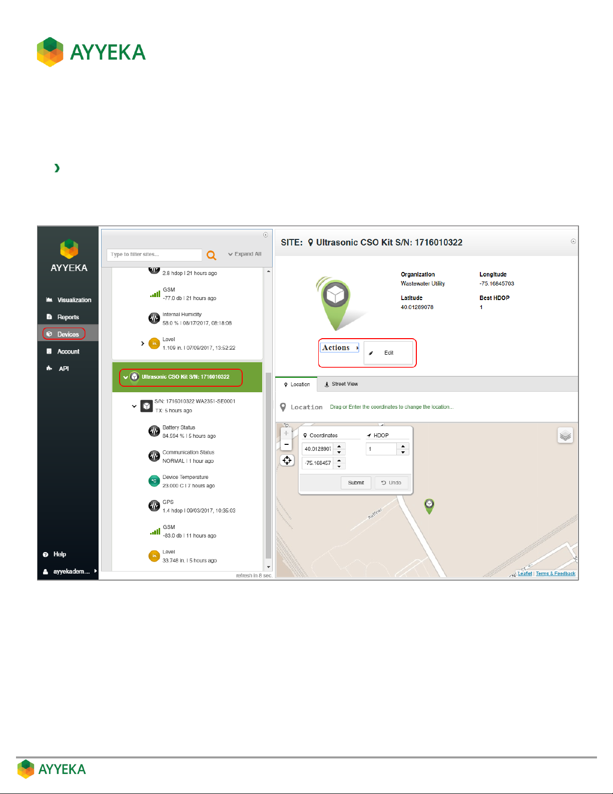
1. Click Devices in the sidebar, and click the site name in the Sites Tree pane.
2. In the right pane, click Actions under the site icon, and select Edit.
Figure 21: Selecting to edit a site
Page 36
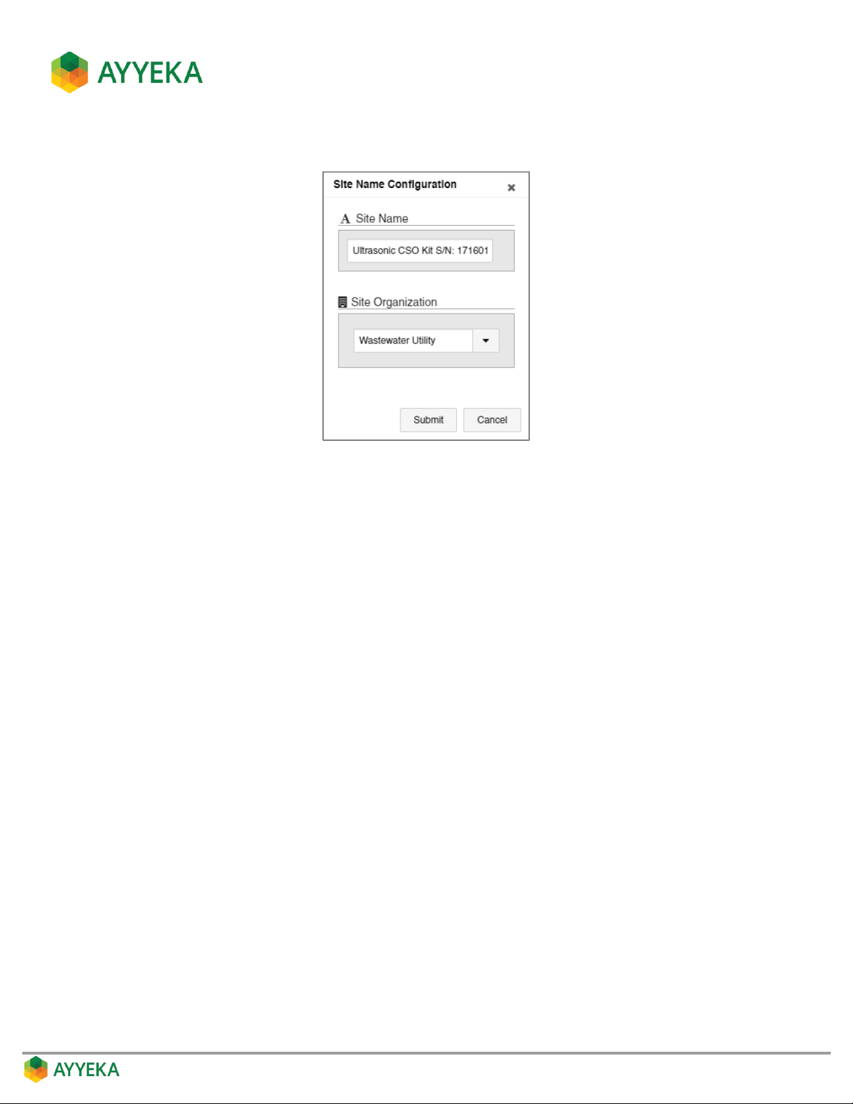
The Site Name Configuration window appears.
Figure 22: Changing site name or organization
3. In the Site Name Configuration window, you can:
Change the name of the site.
Change the organization to which the site belongs. Note that a site can belong to only one
organization.
4. Click Submit.
Page 37
Changing the Site Location
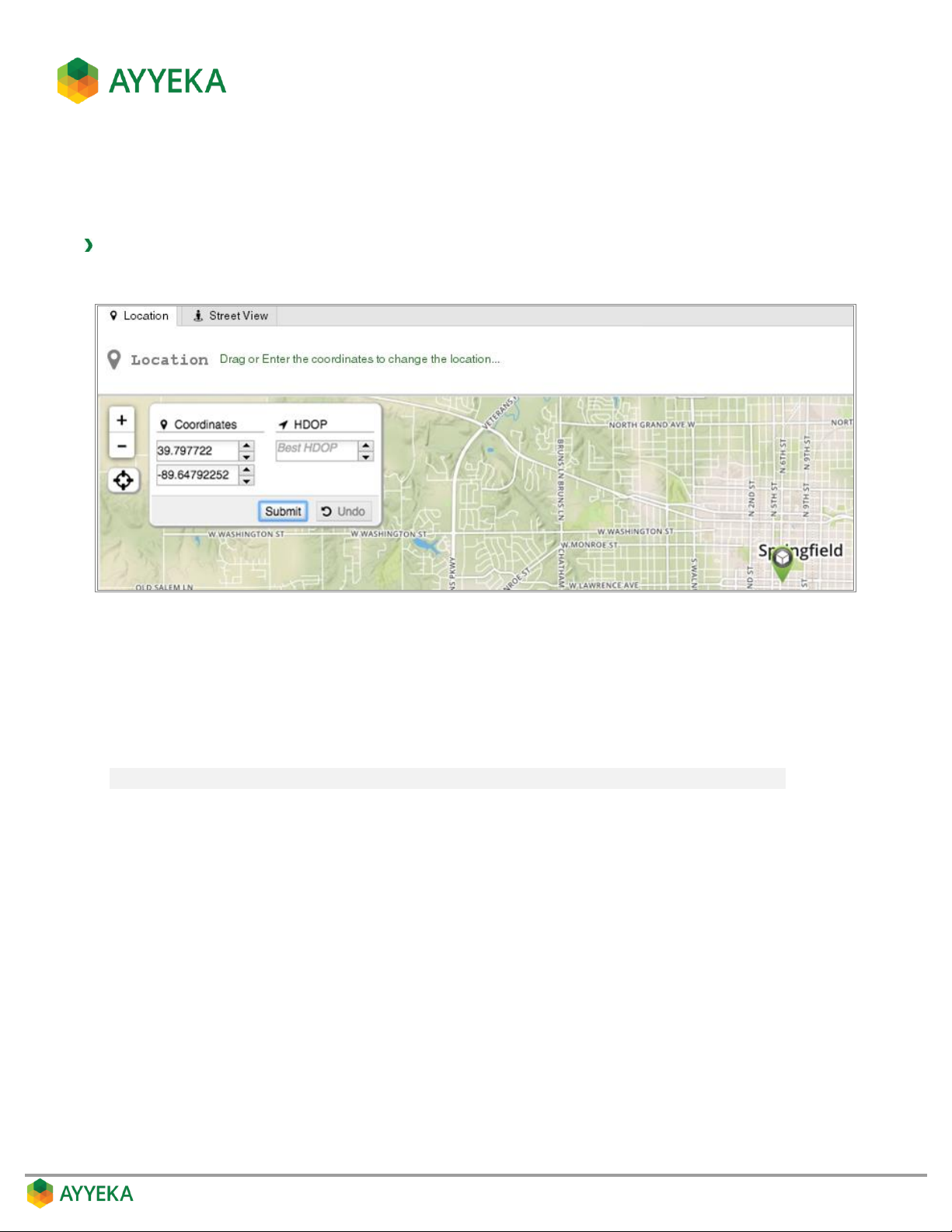
You can change the site’s location by dragging and dropping it in the map, or by entering coordinates in the
Coordinates fields.
To change a site’s location:
1. Click Devices in the sidebar, and click the site name in the Sites Tree pane.
Figure 23: Changing site location
2. In the map appearing in the right pane, you can do any of the following:
Drag and drop the site icon in the map.
Edit the coordinates displayed in the Coordinates fields. The coordinates originally displayed are
the site location as transmitted by the devices in the site.
Note: Do not edit the HDOP field. It is reserved for future use.
Page 38
MANAGING DEVICES
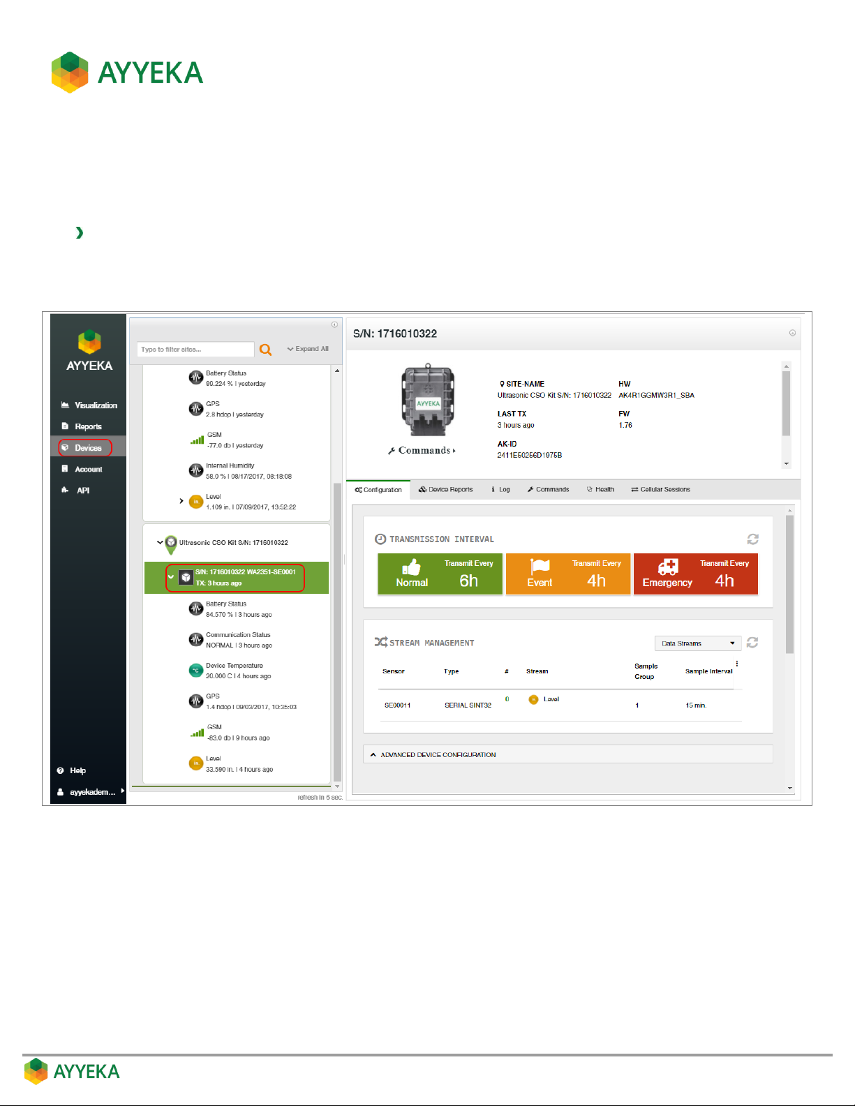
You can view and change device settings such as the device transmission rate, and view varied device history and
health information.
To view and edit device settings:
1. Click Devices in the sidebar.
2. In the Sites Tree pane, click the device name.
Figure 24: Selecting a device
Device information and configuration options appear in the right pane. This includes:
The device’s serial number, part number, its site name, last transmission time, hardware version and
firmware version, Ayyeka ID and ICC ID (=ID of the SIM card).
The ability to send various commands to the device.
Stream management information – an overview of the mapping of physical streams to logical
channels.
Page 39
Several tabs, enabling:
Managing Device Configuration
Viewing the Files Sent and Received by the Device
Viewing the Device Event Log
Viewing the Commands Sent to the Device
Viewing the Health of the Device
Viewing Device Cellular Information
Managing Device Configuration
The device’s Configuration tab enables viewing and changing device configuration definitions. With the exception
of the actions described in the following sub-sections, we recommend not changing these definitions without
consulting with Ayyeka by contacting [email protected].
Setting the Device Transmission Intervals
The device transmission interval defines how often the device transmits the data gathered by its sensors.
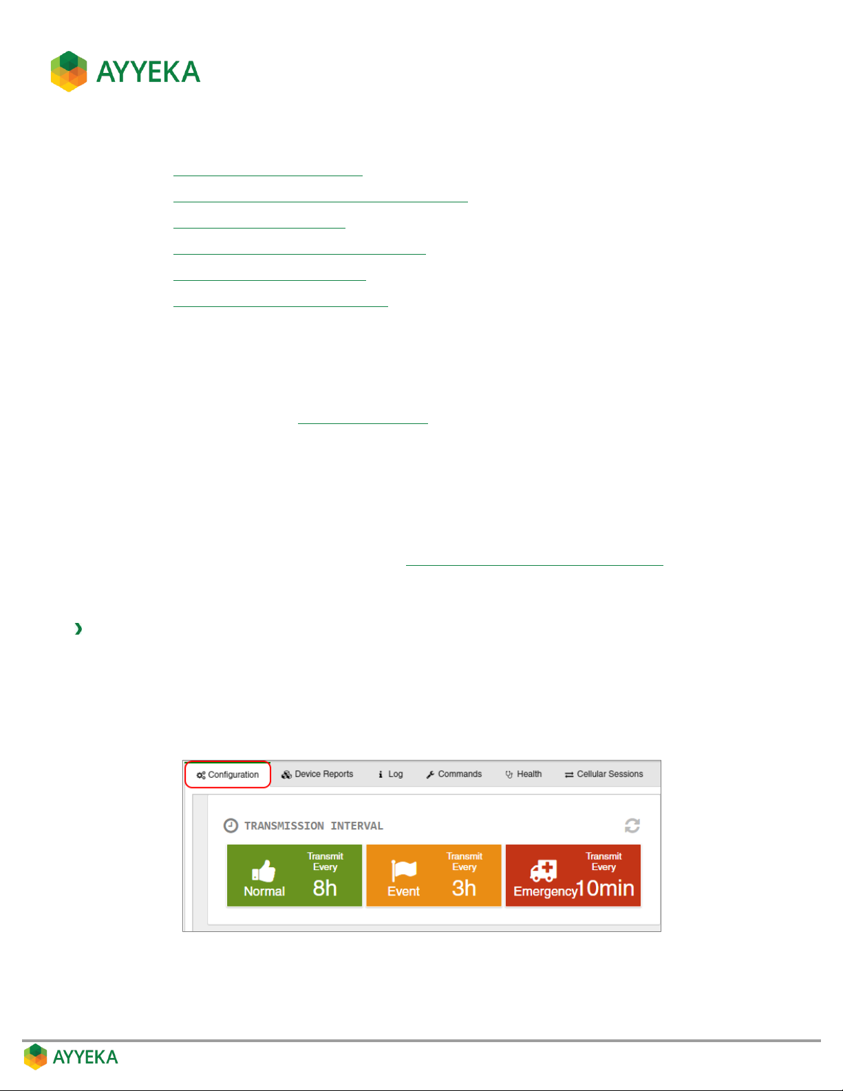
For every device you can set 3 transmission intervals: Normal, Event and Emergency. Transmission interval
Normal is the default interval. Transmission intervals Event and Emergency are two alternate intervals. Data is
always transmitted at the Normal rate, unless you specify a different rate – either Event or Emergency – when
readings fall within a threshold range (as described in Setting a Threshold’s Transmission Interval).
When setting transmission intervals, keep in mind that very short transmission intervals consume a large amount
of power and network resources.
To view or set the device transmission intervals:
1. Click Devices in the sidebar.
2. In the Sites Tree pane, click the device name.
3. In the right pane, click the Configuration tab.
The currently-defined transmission intervals are displayed.
Figure 25: Viewing the defined transmission intervals
Page 40
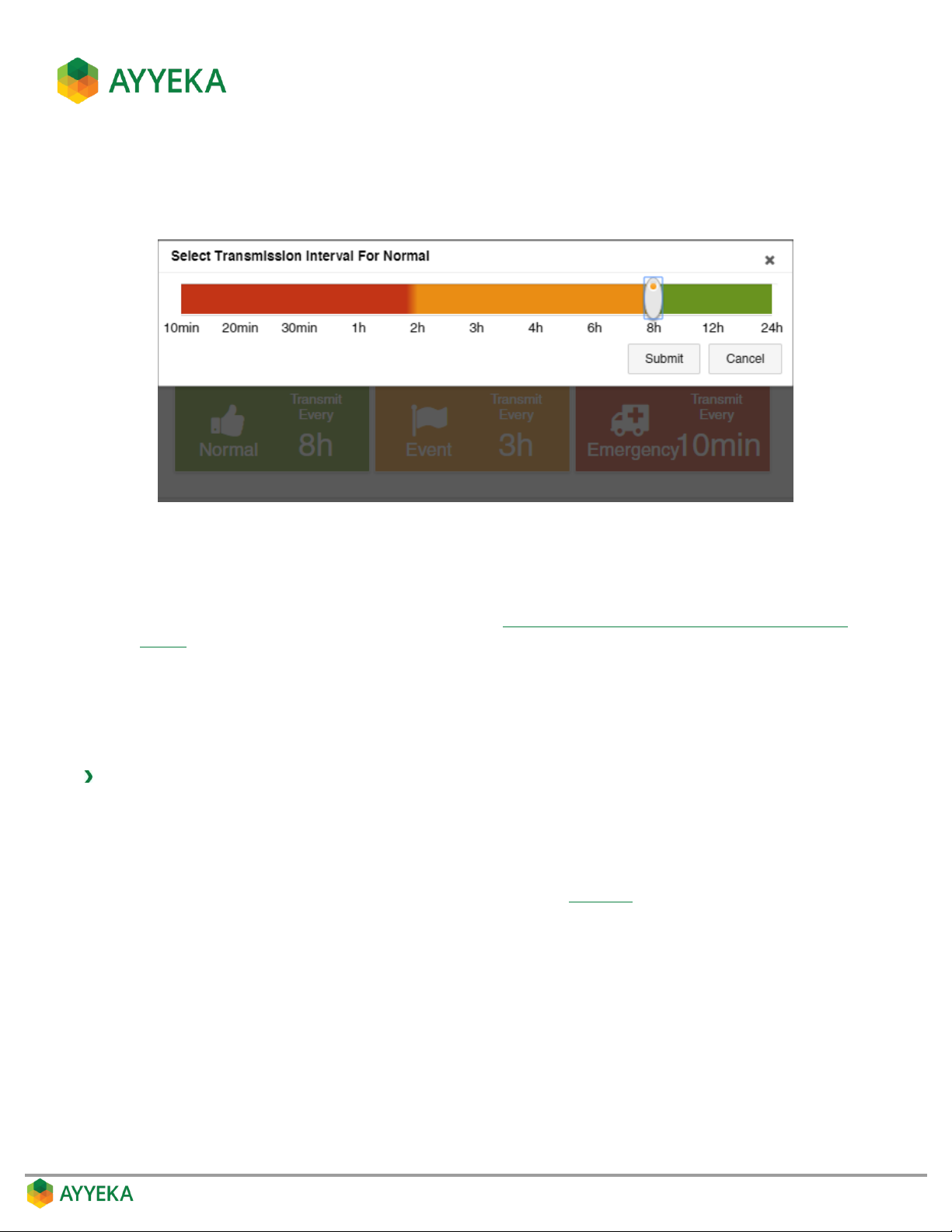
4. Click inside the box of the transmission interval you wish to change. For example, to change the Normal
transmission interval, click inside the green box.
A Select Transmission Interval for Normal window appears, with a slider for setting the interval length.
Figure 26: Changing a transmission interval using the slider
5. Set the transmission interval time, and click Submit.
Note that the slider enables choosing from among the default intervals. If you wish to set the interval to
a value that does not appear in the slider, refer to Setting a Device Transmission Interval to a Custom
Setting.
Note also that the changes won’t take effect and won’t be visible on this screen until the Wavelet next
communicates with the server.
Setting a Device Transmission Interval to a Custom Setting
To set a device transmission interval to a custom setting:
1. Click Devices in the sidebar.
2. In the Sites Tree pane, click the device name.
3. In the right pane, click the Configuration tab.
The currently-defined transmission intervals are displayed (Figure 25).
4. Scroll to the bottom of the Configuration tab, and click Advanced Device Configuration to expand this
section.
Page 41
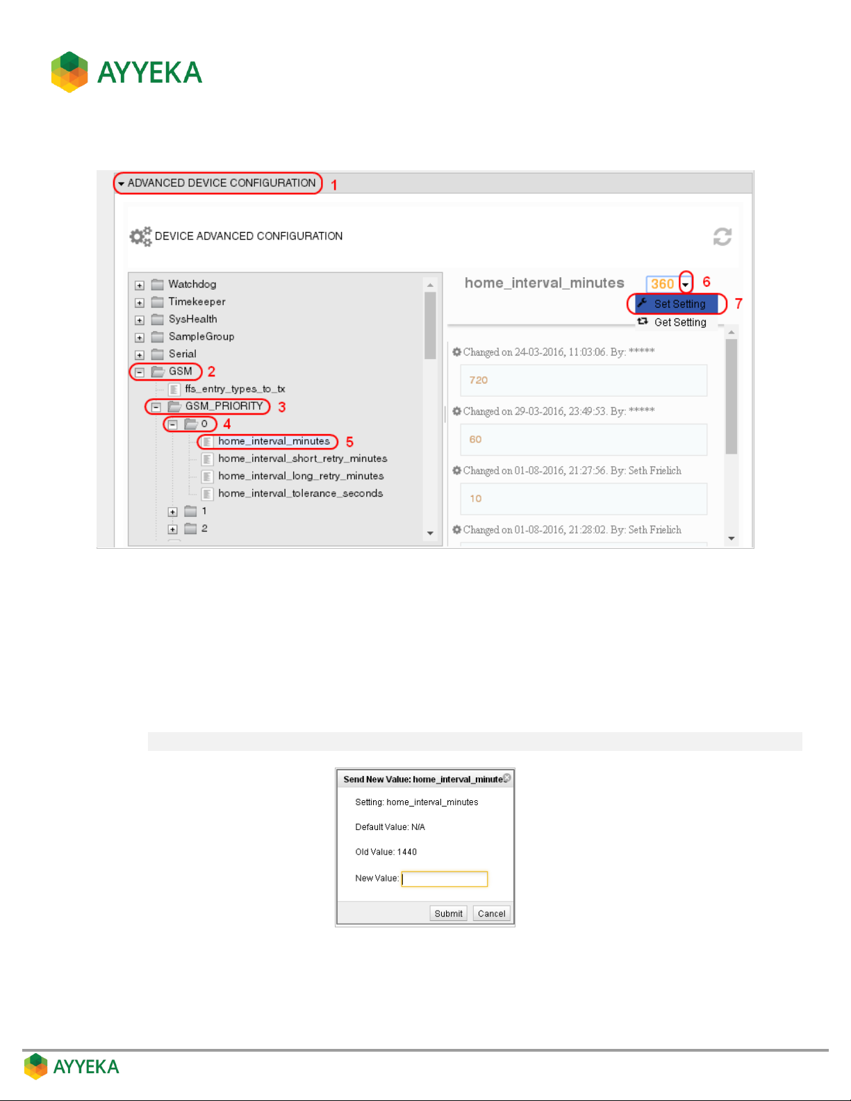
The device configuration tree is displayed.
Figure 27: Selecting the device transmission interval parameter
5. To change the device’s Normal transmission interval (in minutes), in the Device Configuration tree select
GSM > GSM_PRIORITY > 0 > home_interval_minutes and then:
a. To the right of the configuration tree, select the drop-down arrow adjacent to the current value.
b. Select Set Setting.
c. In the Send New Value window, enter the desired value in the New Value field, and click Submit.
Note: It is recommended not to set a value below 10 minutes, since this will drain the battery.
Figure 28: Send New Value window
6. To change the Event transmission interval (in minutes), select GSM > GSM_PRIORITY > 1 >
home_interval_minutes and follow the instructions in the sub-steps of step 5.
Page 42
7. To change the Emergency transmission interval (in minutes), select GSM > GSM_PRIORITY > 2 >
home_interval_minutes and follow the instructions in the sub-steps of step 5.
Setting the Device Sampling Interval
Sampling intervals are set at the stream level. For details, refer to Managing a Stream’s Sampling Interval.
Viewing the Files Sent and Received by the Device
To view the files sent and received by the device:
1. Click Devices in the sidebar.
2. In the Sites Tree pane, click the device name.
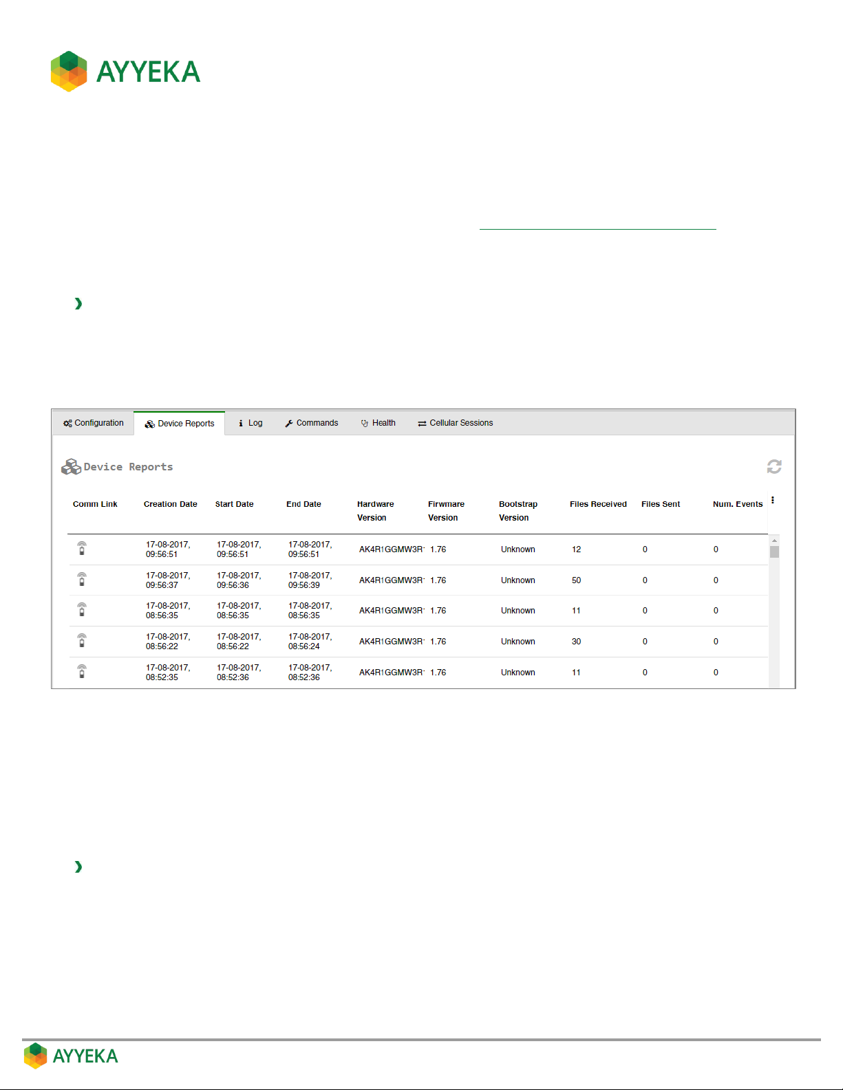
3. In the right pane, click the Device Reports tab.
Figure 29: Device – Device Reports tab
The report lists, for each event in which files were received from or sent by the device, the number of Files
Received from the device (such as files containing sensor readings), and Files Sent to the device (such as files
containing device configuration changes).
Viewing the Device Event Log
To view the device event log:
1. Click Devices in the sidebar.
2. In the Sites Tree pane, click the device name.
Page 43
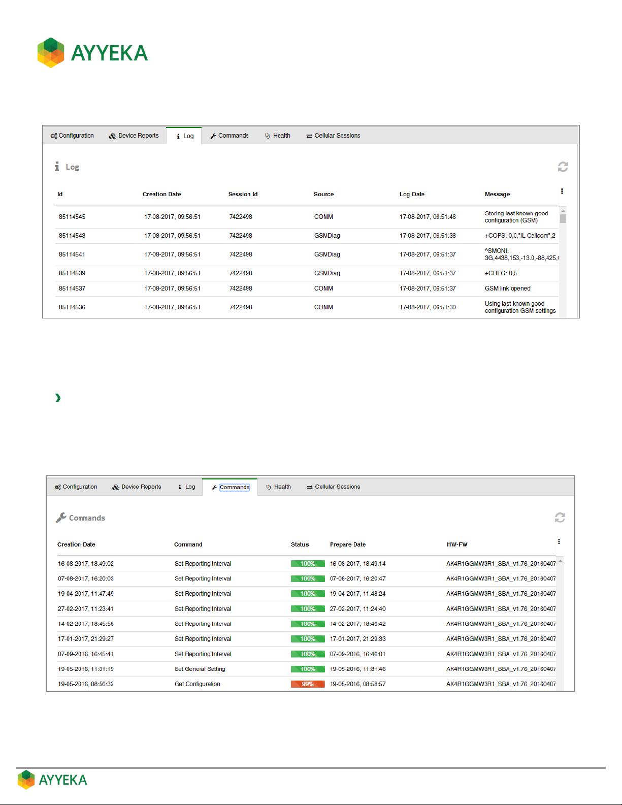
3. In the right pane, click the Log tab. The Log appears, listing all device activity.
Figure 30: Device – Log tab
Viewing the Commands Sent to the Device
To view the commands sent to the device:
1. Click Devices in the sidebar.
2. In the Sites Tree pane, click the device name.
3. In the right pane, click the Commands tab.
Figure 31: Device – Commands tab
The table lists all the commands sent to the device. These mainly include device configuration changes.
Page 44
Viewing the Health of the Device
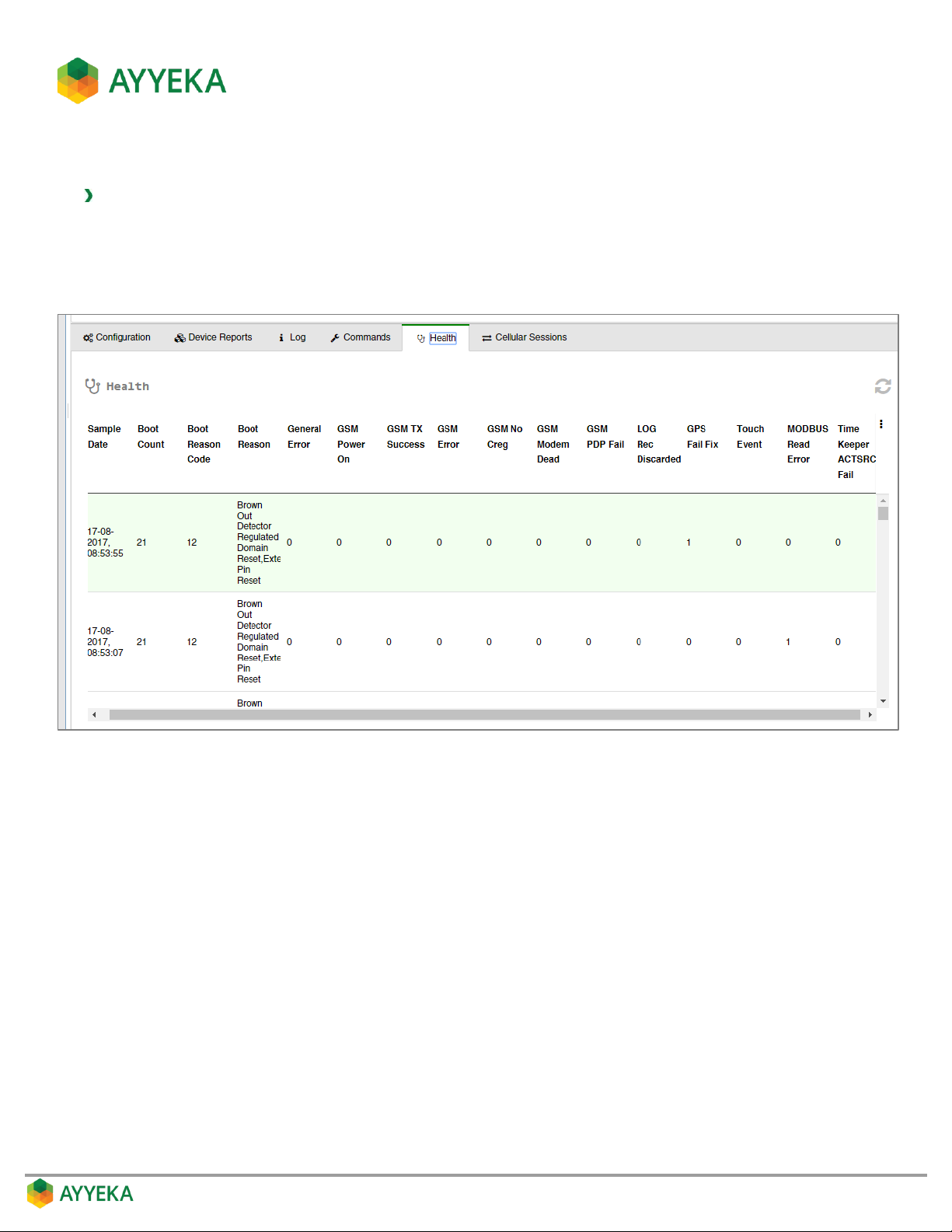
To view the health of the device:
1. Click Devices in the sidebar.
2. In the Sites Tree pane, click the device name.
3. In the right pane, click the Health tab.
Figure 32: Device – Health tab
This tab is intended for device troubleshooting, to help identify the possible source of issues.
Page 45
Viewing Device Cellular Information
To view the device cellular information:
1. Click Devices in the sidebar.
2. In the Sites Tree pane, click the device name.
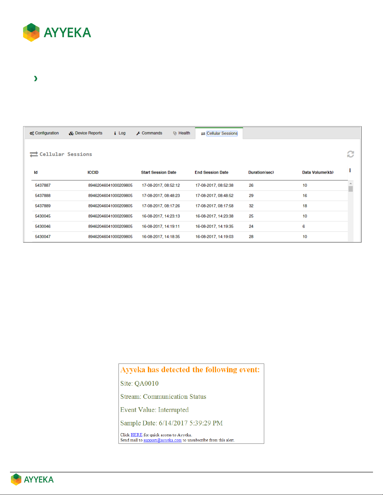
3. In the right pane, click the Cellular Sessions tab.
Figure 33: Device – Cellular Sessions tab
This tab lists information about each data transmission session during which the device transmitted data over the
mobile network.
Managing Device Technical Alerts
Account owners can set device technical alerts that will be sent as SMS and/or email messages if any device
crosses one of the following thresholds: communication-disruption, internal-humidity, or internal battery-level.
Note that device technical alerts are not sent immediately when the configured device thresholds are crossed.
Rather, they are sent once every 3 hours. However, each alert has a timestamp which identifies exactly when the
alert was triggered, as shown in the figure below.
Figure 34: Technical alert contents
Page 46
Viewing the List of Technical Alerts
To view all device technical alerts:
1. Click Devices in the sidebar.
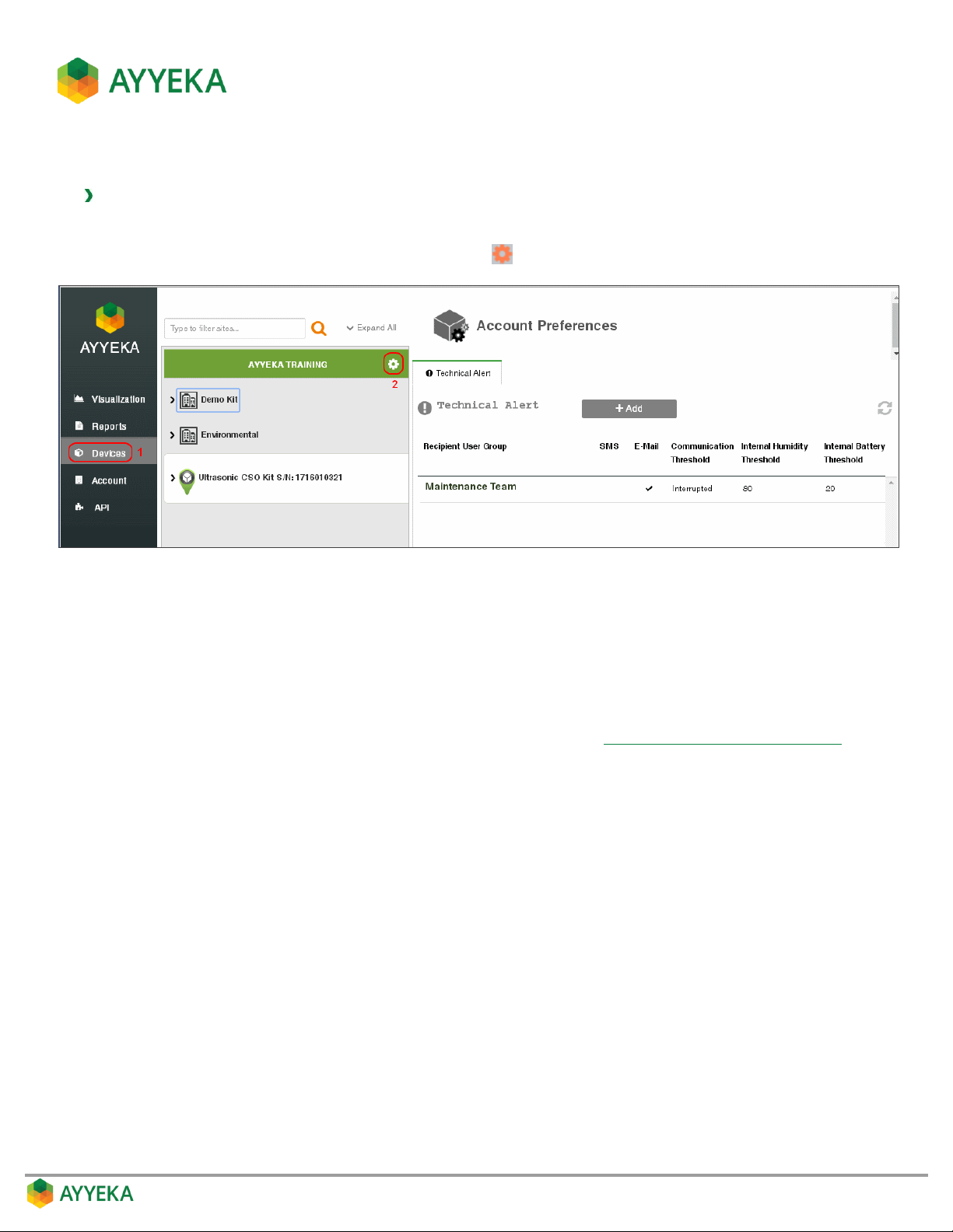
2. In the Sites Tree pane, click the Preferences icon adjacent to the account name.
Figure 35: Selecting Account Preferences
3. View the technical alerts listed in the Technical Alert table. The table shows, for each technical alert:
Whether the alert is sent in an SMS text message and/or in an email.
Whether an alert is sent when communication is Delayed or Interrupted beyond a certain
threshold. An empty cell indicates that no alert is sent if communications are delayed or interrupted.
Please note: Each device has its own Delayed Transmission and Interrupted Transmission
thresholds, which are set at the device level, as described in Setting the Device Reporting Profile.
The internal humidity threshold. If the internal humidity level in the device rises to above this
threshold, a humidity threshold alert will be sent. An empty cell indicates that no alert is sent for
humidity levels.
The internal battery threshold. If the internal battery level falls to below this threshold, a battery
threshold alert will be sent. An empty cell indicates that no alert is sent for battery levels.
Page 47
Adding a Technical Alert
To add a device technical alert:
1. Click Devices in the sidebar.
2. In the Sites Tree pane, click the Preferences icon adjacent to the account name.
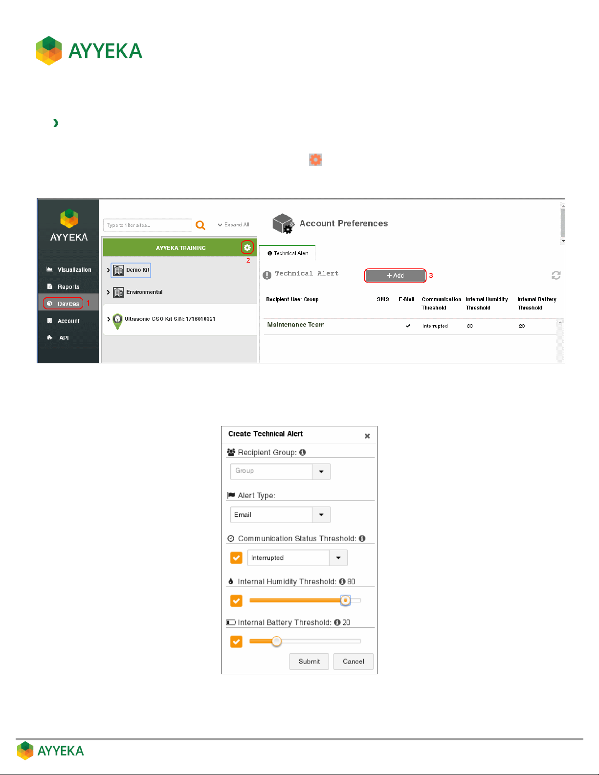
3. Click + Add.
Figure 36: Selecting to Add a Technical Alert
The Create Technical Alert window appears:
Figure 37: Creating a technical alert
Page 48

4. In the Create Technical Alert window:
a. Select a Recipient Group. All members of the group you specify will receive the alert. Note that you
need to first define a user group, as described in Managing User Groups.
b. Select the Alert Type: Email, SMS, or Email & SMS.
c. In Communication Status Threshold:
Check the Communication Status Threshold box if you wish to send an alert upon a
communication status threshold being crossed.
Select whether to send an alert when communication status is Delayed or Interrupted beyond
the configured threshold. Note that each device has its own Delayed Transmission and
Interrupted Transmission thresholds, set at the device level. You can view and set these
thresholds as described in Setting the Device Reporting Profile.
d. In Internal Humidity Threshold:
Check the Internal Humidity Threshold box if you wish to send an alert upon an internal
device humidity threshold being crossed.
Use the slider to set the upper humidity threshold (in percentage of humidity). If the internal
humidity level rises to above the threshold, a humidity threshold alert will be sent.
e. In Internal Battery Threshold:
Check the Internal Battery Threshold box if you wish to send an alert upon an internal battery
threshold being crossed.
Use the slider to set the lower battery threshold (in percentage of battery power remaining). If
the internal battery level falls to below the threshold, a battery threshold alert will be sent.
f. Click Submit.
Page 49
Editing, Deactivating, Reactivating or Deleting a Technical Alert
To edit, deactivate, reactivate or delete a device technical alert:
1. Click Devices in the sidebar.
2. In the Sites Tree pane, click the Preferences icon adjacent to the account name.
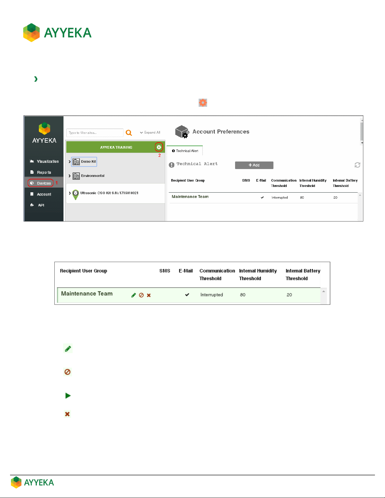
Figure 38: Technical Alerts table
3. Hover over the line corresponding to the technical alert you wish to modify. Several icons appear.
Figure 39: Options for modifying a technical alert
4. Select the icon corresponding to the action you wish to take:
Edit technical alert settings. Click this icon and edit the settings in the window
that appears.
Deactivate the technical alert. A deactivated technical alert does not trigger any
alerts, but is not deleted from the database.
Reactivate the technical alert.
Delete the technical alert from the database.
Page 50
Setting the Device Reporting Profile
Each device has its own Delayed Transmission and Interrupted Transmission thresholds, which are set at the
device level. These thresholds determine, in cases where device transmission problems occur, at what point a
device transmission alert is sent (assuming a Device Technical Alert was defined). An account and organization
owner or administrator can view and set these thresholds, which are called the device reporting profile.
To view or change a device reporting profile:
1. Click Devices in the sidebar
2. Select the device in the Sites Tree pane.
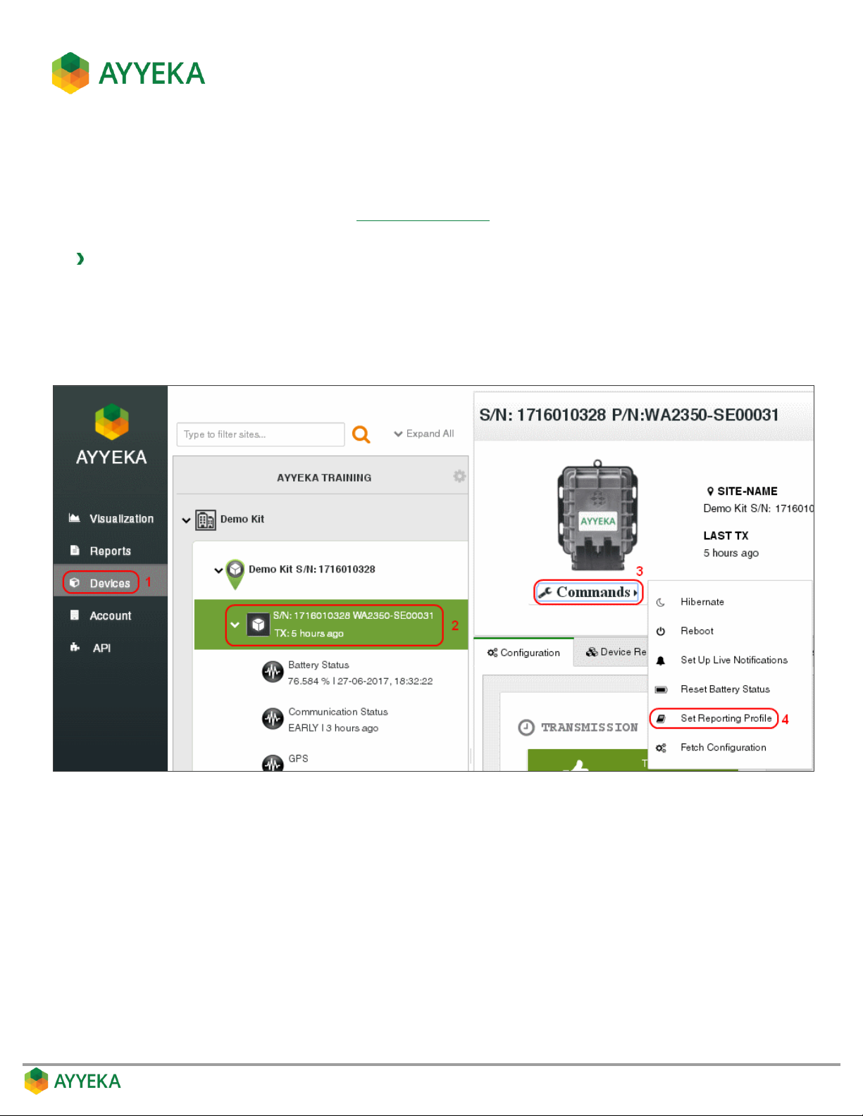
3. In the bottom part of the device information box, click the arrow in the drop-down Commands list, and
select Set Reporting Profile.
Figure 40: Selecting to set reporting profile
Page 51
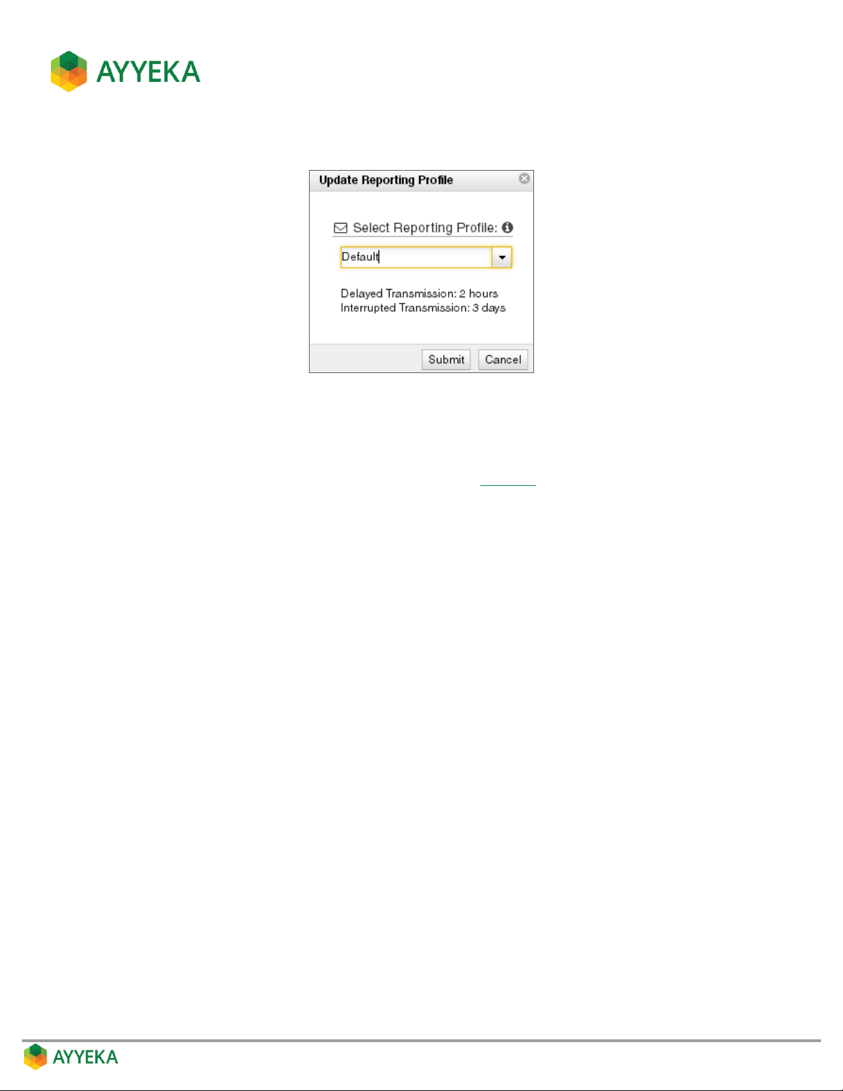
The Update Reporting Profile window appears.
Figure 41: Setting the device reporting profile
4. In the Update Reporting Profile window, select a device Reporting Profile from the drop-down list. Each
profile defines a specific threshold for Delayed Transmission and for Interrupted Transmission.
For example, if you select the Default profile (shown in Figure 41), then if device transmission is delayed
for over 2 hours relative to its expected transmission schedule, a Delayed Transmission alert is sent;
and if the device fails to transmit for over 3 consecutive days relative to its expected transmission
schedule, it is considered to be in an Interrupted Transmission state, and an Interrupted Transmission
alert is sent.
Page 52
Setting Up Live Notifications
You can use the Live Notifications option to send to your mobile phone all the messages a device transmits. This is
mainly intended for use during initial device installation, or troubleshooting in the field. Typically, you would set up
Live Notifications before re-activating the device with the magnetic activator, so as to easily view in real time all
device transmissions such as sensor readings, GSM values, GPS values, etc.
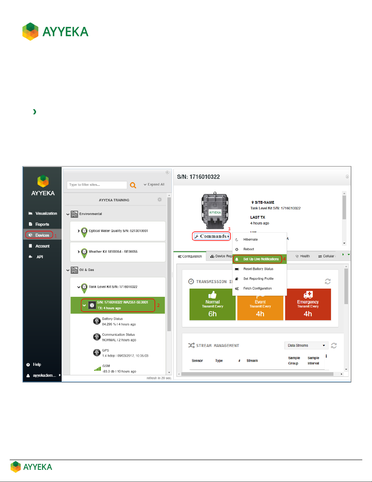
To set up live notifications:
1. Click Devices in the sidebar
2. Select the device in the Sites Tree pane.
3. In the bottom part of the device information box, click the arrow in the drop-down Commands list, and
select Set Up Live Notifications.
Figure 42: Selecting to Set Up Live Notifications
Page 53
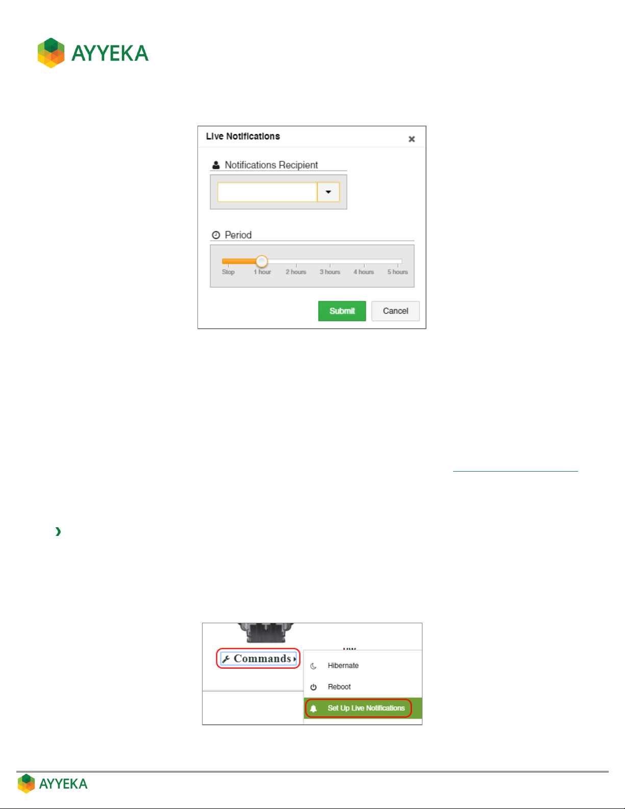
The Live Notifications window appears.
Figure 43: Setting up Live Notifications
4. In the Live Notifications window:
a. Specify which user will receive live notifications from the device. The live notifications will be sent as
SMS messages to the recipient’s mobile phone.
b. Specify the duration of the period when live notifications are sent to the recipient. The period starts
from the moment you click Submit. Thus, if you specified a duration period of 2 hours, and clicked
Submit at 8 AM, then live notifications will be sent from 8 AM to 10 AM. Note that you can cancel
Live Notifications before the duration period has ended, as described in Cancelling Live Notifications.
c. Click Submit.
Cancelling Live Notifications
To cancel live notifications:
1. Click Devices in the sidebar
2. Select the device in the Sites Tree pane.
3. In the bottom part of the device information box, click the arrow in the drop-down Commands list, and
select Set Up Live Notifications.
4. In the Live Notifications window that appears:
Page 54
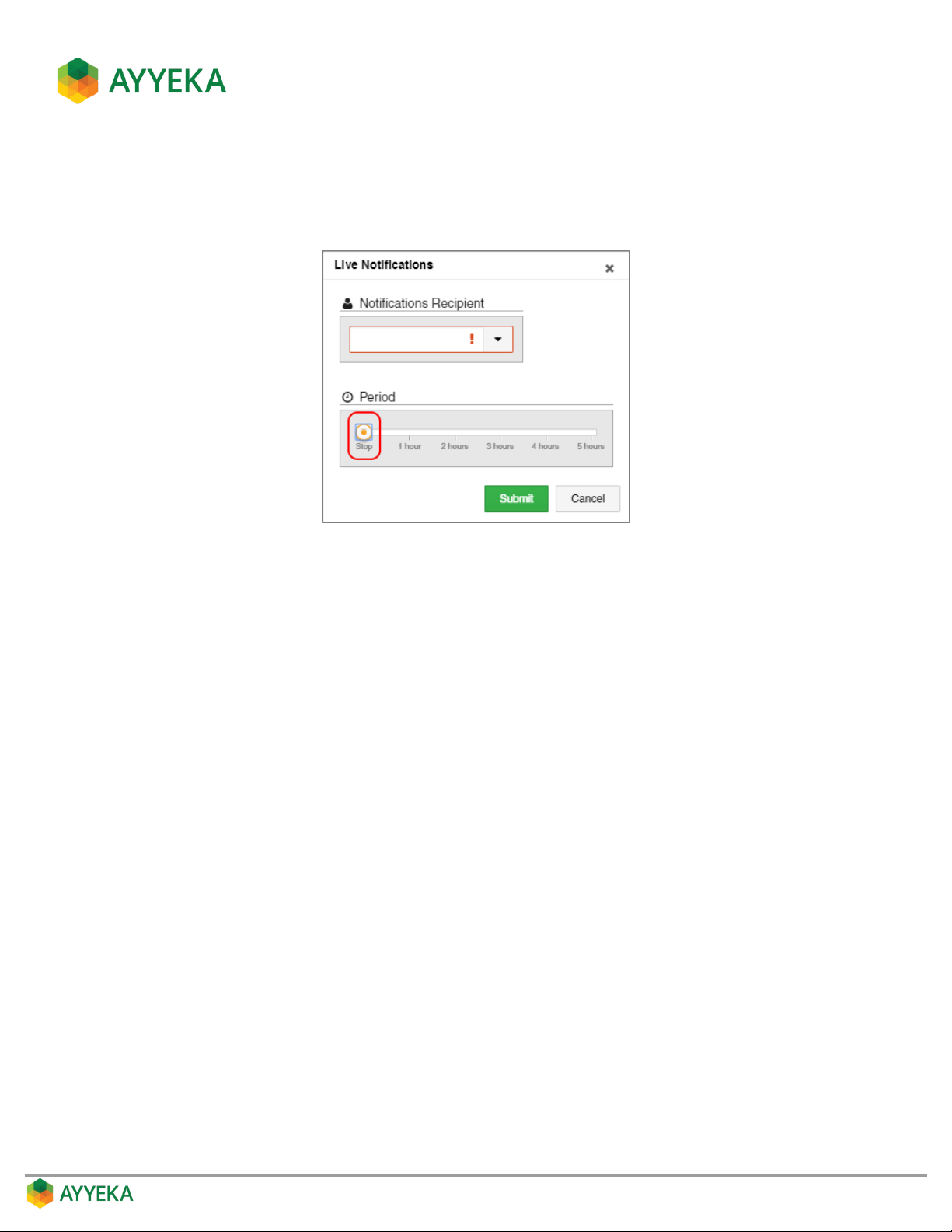
a. Specify the user for whom you wish to cancel Live Notifications.
b. Set the Period to Stop.
c. Click Submit.
Figure 44: Selecting to Stop Live Notifications
Page 55
MANAGING DATA STREAMS
Each data stream shows the actual data received from a specific sensor connected to a specific Wavelet device.
Viewing a Data Stream
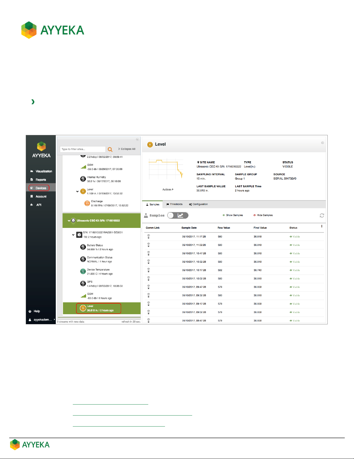
To view data stream information:
1. Click Devices in the sidebar.
2. In the Sites Tree pane, click the data stream name.
Figure 45: Selecting a data stream
Data stream information appears in the right pane. This includes:
The stream’s name, the site’s name, the stream’s type, sampling interval, status, source, last sample
time, and last sample value.
A graph depicting the samples’ trend in the past 48 hours.
Three tabs, enabling:
Viewing and Filtering Samples
Viewing and Editing the Treatment of Raw Data
Configuring Data Stream Thresholds
Page 56
Editing a Data Stream
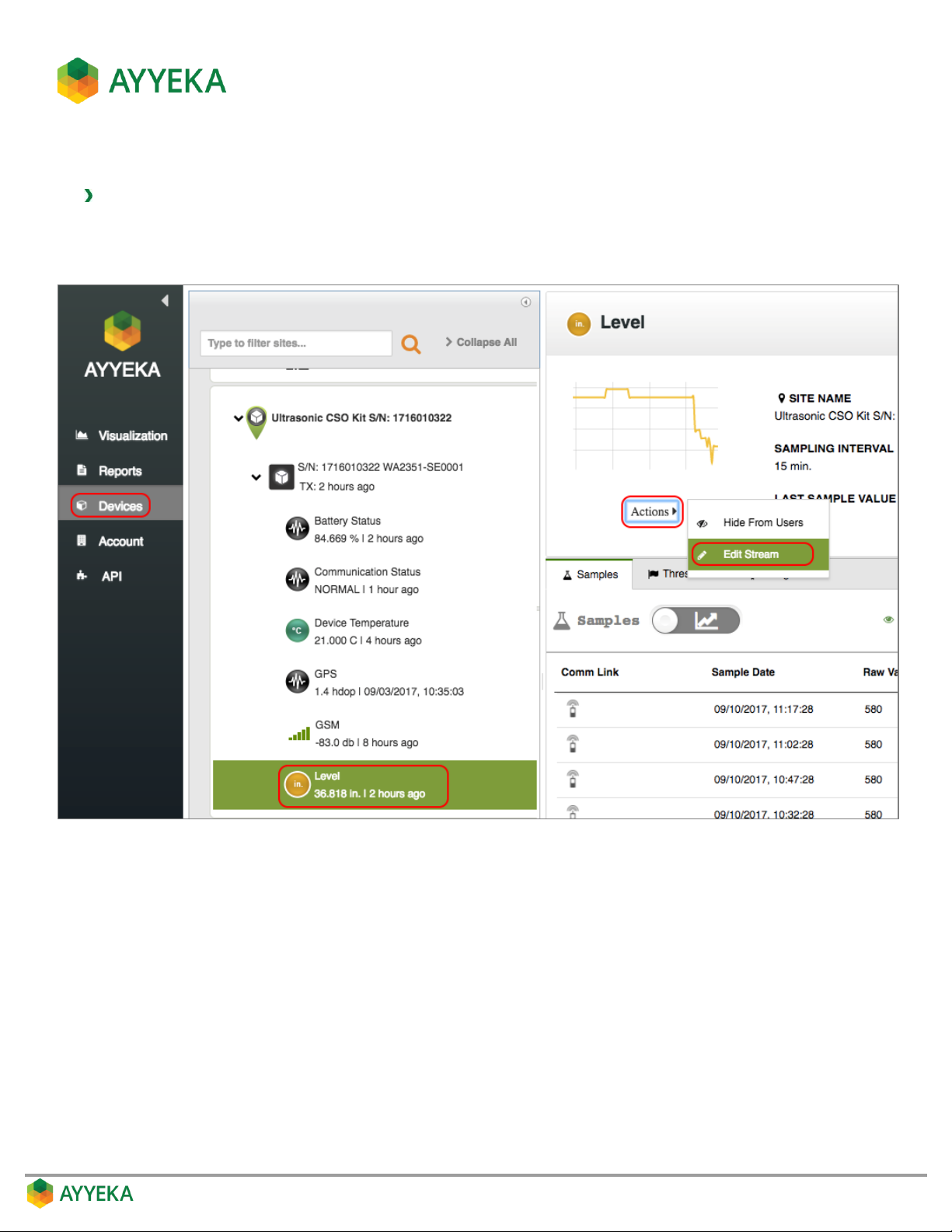
To edit a stream’s settings:
1. Click Devices in the sidebar, and click the stream name in the Sites Tree pane.
2. In the right pane, click Actions underneath the graph, and select Edit Stream.
Figure 46: Selecting to edit a data stream
Page 57
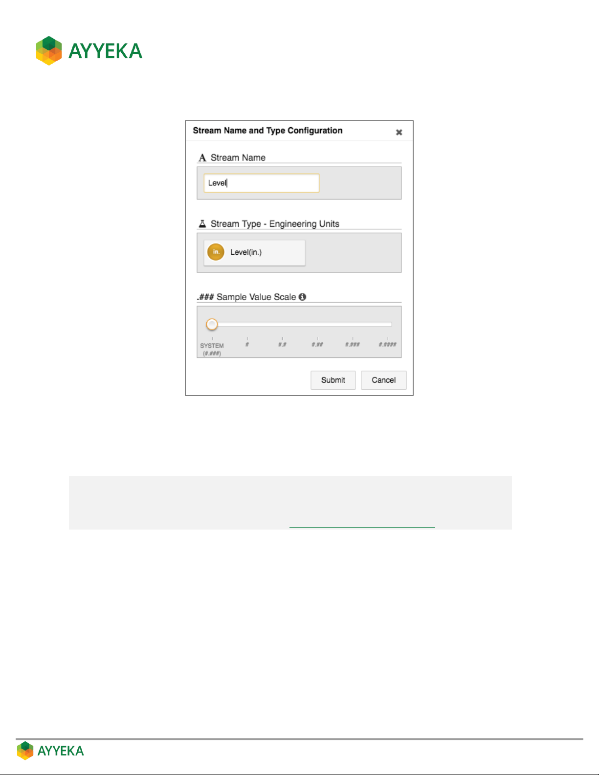
The Stream Name and Type Configuration window appears.
Figure 47: Changing stream settings
3. Optionally change the Stream Name.
4. Optionally change the Engineering Units that appear in the Sites Tree pane and in reports.
Note: Keep in mind that if you want the final values (derived by converting the raw value
into engineering units) to be correctly expressed in a specific engineering unit (for
example in inches rather than feet), you need to edit the formula for converting raw
data into engineering units. Refer to Changing the Conversion Formula.
5. Optionally change the Sample Value Scale, which specifies how many decimal points to display after a
whole value. This enables you to set the level of accuracy when displaying values in the Sites Tree pane
and in generated reports.
6. Click Submit.
Page 58
Hiding a Data Stream
An account owner can hide a stream from other account users. A hidden stream is only visible to account owners.
At any time, the account owner can un-hide a hidden stream and make it visible again to all account users.
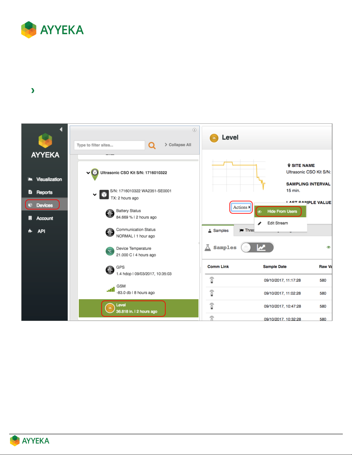
To hide a stream:
1. Click Devices in the sidebar, and click the stream name in the Sites Tree pane.
2. In the right pane, click Actions underneath the graph, and select Hide from Users.
Figure 48: Selecting to Hide a Stream
A confirmation window appears.
Page 59
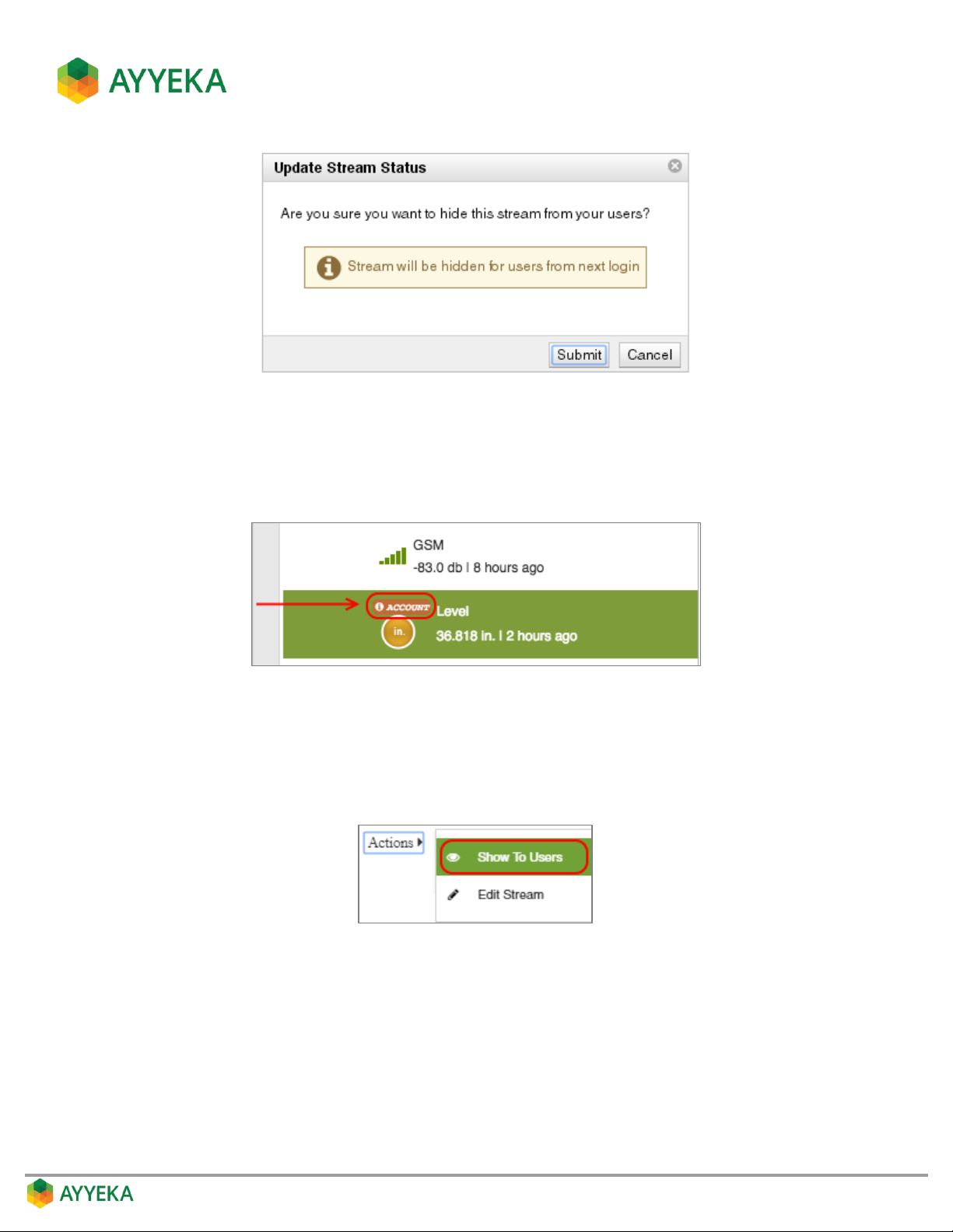
Figure 49: Confirm hiding a stream
3. Click Submit.
An indication appears, adjacent to the stream name, indicating the stream will be hidden from other
account user from their next login, and will be visible to the account owner(s) only.
Figure 50: Indication of a hidden stream
4. To un-hide a stream:
a. Click Devices in the sidebar, and click the stream name in the Sites Tree pane.
b. In the right pane, click Actions underneath the graph, and select Show To Users.
The stream will now be visible to all account users from their next login.
Page 60
Viewing and Filtering Samples
You can view the samples taken by a specific sensor.
To view samples:
1. Click Devices in the sidebar, and click the stream name in the Sites Tree pane.
2. In the right pane, select the Samples tab.
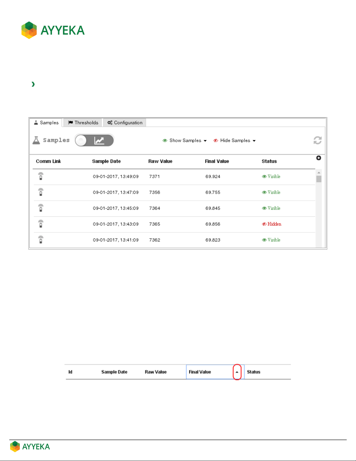
Figure 51: Samples table
The samples table shows, for each reading taken in the past:
The sampling date and time
The raw value
The final value after converting the raw value to engineering units
The Hidden/Visible status of the sample
Sorting the Samples table
You can sort the entries in the table by a specific column. To do so, click the column head and then click the arrow
appearing to the right. The samples are sorted in descending order. Click again to sort by ascending order.
Page 61
Hiding Samples in the Samples table
You may wish to change the status of some samples to Hidden, for example because you know they do not
represent the true state of the body being sampled. Hidden samples appear neither in the Visualization window
nor in reports.
Hiding a single sample
To hide a single sample:
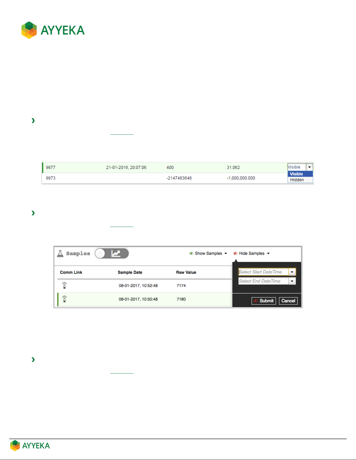
1. In the samples table (Figure 51), double-click the word Visible in the line corresponding to the data point
you wish to hide.
2. In the dropdown menu, select Hidden.
Hiding samples from an entire period
To hide samples from a certain period:
1. In the samples table (Figure 51), select Hide Samples.
2. In the dropdown menu, enter the start and end dates, and click Submit.
Figure 52: Hiding samples
The status of all samples from the specified period changes to Hidden.
Filtering the Samples table
To display samples only from a certain period:
1. In the samples table (Figure 51), select Show Samples.
2. In the dropdown menu, enter the start and end dates, and click Submit.
Only samples from the specific period are displayed in the table.
Page 62
Configuring Data Stream Thresholds
A key feature of the Ayyeka system is the ability to configure multiple thresholds for any data stream, and specify
actions such as alerts when data samples cross a threshold.
Thresholds are configured using ranges of values bound by a lower and upper limit. Let’s say you want to
configure thresholds for a Temperature data stream. You can define a Low threshold of 0-40°F, a Normal
threshold of 40-120°F, and a High threshold of 120-250°F. For each threshold range, you can configure Actions
the Wavelet device should perform when data samples cross into a threshold range, such as modifying the
sampling or transmission frequency, or sending email and/or SMS alerts to certain users.
Accessing the threshold view
In a nutshell:
1. Click Devices in the sidebar.
2. In the Sites Tree pane select the stream.
3. In the right pane select the Thresholds tab.
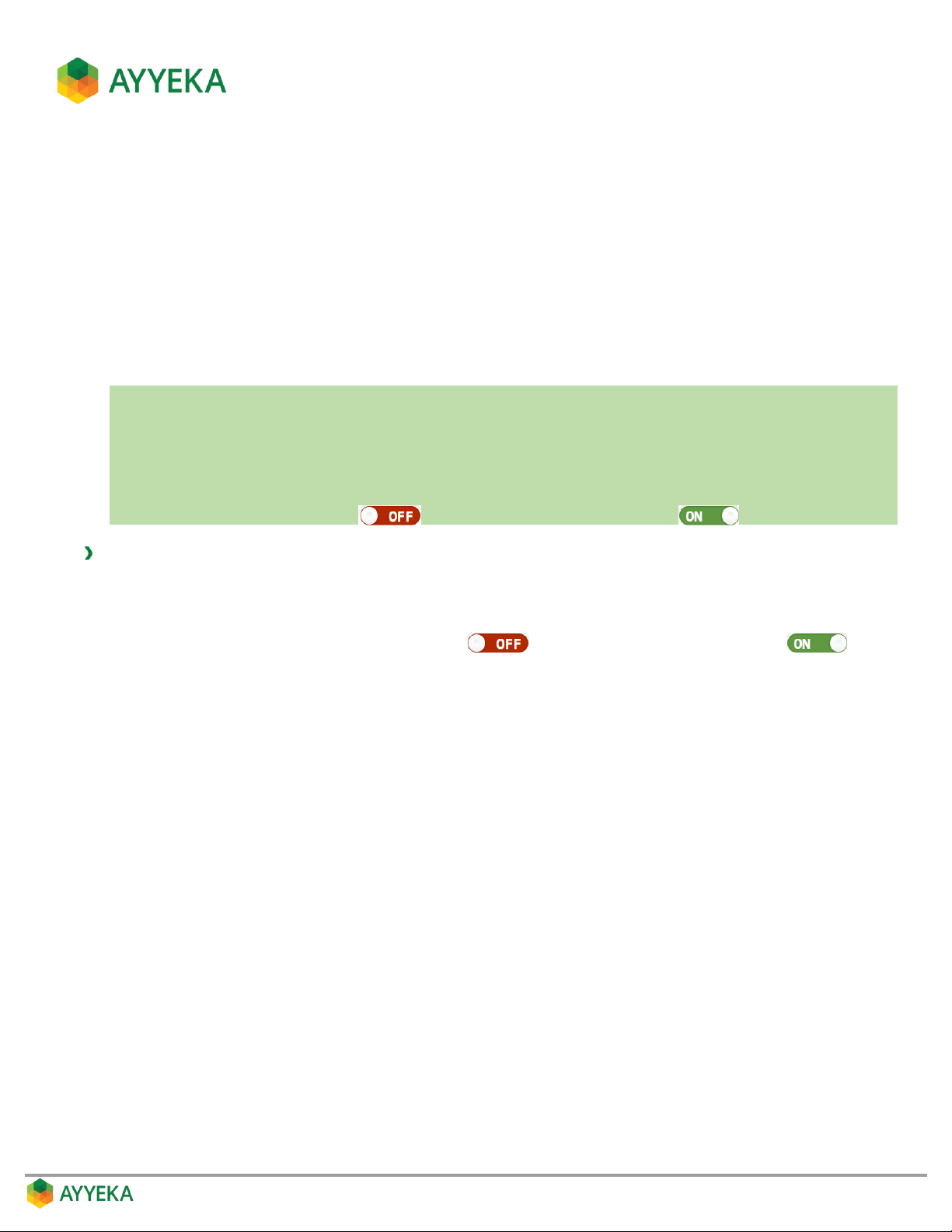
4. If the Thresholds slider is OFF , click it to switch Thresholds to ON .
To view or set a data stream’s thresholds:
1. Click Devices in the sidebar, and click the stream name in the Sites Tree pane.
2. In the right pane, select the Thresholds tab.
3. If the Thresholds slider is in the OFF position , click it to switch Thresholds to ON .
A graph appears, showing the data stream values for the past week (use the Time Frame slider to zoom in
or out).
The thresholds defined for this data stream are displayed below the graph.
By default, the system creates three ranges for each data stream: Low, Normal and High.
The thresholds cover the entire spectrum of actual stream values collected by the device.
Page 63
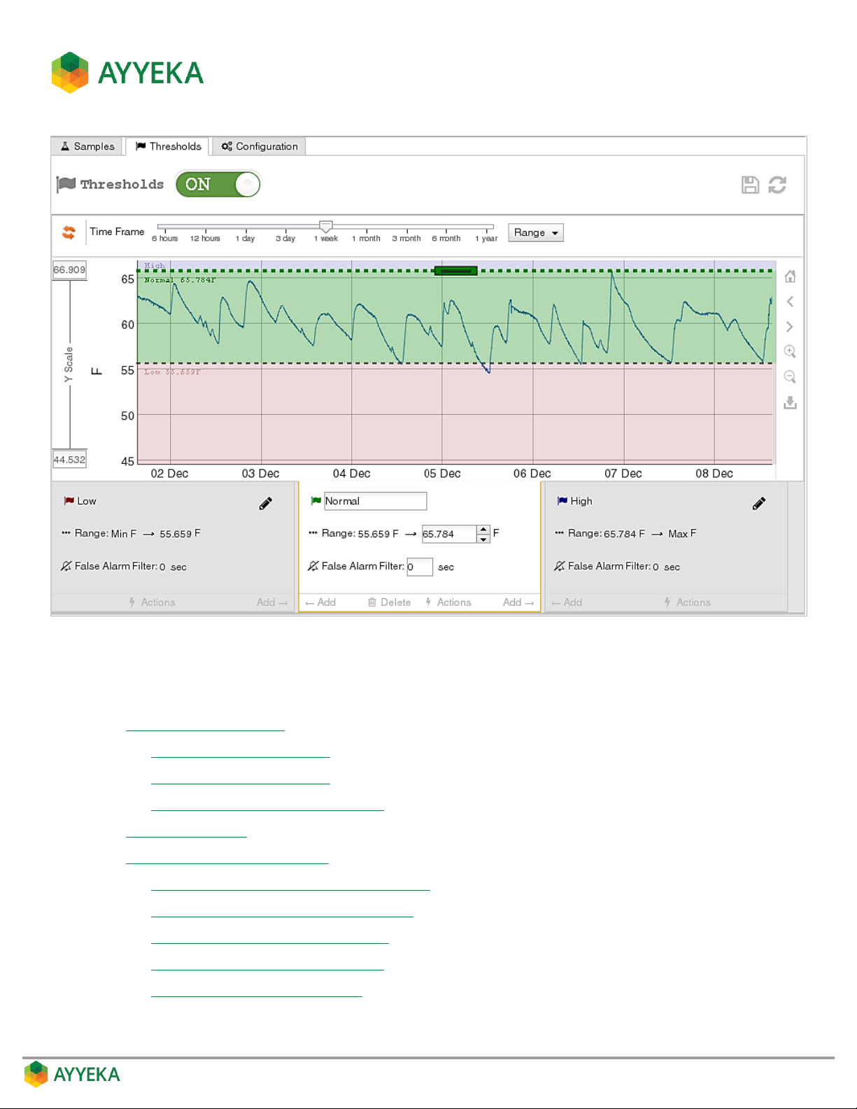
Figure 53: Thresholds view
You can:
Change threshold settings by:
Changing a threshold’s name
Changing a threshold’s range
Setting a threshold’s False Alarm Filter
Add new thresholds
View or change threshold actions, such as:
Setting whether to transmit data immediately
Setting a Threshold’s Transmission Interval
Setting a Threshold’s Sampling Interval
Defining a Threshold’s Alert Recipients
Setting Resultant Sampling Actions
Page 64
Note: All threshold configuration changes will take effect after the device next
communicates with the server.
Changing threshold settings
You can change the following threshold settings:
Changing a threshold’s name
Changing a threshold’s range
Setting a threshold’s False Alarm Filter
Changing a threshold’s name
In a nutshell:
1. Click Devices in the sidebar.
2. In the Sites Tree pane select the stream.
3. In the right pane select the Thresholds tab.
4. If the Thresholds slider is OFF , click it to switch Thresholds to ON .
5. In the threshold definition area, click the current name, adjacent to the flag, and overwrite it with the
new name.
6. Save changes by clicking .
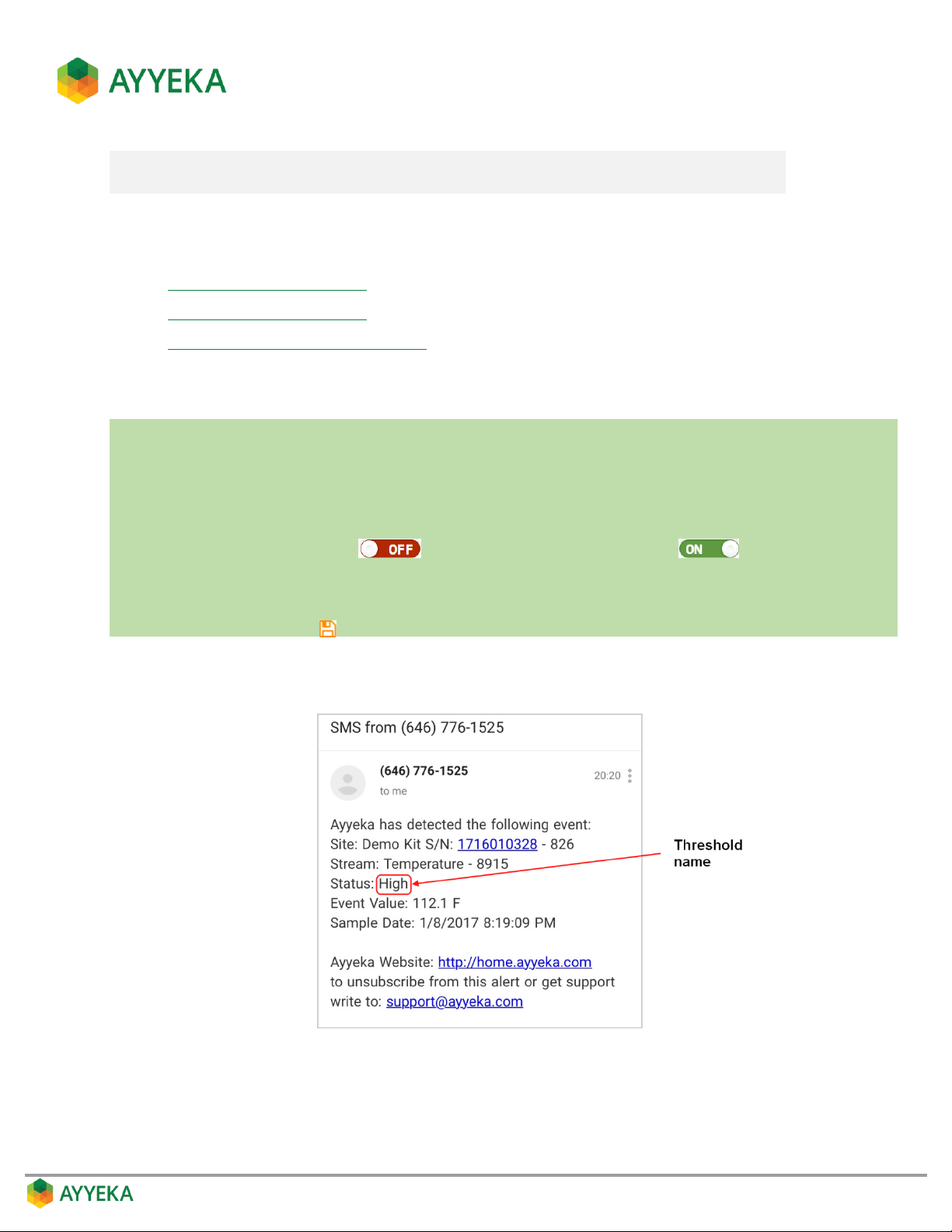
It is recommended to give each threshold an appropriately descriptive name because in the threshold alert text,
the threshold name is the only indication of the reason why the alert was sent, as shown below.
Figure 54: Example alert text
Page 65
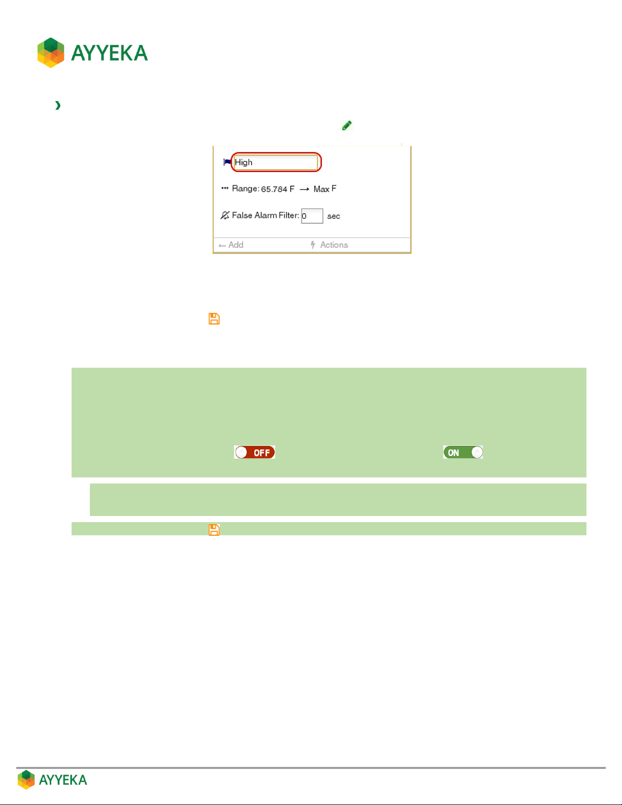
To change a threshold’s name:
1. In the threshold definition area, click the pencil icon .
Figure 55: Threshold definition area
2. Overwrite the current name with the new name.
3. Save changes by clicking .
Changing a threshold’s range
In a nutshell:
1. Click Devices in the sidebar.
2. In the Sites Tree pane select the stream.
3. In the right pane select the Thresholds tab.
4. If the Thresholds slider is OFF , click it to switch Thresholds to ON .
5. In the threshold definition area:
a. Set the threshold’s upper limit by editing it directly.
b. Set the threshold’s lower limit by editing the upper limit of the threshold to its left.
6. Save changes by clicking .
The thresholds mechanism works as follows:
Thresholds cover the entire spectrum of actual stream values collected by the device.
Thresholds are organized in ascending order, from the lowest (left-most), to the highest (right-most).
Only a threshold’s upper limit is editable. A given threshold’s lower limit is the upper limit of the
preceding threshold.
The lower limit of the lowest (left-most) threshold is not-editable, and is set by the system depending on
the given stream’s lowest value.
The upper limit of the highest (right-most) threshold is not-editable, and is set by the system depending
on the given stream’s highest value
Page 66
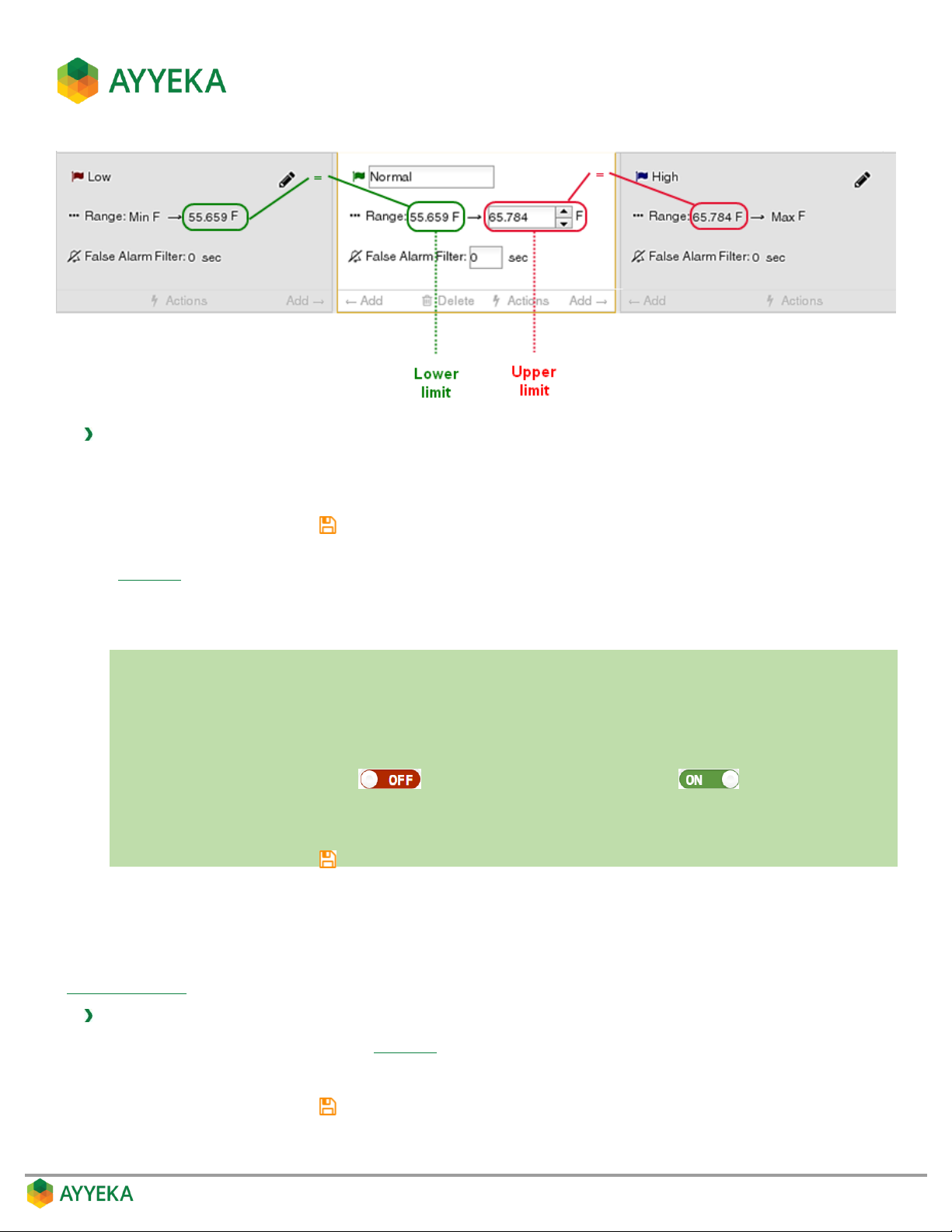
Therefore, to set a threshold’s range of values:
1. Set the threshold’s upper limit by editing it directly.
2. Set the threshold’s lower limit by editing the upper limit of the threshold to its left.
3. Save changes by clicking .
Alternatively, you can drag the dotted lines, representing the thresholds’ upper and lower limits, in the threshold
graph (Figure 53). The ranges of the relevant thresholds are updated accordingly.
Setting a threshold’s False Alarm Filter
In a nutshell:
1. Click Devices in the sidebar.
2. In the Sites Tree pane select the stream.
3. In the right pane select the Thresholds tab.
4. If the Thresholds slider is OFF , click it to switch Thresholds to ON .
5. In the threshold definition area, click the value of the False Alarm Filter, and overwrite it with the new
value.
6. Save changes by clicking .
The false alarm filter is intended to help ensure that threshold alerts are not sent for very short data spikes. For
example, if you set this value to 120 seconds, that means no threshold alerts will be sent if stream samples are
within the threshold for less than 2 minutes.
Note that in order for the false alarm filter to be meaningful, its value should be set no higher than the threshold’s
Sampling Interval.
To set a threshold’s false alarm filter:
1. In the threshold definition area (Figure 55), click the value adjacent to False Alarm Filter.
2. Overwrite the current value with the new value.
3. Save changes by clicking .
Page 67
Adding a new threshold
In a nutshell:
1. Click Devices in the sidebar.
2. In the Sites Tree pane select the stream.
3. In the right pane select the Thresholds tab.
4. If the Thresholds slider is OFF , click it to switch Thresholds to ON .
5. In the threshold definition area:
c. Click or to add a threshold before (to the left of) or after (to the right of) an existing
threshold.
d. Edit the threshold as desired. Refer to:
Changing a threshold’s name
Changing a threshold’s range
Setting a threshold’s False Alarm Filter
Setting Threshold Actions
6. Save changes by clicking .
You can define more thresholds in addition to the three thresholds the system creates by default. A new threshold
is always inserted in between two existing thresholds. It can be inserted anywhere between the very lowest and
very highest thresholds. The maximum number of thresholds for a data stream is eight thresholds.
To add a new threshold:
1. Determine where you want to insert the new threshold, and then in the threshold definition area
(Figure 55) click either or to add a threshold before (to the left of) or after (to the right
of) an existing threshold.
2. Edit the threshold as desired. Refer to:
Changing a threshold’s name
Changing a threshold’s range
Setting a threshold’s False Alarm Filter
Setting Threshold Actions
3. Save changes by clicking . The changes will go into effect the next time the device communicates with
the server.
Page 68
Setting Threshold Actions
In a nutshell:
1. Click Devices in the sidebar.
2. In the Sites Tree pane select the stream.
3. In the right pane select the Thresholds tab.
4. If the Thresholds slider is OFF , click it to switch Thresholds to ON .
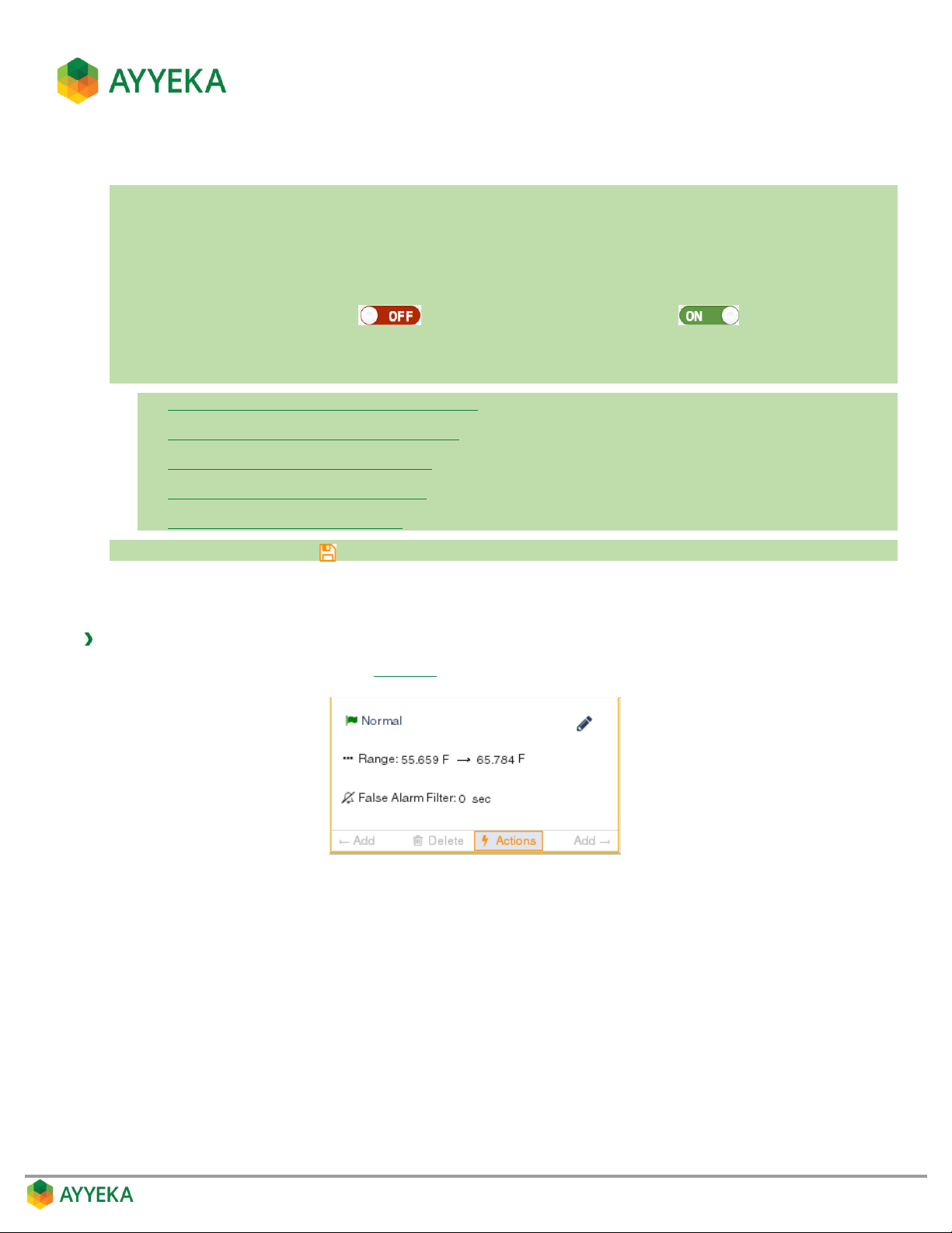
5. In the threshold definition area, click Actions.
6. In the Threshold actions window, set any of the following:
Setting whether to transmit data immediately
Setting a Threshold’s Transmission Interval
Setting a Threshold’s Sampling Interval
Defining a Threshold’s Alert Recipients
Setting Resultant Sampling Actions
7. Save changes by clicking .
For each threshold, you can define what actions the device should take when stream samples fall within the range
of the threshold.
To set threshold actions:
1. In the threshold definition area (Figure 55), click Actions.
Page 69
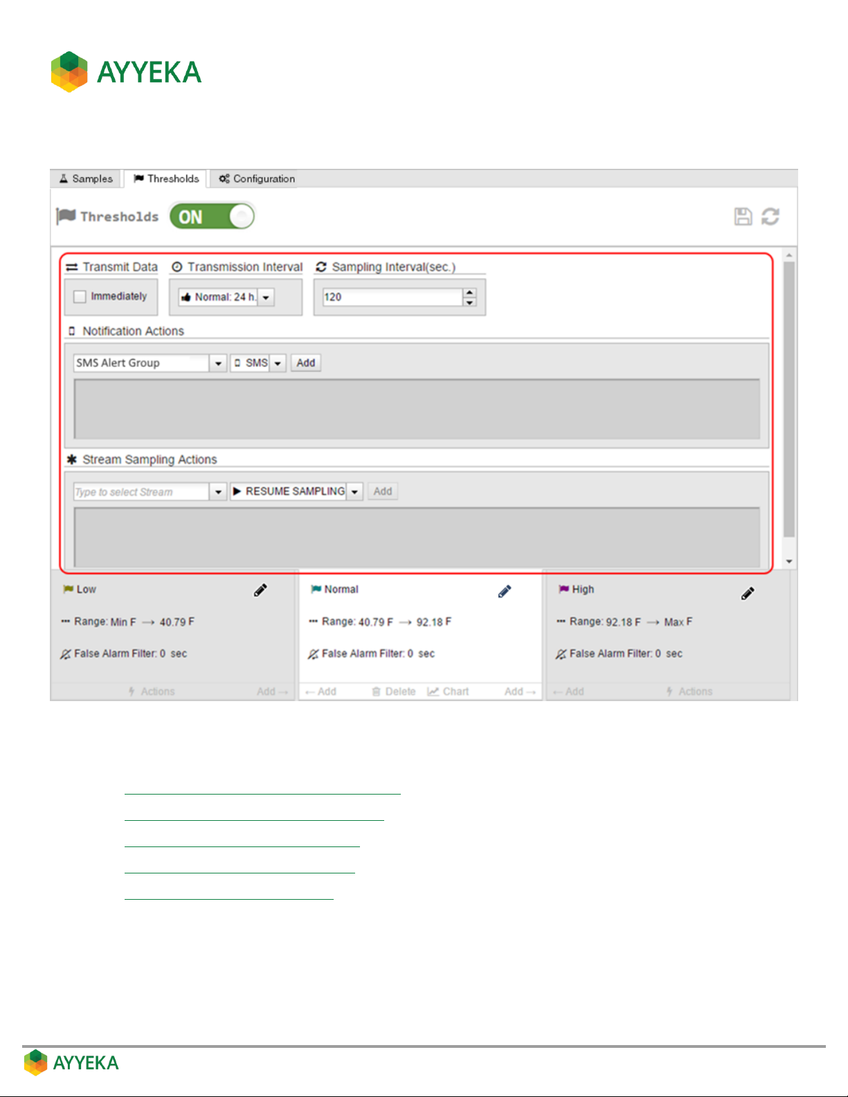
The thresholds actions view is displayed.
Figure 56: Threshold Actions view
In the Threshold actions window, you can set any of the following:
Setting whether to transmit data immediately
Setting a Threshold’s Transmission Interval
Setting a Threshold’s Sampling Interval
Defining a Threshold’s Alert Recipients
Setting Resultant Sampling Actions
Page 70
Setting whether to transmit data immediately
In a nutshell:
1. Click Devices in the sidebar.
2. In the Sites Tree pane select the stream.
3. In the right pane select the Thresholds tab.
4. If the Thresholds slider is OFF , click it to switch Thresholds to ON .
5. In the threshold definition area, click Actions.
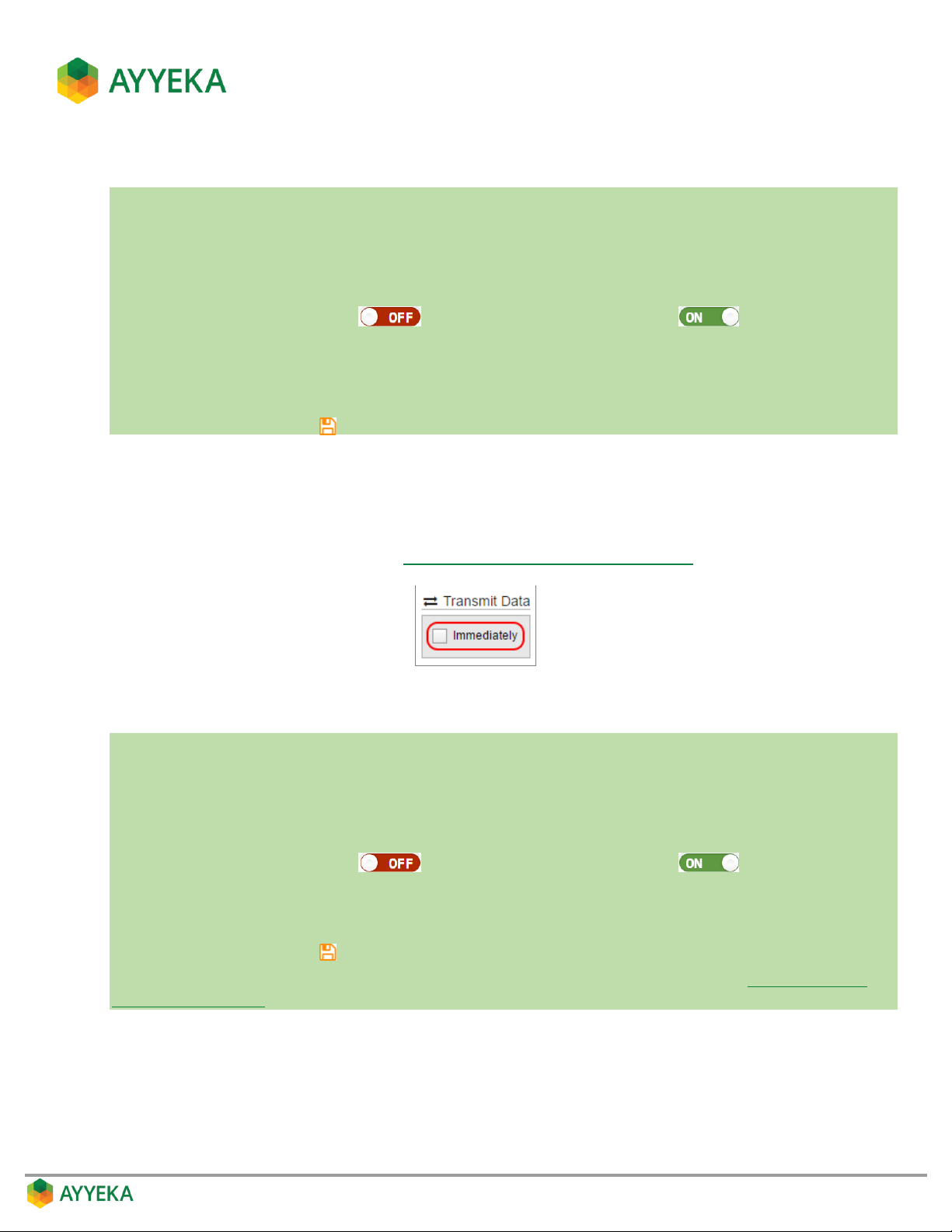
6. Under Transmit Data, check the Immediately box if you want the device to transmit data immediately
when a stream sample crosses into this threshold.
7. Save changes by clicking .
In the Transmit Data section, specify whether the device should transmit data immediately when a stream
sample crosses into this threshold, or whether the device should wait until the next scheduled transmission
time.
Note that the system automatically checks the Immediately box if you specify that users should be notified
when samples enter the threshold range (see Defining a Threshold’s Alert Recipients).
Setting a Threshold’s Transmission Interval
In a nutshell:
1. Click Devices in the sidebar.
2. In the Sites Tree pane select the stream.
3. In the right pane select the Thresholds tab.
4. If the Thresholds slider is OFF , click it to switch Thresholds to ON .
5. In the threshold definition area, click Actions.
6. Under Transmission Interval, select either Normal, Event or Emergency.
7. Save changes by clicking .
To change the Normal, Event and Emergency transmission intervals of a device, refer to Setting the Device
Transmission Intervals.
A transmission interval defines how often the device transmits data gathered by its sensors.
Every device has three configurable transmission intervals: Normal, Event and Emergency. Transmission
interval Normal is the default interval. Transmission intervals Event and Emergency are two alternate
intervals. Data is always transmitted at the Normal rate, unless a different rate is specified– either Event or
Emergency – when stream samples fall within a certain threshold range.
Page 71
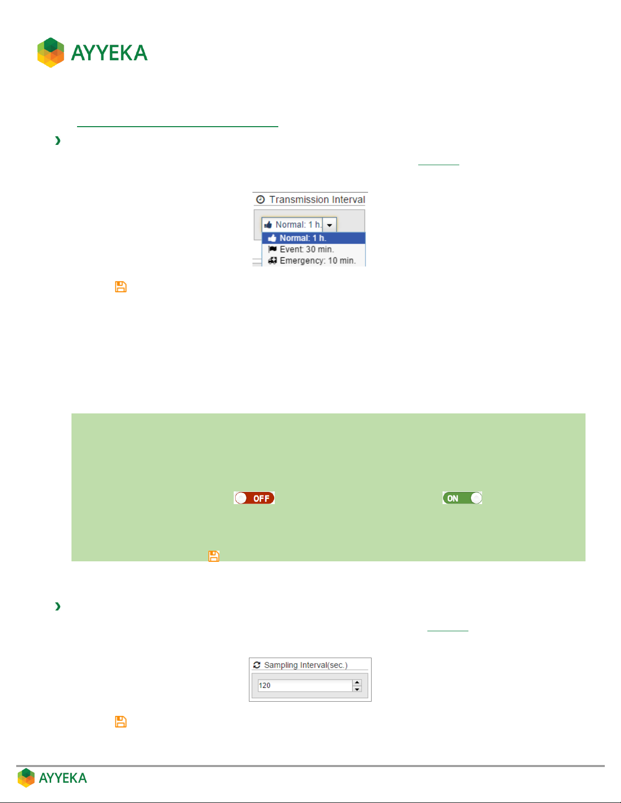
Note that you can set the Normal, Event and Emergency transmission intervals of a device. For instructions,
refer to Setting the Device Transmission Intervals.
To set the device transmission interval when samples are within a threshold range:
1. In the transmission Interval section of the threshold’s Actions view (Figure 56), select a transmission
interval from the drop-down list: Normal, Event or Emergency.
2. Click to save your settings.
Keep in mind that very short transmission intervals consume a large amount of power and network resources.
Note also that whenever a device is scheduled to transmit data, it transmits all the data it stored since its previous
transmission. Thus if you set the device to transmit at the Emergency rate for a certain threshold, then whenever
the threshold is reached and the device transmits at the Emergency rate, it will transmit data from all its data
streams, not only from the stream for which you defined the threshold.
Setting a Threshold’s Sampling Interval
In a nutshell:
1. Click Devices in the sidebar.
2. In the Sites Tree pane select the stream.
3. In the right pane select the Thresholds tab.
4. If the Thresholds slider is OFF , click it to switch Thresholds to ON .
5. In the threshold definition area, click Actions.
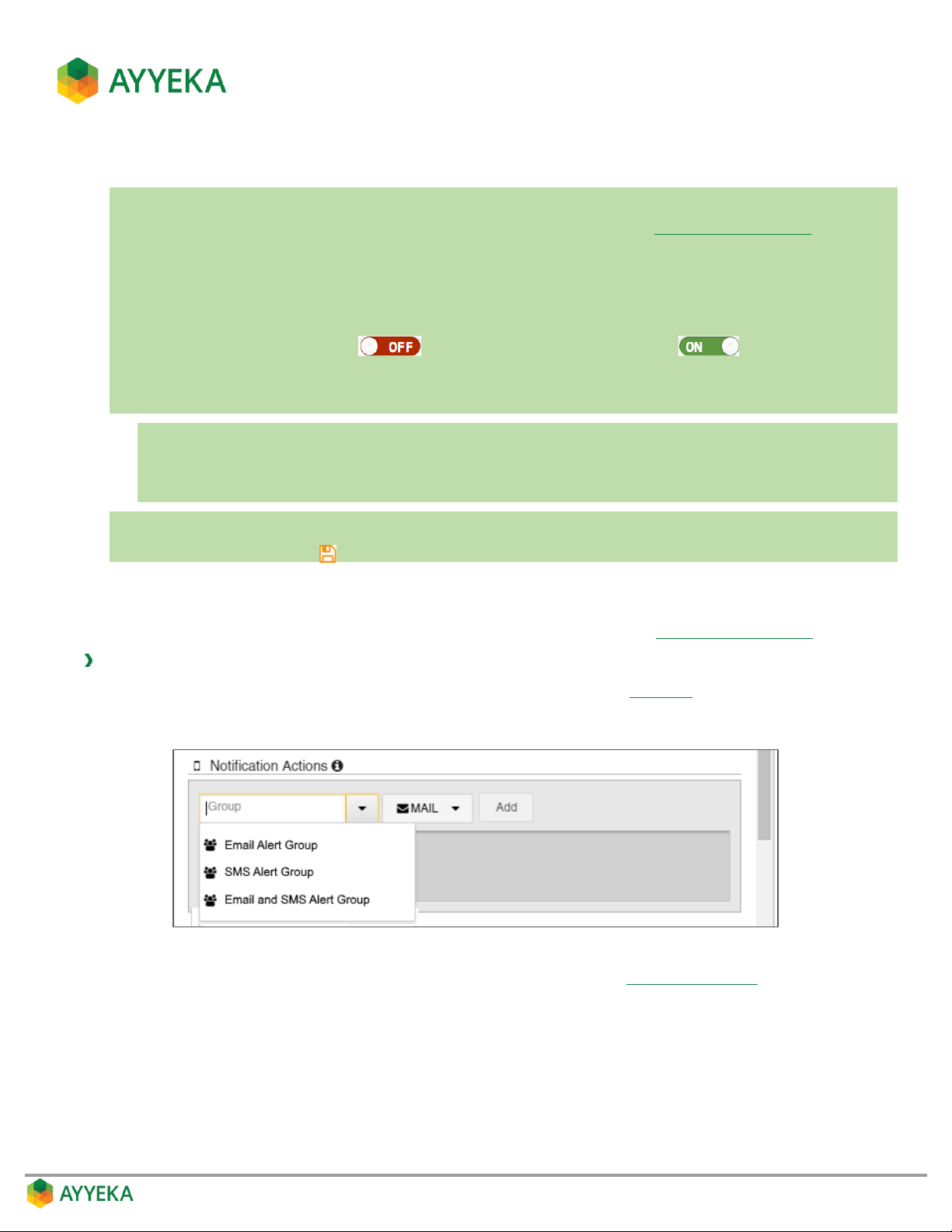
6. Under Sampling Interval, enter a value in seconds.
7. Save changes by clicking .
The sampling interval defines how often the device samples a data stream. You can specify the sampling interval
for the time periods when stream samples fall within a threshold range.
To define the stream sampling rate when samples are within a threshold range:
1. In the Sampling Interval (sec.) section of the threshold’s Actions view (Figure 56), select or enter a
sampling interval, in seconds.
2. Click to save your settings.
Page 72
Defining a Threshold’s Alert Recipients
In a nutshell:
To use this feature, you must first define Alert user groups, as described in Managing User Groups.
1. Click Devices in the sidebar.
2. In the Sites Tree pane select the stream.
3. In the right pane select the Thresholds tab.
4. If the Thresholds slider is OFF , click it to switch Thresholds to ON .
5. In the threshold definition area, click Actions.
6. Under Notification Actions:
a. Select a group.
b. Select whether to send an email and/or SMS.
c. Click Add.
7. Repeat the previous step for every additional group you want to add.
8. Save changes by clicking .
You can define which user groups will receive an alert whenever a stream sample crosses into a threshold range.
All members of the groups you specify will receive the alerts.
Note that to use this feature you need to first define user groups, as described in Managing User Groups.
To define which groups will receive alerts when samples enter a threshold range:
1. In the Notification Actions section of the threshold’s Actions view (Figure 56), perform the following:
a. Select a group in the drop-down list.
b. Select an alert medium – email and/or SMS. The message will be sent to the mobile phone number
or email address defined for each of the group’s users (refer to Inviting a New User).
Page 73
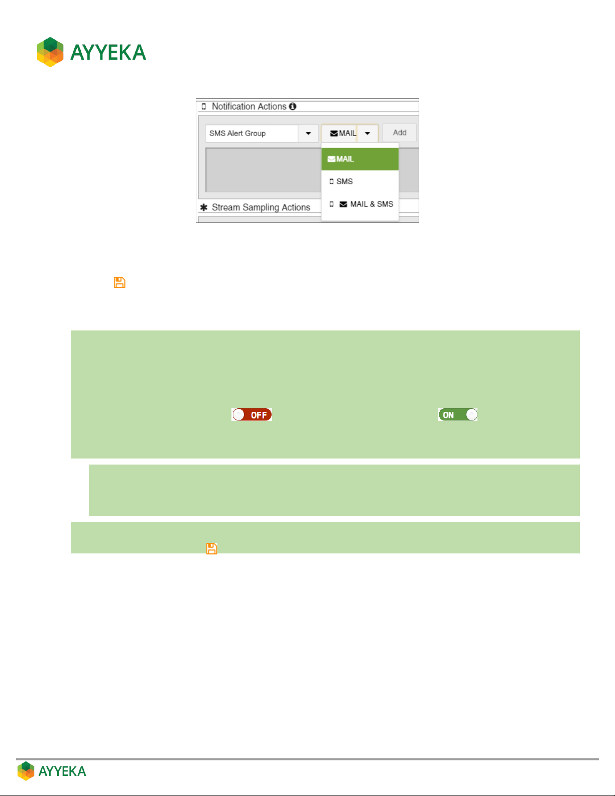
c. Click Add.
2. Repeat the previous step for every group to which you want to send a threshold alert.
3. Click to save your settings.
Setting Resultant Sampling Actions
In a nutshell:
1. Click Devices in the sidebar.
2. In the Sites Tree pane select the stream.
3. In the right pane select the Thresholds tab.
4. If the Thresholds slider is OFF , click it to switch Thresholds to ON .
5. In the threshold definition area, click Actions.
6. Under Stream Sampling Actions:
a. Select a data stream.
b. Select an action: Pause, Resume, Single or Pause Single.
c. Click Add.
7. Repeat the previous step for every additional action you want to add.
8. Save changes by clicking .
Page 74
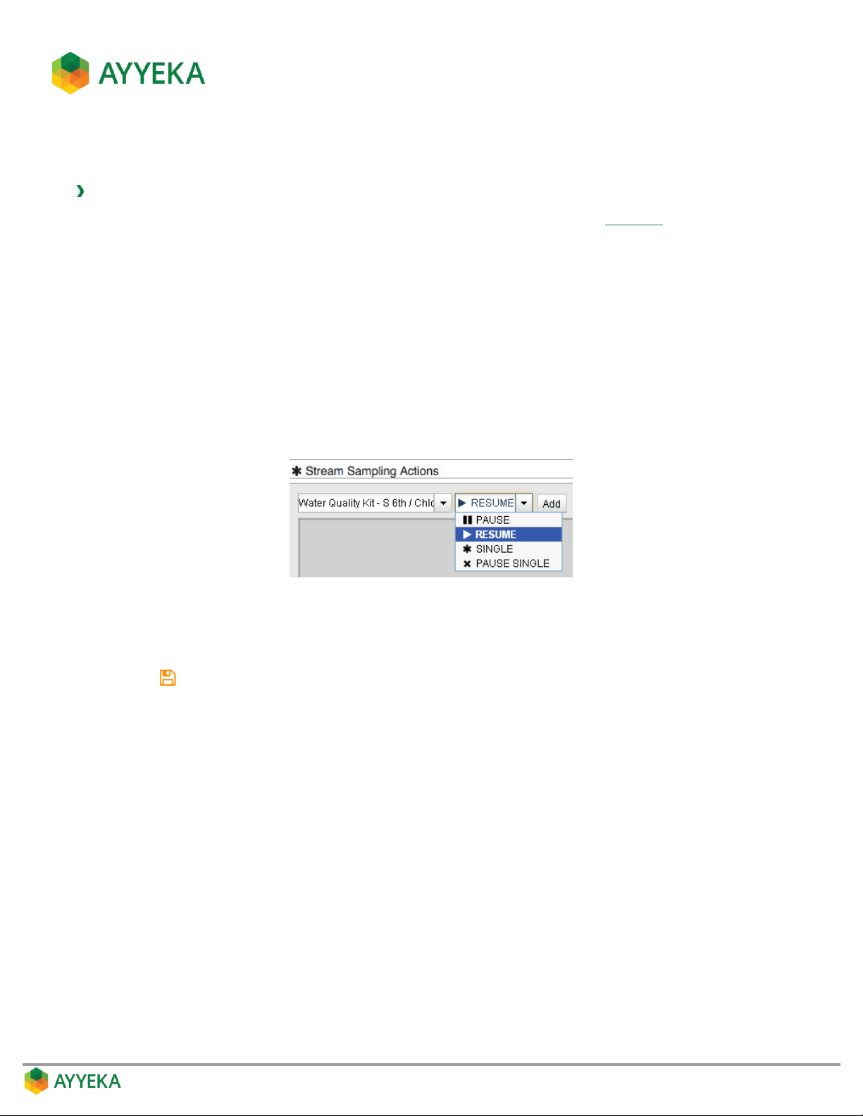
You can instruct a device to take a certain action for a specific data stream, whenever a stream sample crosses
into a threshold range.
To set stream sampling actions when samples enter a threshold range:
1. In the Stream Sampling Actions section of the threshold’s Actions view (Figure 56)), perform the
following:
a. Select a data stream in the drop-down list.
b. Select one of the following actions:
Pause – Instructs the device to pause sampling the selected data stream.
Resume – Instructs the device to resume sampling the selected data stream.
Single – Instructs the device to take a single sample of the selected data stream immediately
and then resume the regular sampling schedule for the selected data stream.
Pause Single – Instructs the device to immediately take one sample of the selected data stream,
and then pause sampling of this data stream.
c. Click Add.
2. Repeat the previous step for every data stream for which a certain sampling action should be taken
whenever data crosses into the threshold you are setting.
3. Click to save your settings.
Page 75
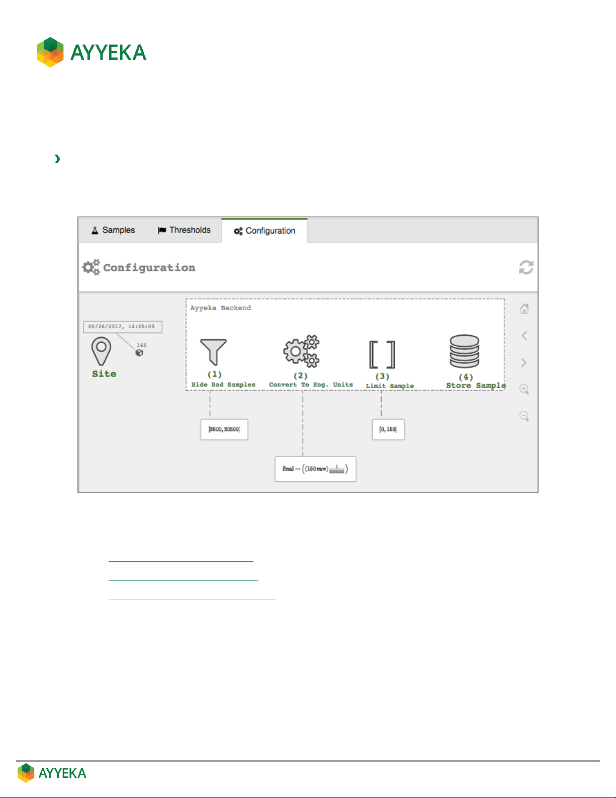
Viewing and Editing the Treatment of Raw Data
The Configuration tab of a data stream provides a visualization of the operations performed on the raw data
during the process of converting it to an engineering value.
To view or edit the treatment of raw data:
1. Click Devices in the sidebar, and click the stream name in the Sites Tree pane.
2. In the right pane, select the Configuration tab.
Figure 57: Selecting a stream’s Configuration tab
In the Configuration tab you can perform the following:
Hiding Bad Samples of Raw Data
Changing the Conversion Formula
Limiting Display of Engineering Values
Page 76
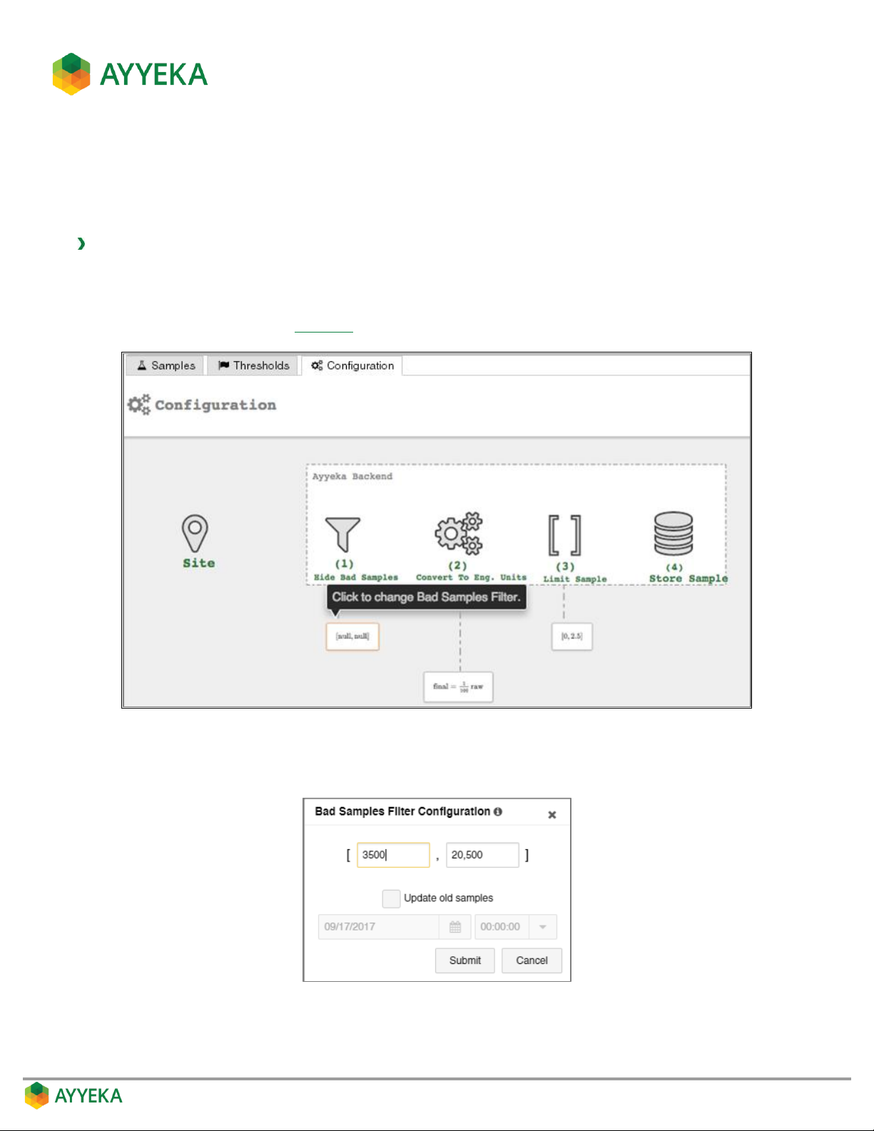
Hiding Bad Samples of Raw Data
You can set the minimum and maximum values for raw data. Raw data that is outside this range will be discarded.
This is useful in cases where you know that values outside this range are not real values, caused for example by
the sensor being disconnected from the Wavelet device.
To hide bad samples of raw data:
1. Click Devices in the sidebar, and click the stream name in the Sites Tree pane.
2. In the right pane, select the Configuration tab.
3. In the Configuration tab (Figure 57), click the frame under (1) Hide Bad Samples.
Figure 58: Selecting to change the Bad Samples filter
The Bad Samples Filter Configuration window appears.
Figure 59: Bad Samples Filter Configuration window
Page 77
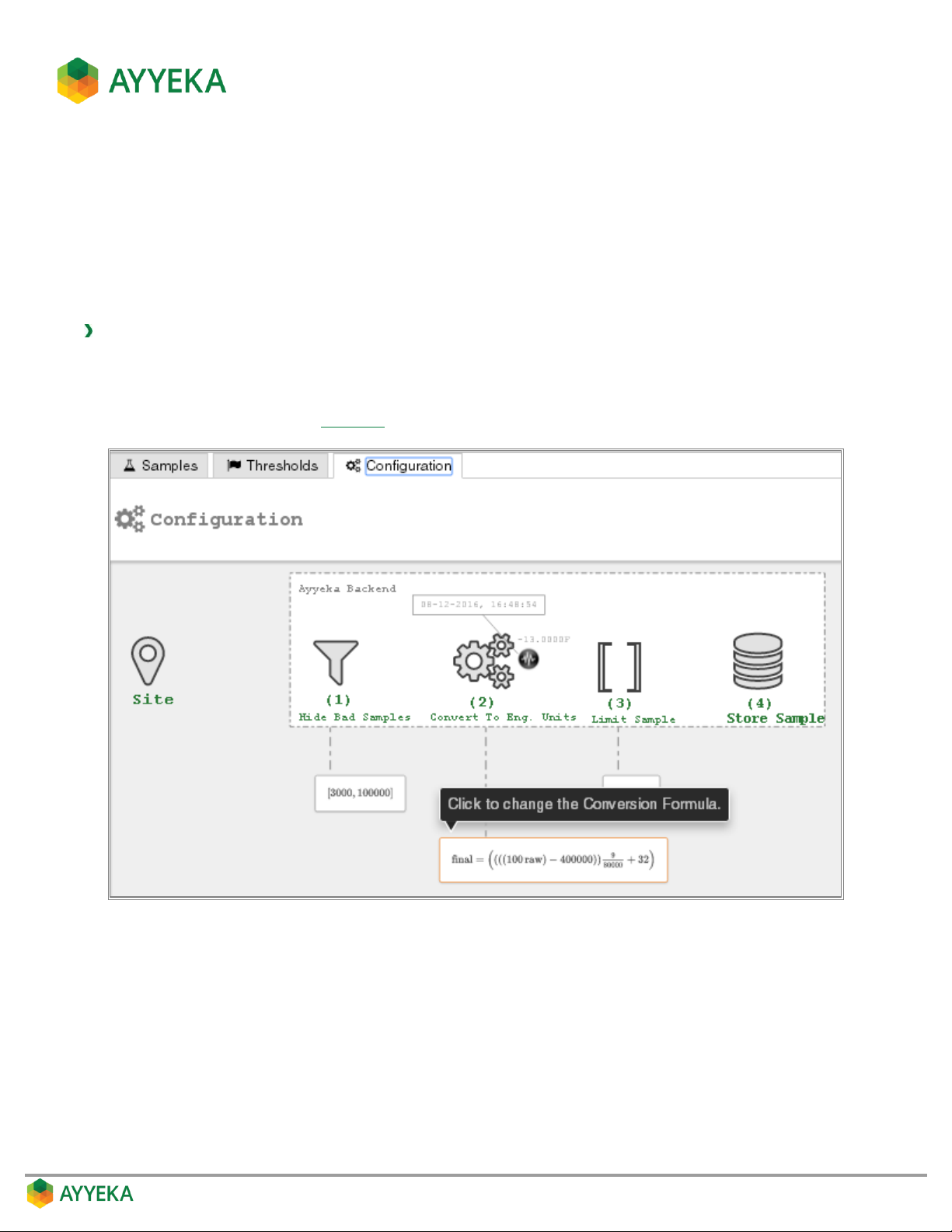
4. In the top two fields of the Bad Samples Filter Configuration window, set the minimum (left field) and
maximum (right field) values for raw data.
5. Click Update old samples to retroactively update old samples according to the new minimum and
maximum values. You can update samples up to two weeks back.
Changing the Conversion Formula
You can change the formula used to convert raw data into engineering units if the formula being used is linear.
To change the formula for converting raw data to engineering units:
1. Click Devices in the sidebar, and click the stream name in the Sites Tree pane.
2. In the right pane, select the Configuration tab.
3. In the Configuration tab (Figure 57), click the frame under (2) Convert To Eng. Units.
Figure 60: Selecting to change the conversion formula
Page 78
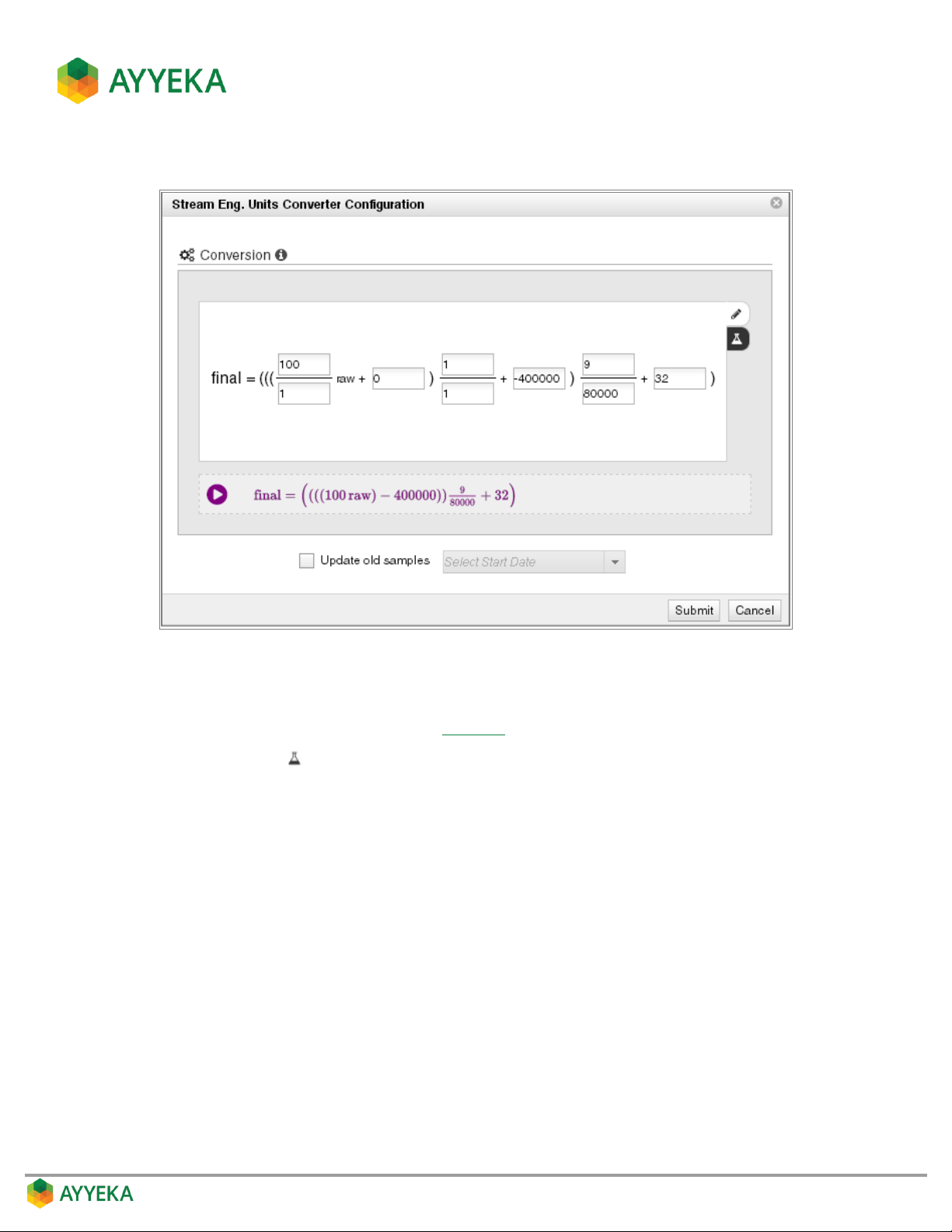
The Stream Eng. Units Converter Configuration window appears.
Figure 61: Raw Data Converter configuration – direct editing
4. Define the formula for converting raw data to engineering units in either of the following ways:
Edit the existing formula, as shown in Figure 61.
Click the beaker to define the formula by entering a pair of (Raw value, Final value) values. The
system will compute the actual formula.
Page 79
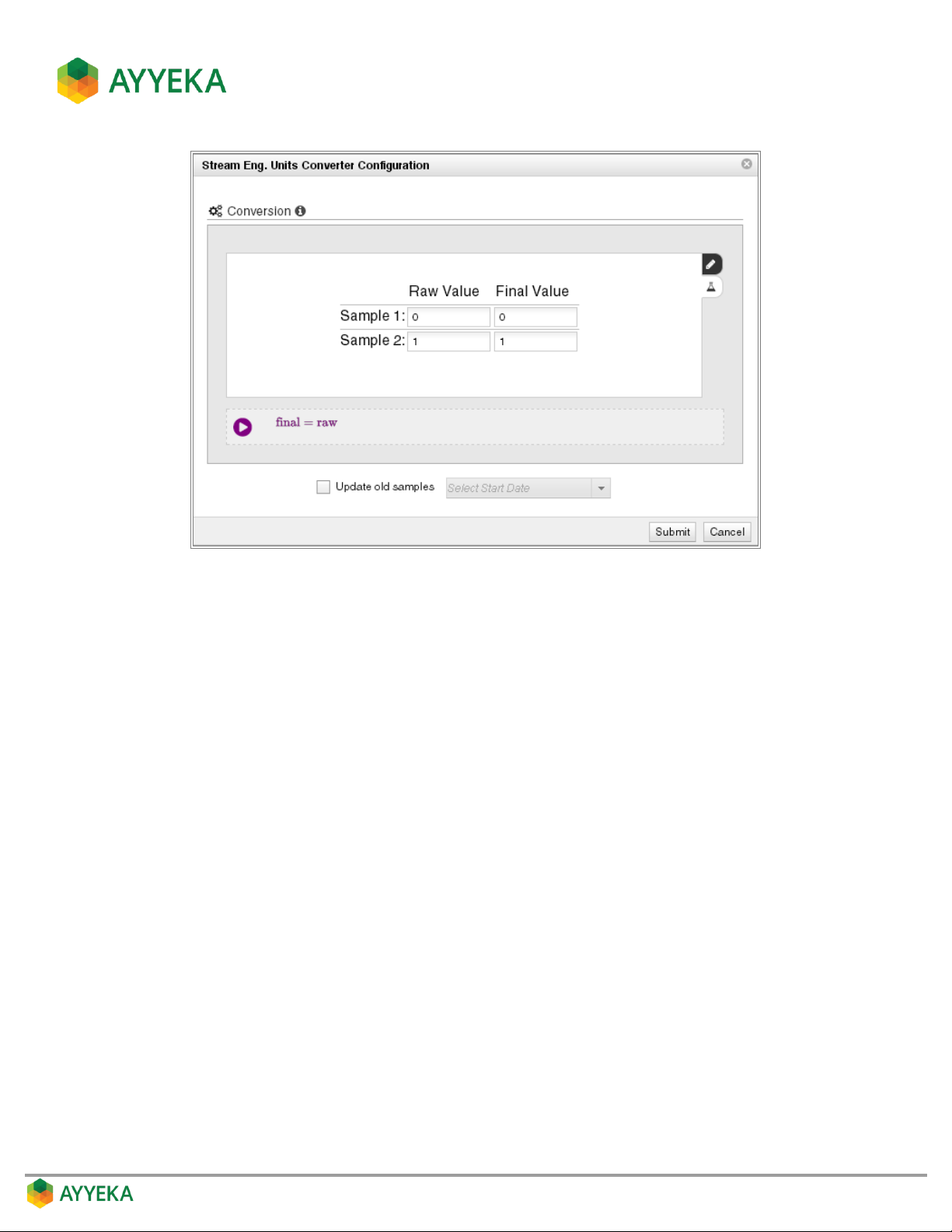
Figure 62: Raw Data Converter configuration – by extrapolation
5. Click Update old samples to retroactively update old samples according to the new conversion formula.
You can update samples up to two weeks back.
6. Click Submit.
Page 80
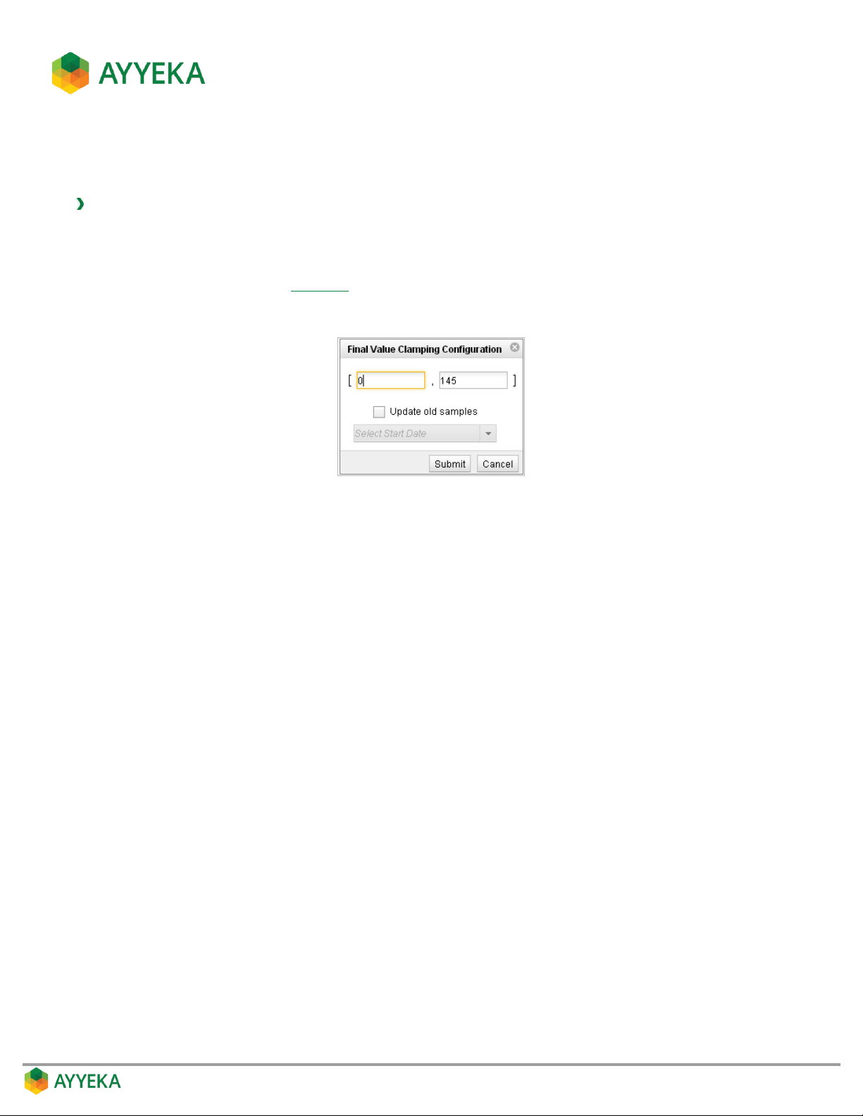
Limiting Display of Engineering Values
You can define how to round up and round down engineering values for display.
To limit the display of engineering values:
1. Click Devices in the sidebar, and click the stream name in the Sites Tree pane.
2. In the right pane, select the Configuration tab.
3. In the Configuration tab (Figure 57), click the frame under (3) Limit Sample.
The Final Value Clamping Configuration window appears.
Figure 63: Final Value Clamping Configuration window
4. Perform the following:
a. In the left field, enter a value for rounding up. For example, if you enter 0, all negative values will
display as 0.
b. In the right field, enter a value for rounding down. For example, if you enter 145, then all values
above 145 will display as 145.
5. Click Update old samples to retroactively update old samples according to the new clamping values.
You can update samples up to two weeks back.
6. Click Submit.
Page 81

Managing a Stream’s Sampling Interval
A stream’s sampling interval is the rate at which the Wavelet samples the relevant sensor for data. For example, a
sampling interval of 5 minutes means that the Wavelet samples the sensor every 5 minutes.
Ayyeka provides two default sampling interval values, called Sample Group 1 and Sample Group 2. Each stream, by
default, is a member either of Sample Group 1 or of Sample Group 2. In this way, each stream is given a sampling
interval value. The Sample Group 1 value and the Sample Group 2 value can be viewed and changed, as described
below. Ayyeka also provides a third option, which is to disassociate a stream from both sample groups, and assign
it a custom value instead.
Thus, a stream’s sampling interval can be set to any of the following:
The value of Sample Group 1. This value applies to all steams associated with Sample Group 1.
The value of Sample Group 2. This value applies to all steams associated with Sample Group 2.
A custom value, that applies to the specific stream only.
To find out a given stream’s sampling interval, refer to Discovering a Stream’s Sampling Interval Value.
To set a given stream’s sampling interval, you need to:
1. Find out whether the stream is associated with Sample Group 1 or Sample Group 2, or with neither of
them. Refer to Discovering a Stream’s Association with a Sample Group.
If the stream is associated with one of the groups – you can set the sampling interval of that group.
Note however that the value you set determines the sampling interval for all streams associated
with that group. Refer to Setting the Sampling Interval Value of a Sample Group.
If the stream is associated with neither of the groups – its sampling interval is a custom value. You
can change the stream’s custom sampling interval, and this will affect the specific stream only. Refer
to Setting a Stream’s Custom Sampling Interval Value.
2. In addition, you can change a stream’s association with the sample groups. That is, whatever its current
association, you can set a stream to be associated with Sample Group 1, or with Sample Group 2, or with
neither of them (and therefore its sampling interval is a custom value). Refer to Changing a Stream’s
Association with the Sample Groups.
Discovering a Stream’s Sampling Interval Value
To find out a stream’s sampling interval value:
1. Click Devices in the sidebar.
2. In the Sites Tree pane, click the device name.
3. In the right pane, click the Configuration tab.
The Stream Management table is displayed.
Page 82
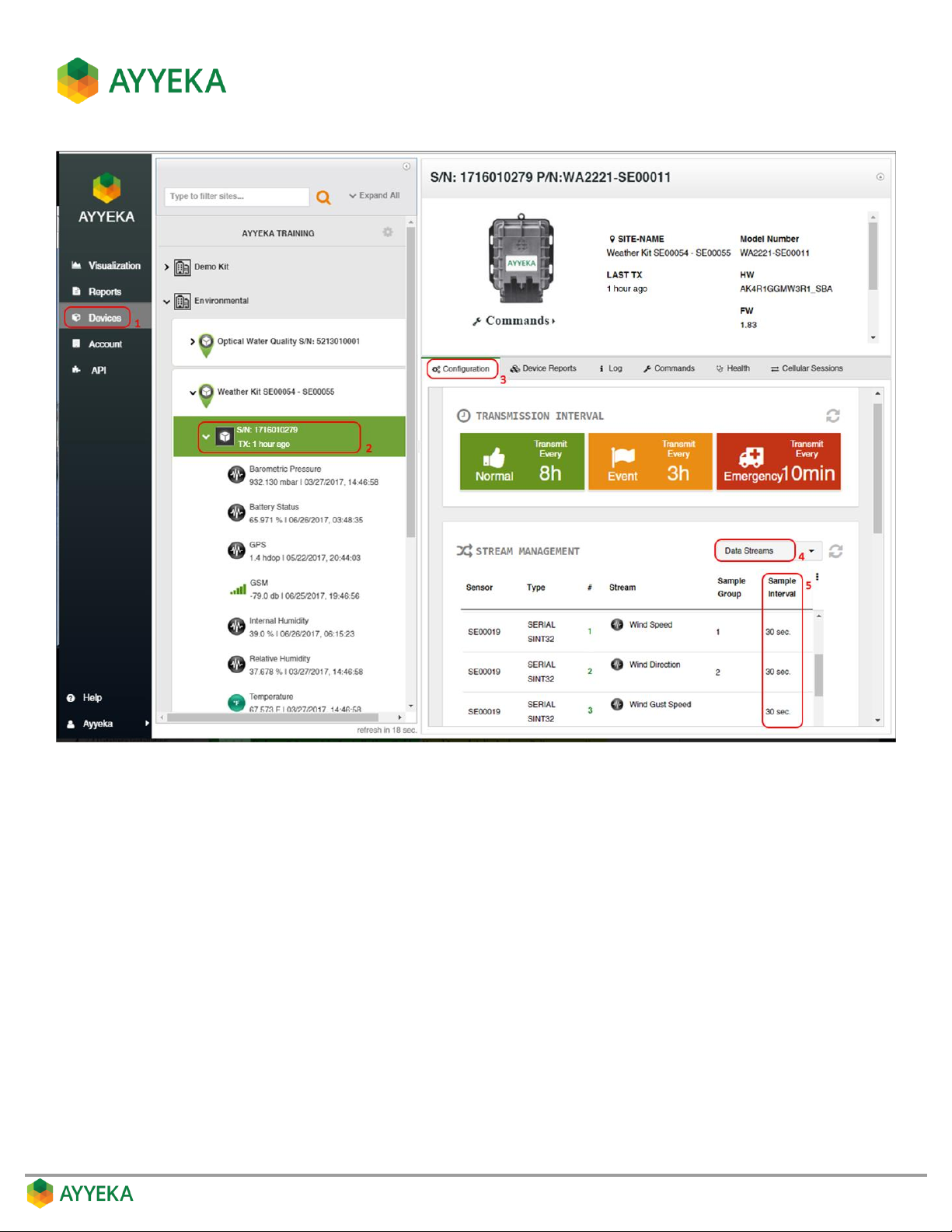
Figure 64: Viewing a stream’s sample interval
4. In the Stream Management table, make sure that Data Streams is selected in the top right drop-down
box.
5. In the Stream Management table, check the stream’s Sample Interval value, displayed in minutes. For
example, Figure 64 shows that the sampling interval of the Wind Speed stream is 30 seconds.
Page 83
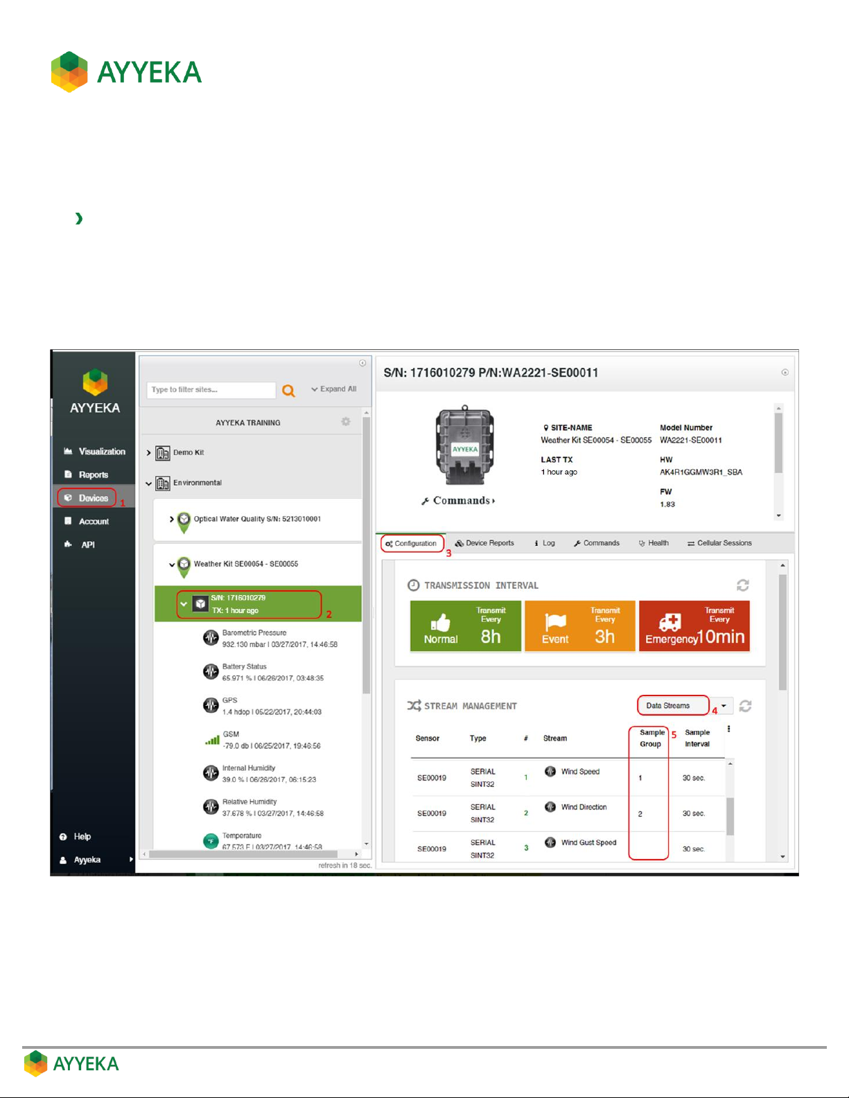
Discovering a Stream’s Association with a Sample Group
If you wish to change a stream’s sampling interval, you must first find out whether it is associated with Sample
Group 1 or Sample Group 2 group, or with neither of them.
To discover a stream’s association with a sample group:
1. Click Devices in the sidebar.
2. In the Sites Tree pane, click the device name.
3. In the right pane, click the Configuration tab.
The Stream Management table is displayed.
Figure 65: Viewing a stream’s Sample Interval Group
4. In the Stream Management table, make sure that Data Streams is selected in the top right drop-down
box.
5. In the Stream Management table, the stream’s Sample Group value indicates the following:
1 – The stream is associated with Sample Group 1.
Page 84
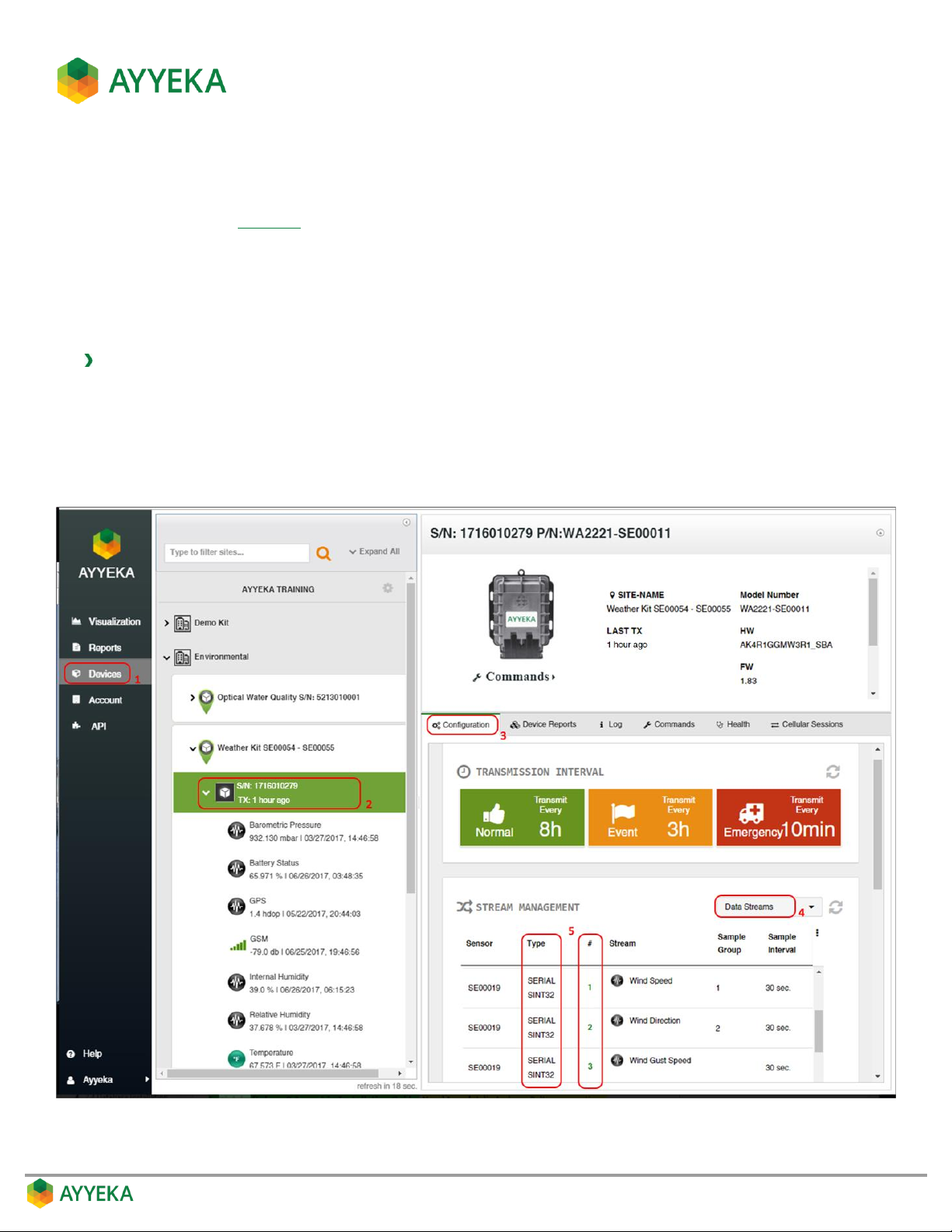
2 – The stream is associated with Sample Group 2.
Empty cell – The stream is configured to accept a custom sampling interval value.
For example, Figure 65 shows that the Wind Speed stream is associated with Sample Group 1, the Wind
Direction stream is associated with Sample Group 2, while the Wind Gust Speed stream is configured
to accept a custom sampling interval value.
Changing a Stream’s Association with the Sample Groups
You can change any specific stream’s association with a sample group.
To change a stream’s association with the sample groups:
1. Click Devices in the sidebar.
2. In the Sites Tree pane, click the device name.
3. In the right pane, click the Configuration tab.
The Stream Management table is displayed.
Figure 66: Viewing a stream’s Type and Number
Page 85
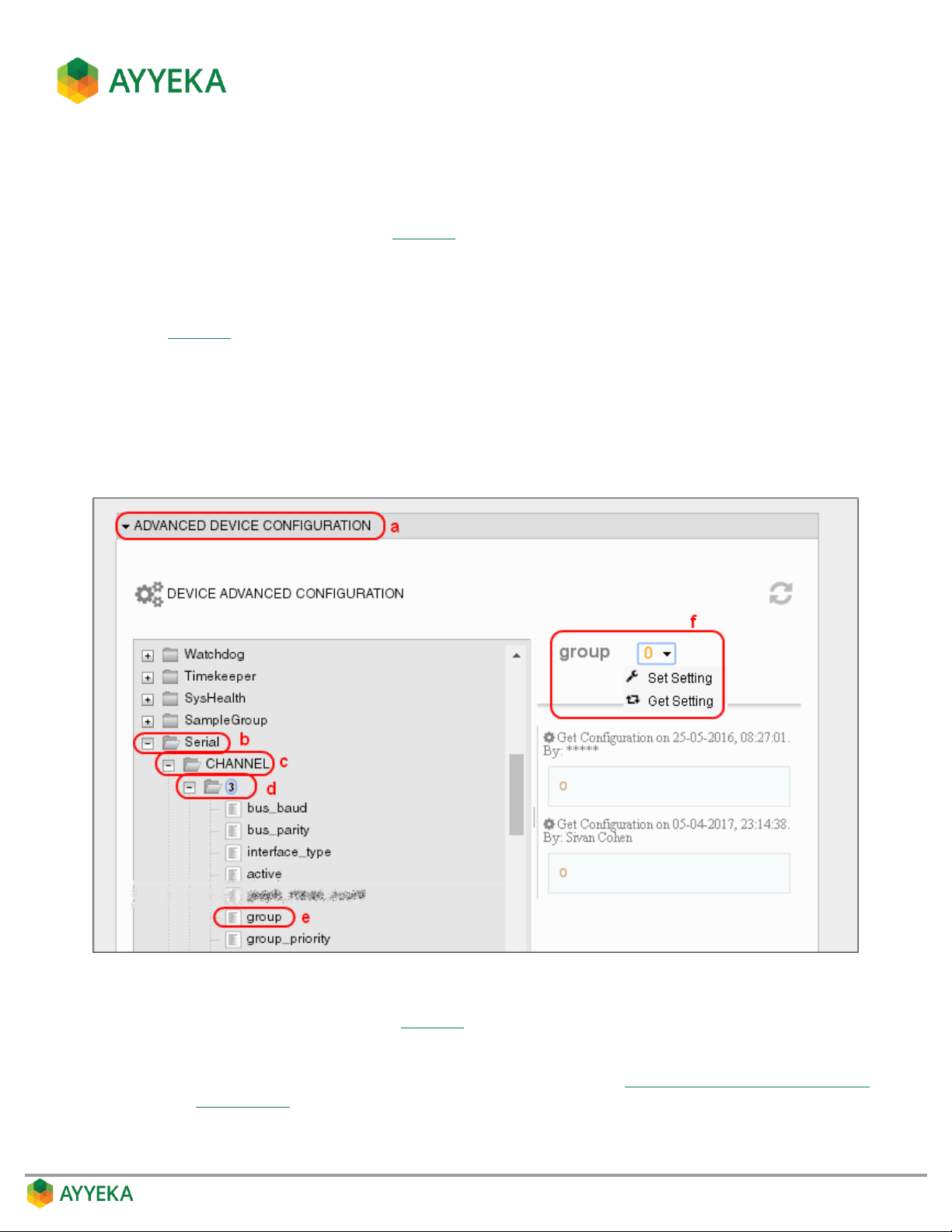
4. In the Stream Management table, make sure that Data Streams is selected in the top right drop-down
box.
5. Locate the stream in the Stream Management table, and note its Type (stream type) and # (stream
number). In the example shown in Figure 66, the Wind Gust Speed stream’s Type=Serial, and
Number=3.
6. Perform the following:
a. Scroll to below the Stream Management table, and click Advanced Device Configuration (Step a in
Figure 67).
b. In the configuration tree, expand the node whose name is the stream’s type. In our example, this is
the Serial node.
c. Expand the CHANNEL node.
d. Expand the node whose name is the stream’s number. In our example, this is the 3 node.
e. Select the group node
Figure 67: Determining the sample group
f. Set the value of group (step f in Figure 67) as follows:
Group=0: This stream is not associated with any Sample Group.
Its value is custom set, and can be changed as described in Setting a Stream’s Custom Sampling
Interval Value.
Page 86
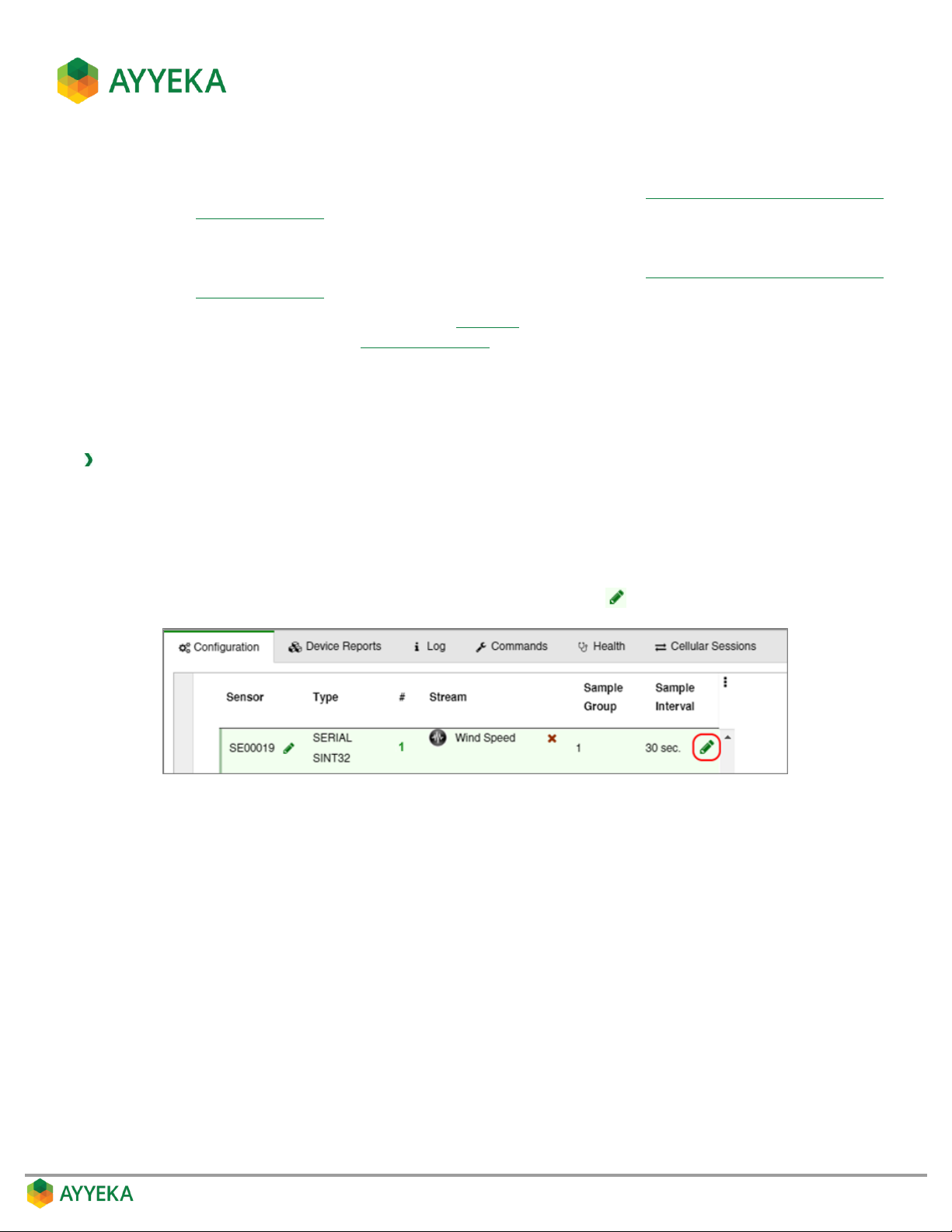
Group=1: This stream is associated with Sample Group 1.
You can set the sampling interval of the group as described in Setting the Sampling Interval Value
of a Sample Group.
Group=2: This stream is associated with Sample Group 2.
You can set the sampling interval of the group as described in Setting the Sampling Interval Value
of a Sample Group.
7. If you changed the value of group (step f in Figure 67), you must reboot the device in order for the
change to take effect. Refer to Rebooting a Device.
Setting the Sampling Interval Value of a Sample Group
You can set the sampling interval of Sample Group 1 or Sample Group 2. Note that the value you set determines
the sampling interval for all streams associated with that group.
To set the sampling interval of a sample group:
1. Click Devices in the sidebar.
2. In the Sites Tree pane, click the relevant device.
3. In the right pane, click the Configuration tab.
4. In the Stream Management table, hover over the line displaying the number of the sample group
whose sampling interval you wish to modify. A green pencil icon appears at the right end of the line.
Figure 68: Option for modifying the Sampling Interval
Page 87
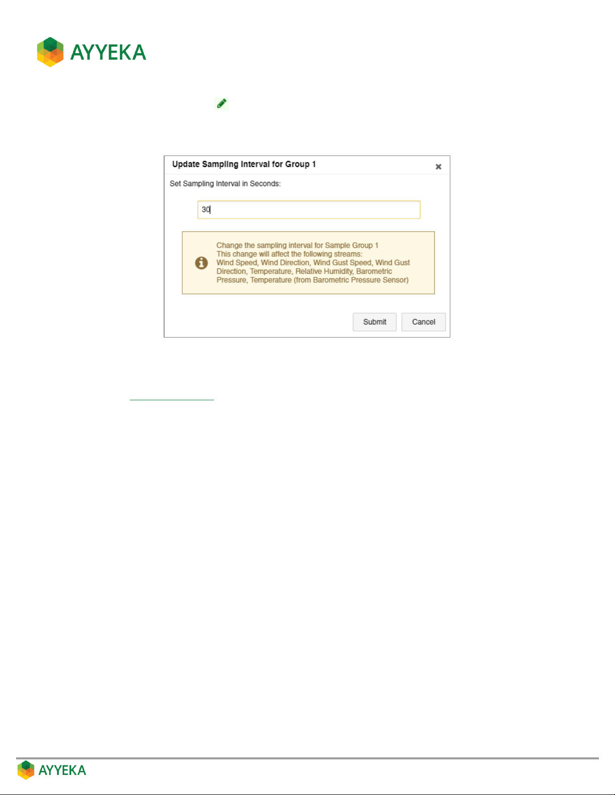
5. Click the green pencil icon :
6. In the Update Sampling Interval for Group window that appears, modify the value of the sampling
interval in seconds.
Figure 69: Setting the sampling interval for a Sample Group
7. If you changed the sampling interval, you must reboot the device in order for the change to take effect.
Refer to Rebooting a Device.
Page 88
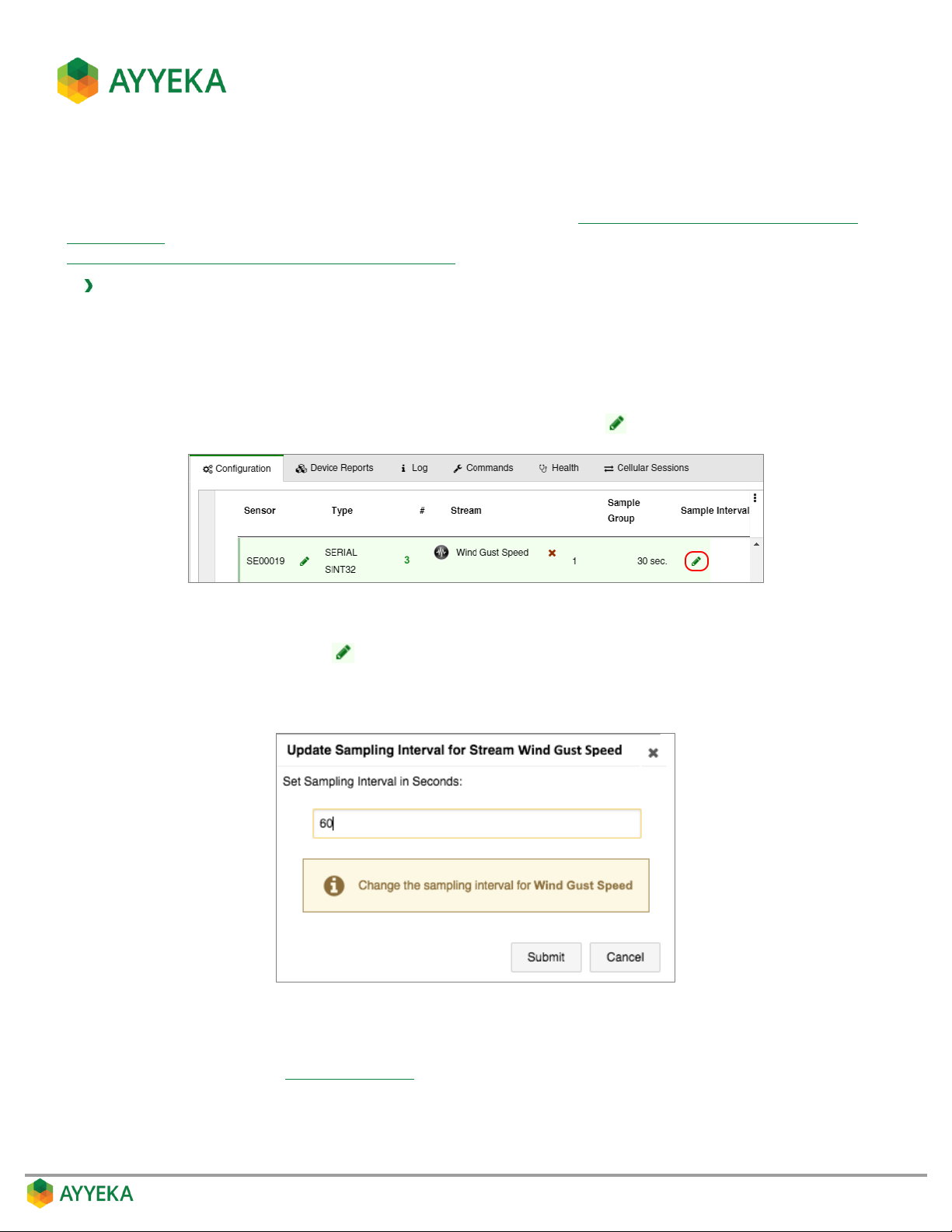
Setting a Stream’s Custom Sampling Interval Value
You can change a specific stream’s custom sampling interval value. However, first check whether the stream is
configured to accept a custom sampling interval value, as described in Discovering a Stream’s Association with a
Sample Group. If it is not, configure the stream to accept a custom sampling interval value, as described in
Changing a Stream’s Association with the Sample Groups.
To set a stream’s custom sampling interval:
1. Click Devices in the sidebar.
2. In the Sites Tree pane, click the device name.
3. In the right pane, click the Configuration tab.
4. In the Stream Management table, hover over the line displaying the number of the sample group
whose sampling interval you wish to modify. A green pencil icon appears at the right end of the line.
Figure 70: Option for modifying the Sampling Interval
5. Click the green pencil icon :
6. In the Update Sampling Interval window that appears, modify the value of the sampling interval in
seconds.
Figure 71: Setting a custom sampling interval
7. If you changed a stream’s sampling interval value, you must reboot the device in order for the change to
take effect. Refer to Rebooting a Device.
Page 89
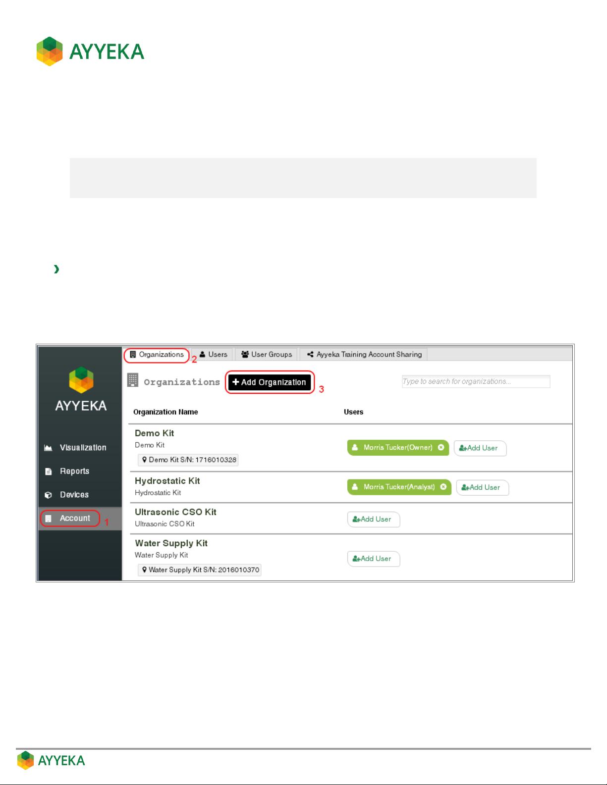
MANAGING ORGANIZATIONS
An account owner can add or edit organizations.
Note: If you are setting up your account and intend to add organizations, it is recommended to
do so before creating users. This will enable you to create users in their appropriate
organizations.
Adding an Organization
An account owner can create organizations and assign to them sites.
To add an organization
1. Click Account in the sidebar.
2. In the right pane, select the Organizations tab.
3. Click + Add Organization.
Figure 72: Selecting to add an organization
Page 90
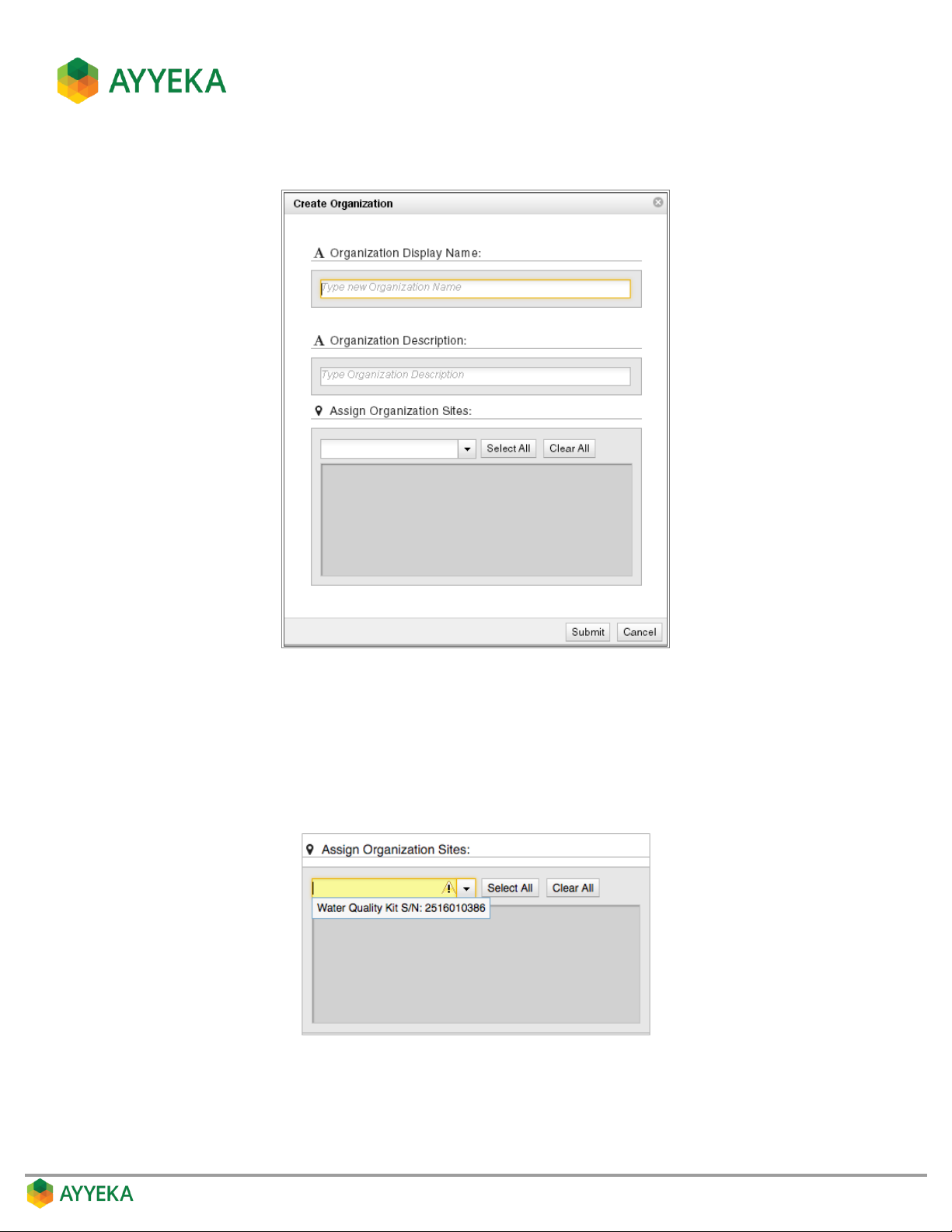
The Create Organization window appears.
Figure 73: Create Organization window
4. In the Create Organization window:
a. Enter a name for the organization.
b. Optionally enter a description.
c. Specify which sites you are assigning to the organization.
Figure 74: Assigning sites to an organization
Page 91
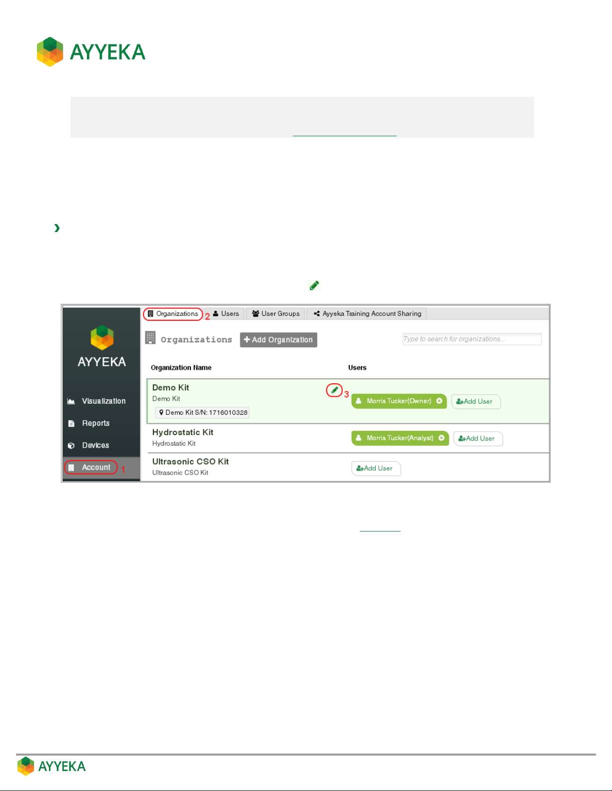
Note: A site can belong to only one organization.
If you wish to assign to Org1 a site that is currently assigned to Org 2, you must first
remove the site from Org2 (refer to Editing an Organization), and then assign it to Org1.
5. Click Submit.
Editing an Organization
An account owner can edit the name, description, and assigned sites of an existing organization.
To edit an organization:
1. Click Account in the sidebar.
2. In the right pane, select the Organizations tab.
3. In the list of organizations, click the pencil icon adjacent to the organization you wish to edit.
Figure 75: Selecting to edit an organization
The Update Organization window appears (very similar to Figure 73).
4. In the Update Organization window, change the organization’s name, description, or assigned sites.
5. Click Submit.
Page 92
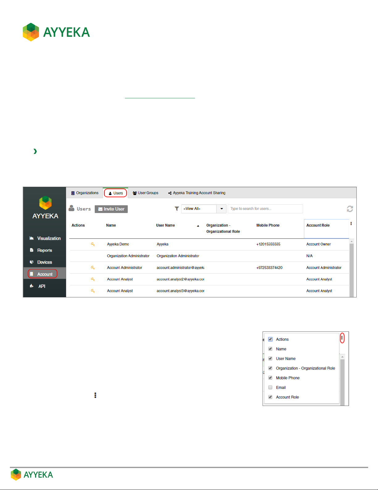
MANAGING USERS
Users are managed by assigning them to an organization or account, and assigning them roles. A user’s role
defines his permitted actions (see Understanding User Roles).
Viewing the List of Users
You can view all the users in your organization (if you are an Organization owner), or in your account (if you are an
account owner).
To view all users:
1. Click Account in the sidebar.
2. In the right pane, select the Users tab.
Figure 76: Users window
The Users table shows, for each user in your organization (or account):
The user’s name
The user’s login name
The user’s organization, and his Organizational Role
The user’s mobile phone number
The user’s Account Role (if any)
You can click in the top right to select to display also the user’s
Email address.
Page 93
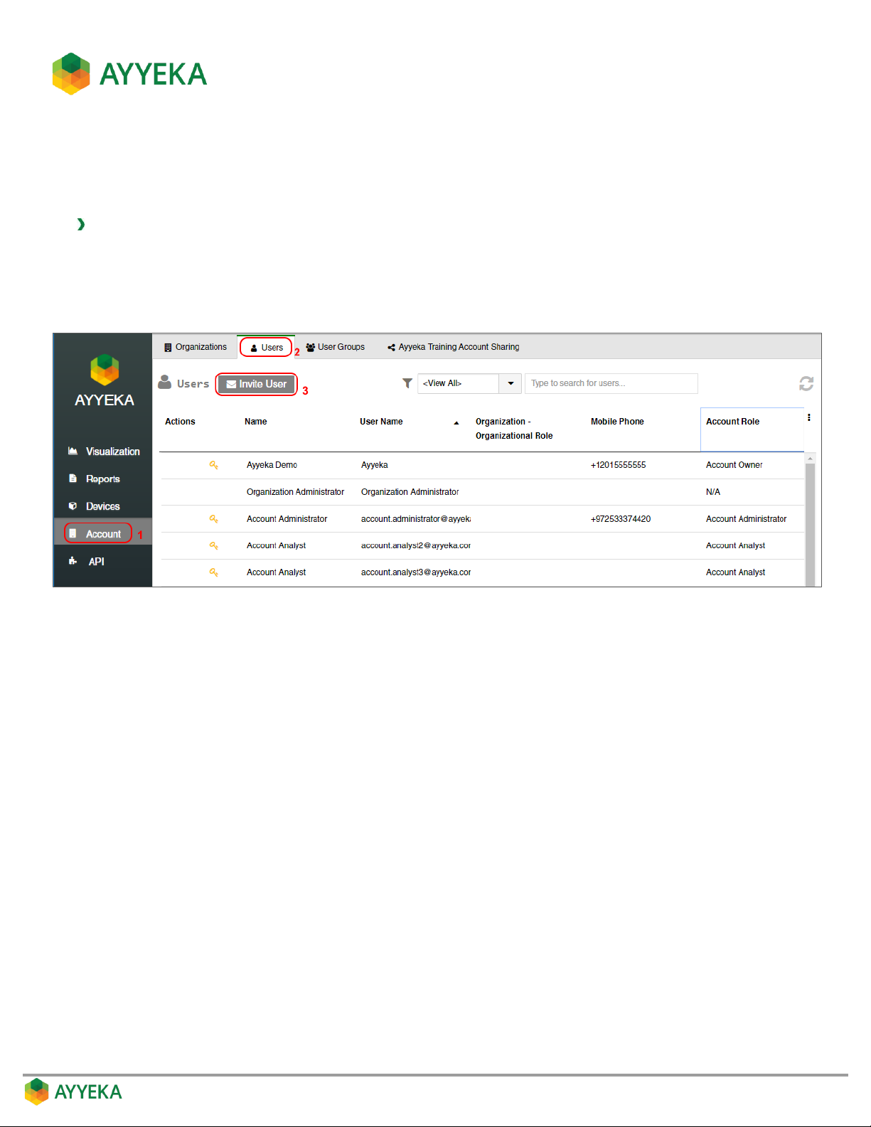
Inviting a New User
A user with an Account Owner role can add new users at either the account or organization level, while a user with
an Organization Owner role can add new users to his organization only.
To add a new user at the account or organization level:
1. Click Account in the sidebar.
2. In the right pane, select the Users tab.
3. Click Invite User.
Figure 77: Selecting to Invite User – at the Account level
The Invite User window appears.
Page 94
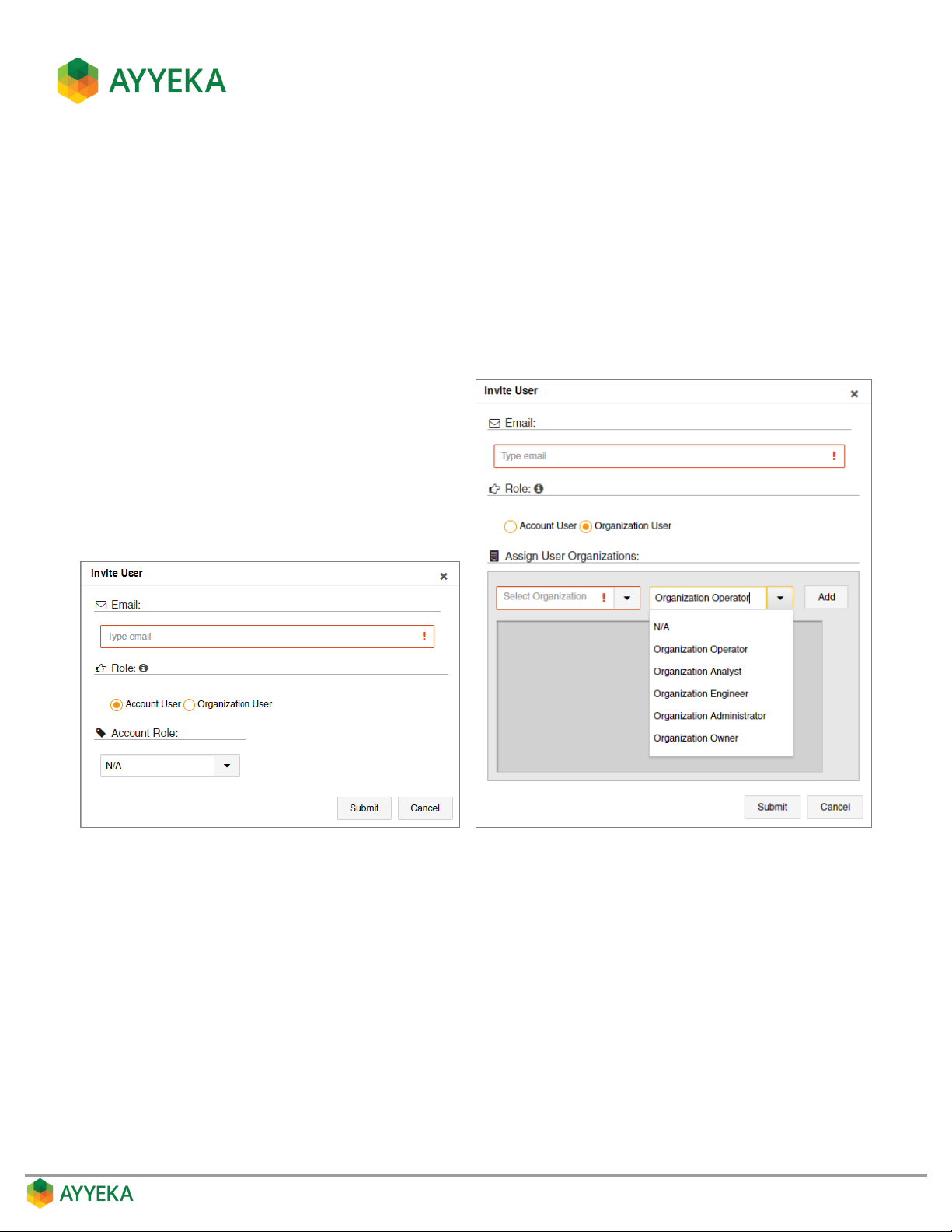
4. In the Invite User window:
a. Enter the user’s email address. This is the address to which the invitation will be sent.
b. In the Role section, specify whether the user will be an Organization User or Account User:
If you are creating an Account User, select a role for the user.
If you are creating an Organization User, you can give the user roles in multiple organizations. To
do so, select an organization and a role, and click Add. Repeat these actions for every
organization in which you wish to assign the user a role.
c. Click Submit.
Figure 78: Invite User window – Account User (Left) or Organization User (Right)
Page 95

5. An invitation to access the Ayyeka Management Console is sent by email to the newly invited user.
To accept, the new user clicks Accept Invitation in the email message
Figure 79: Ayyeka Invitation email message
Page 96
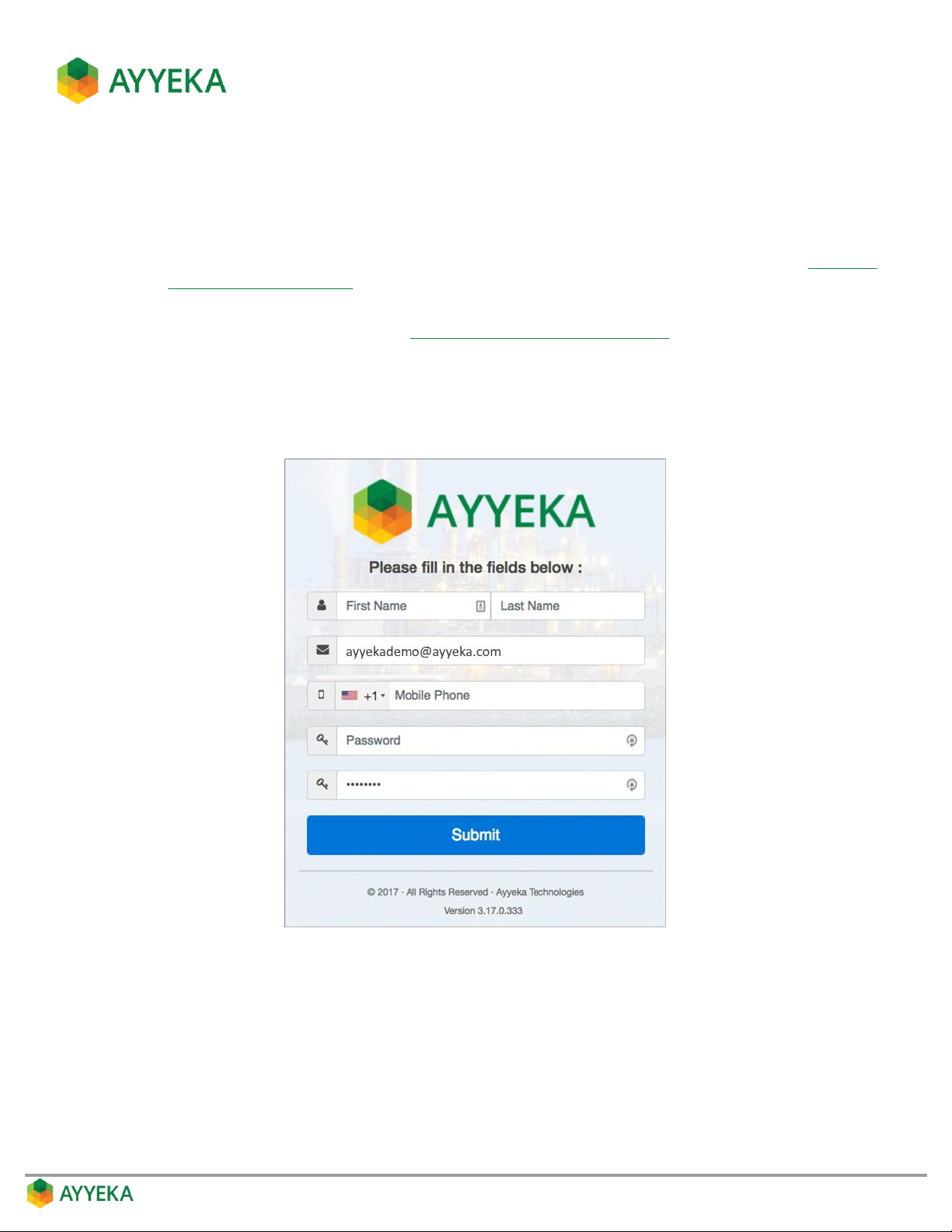
6. An Ayyeka Management Console page opens in the new user’s browser, displaying an Invited User
Details window. The new user should:
a. Enter the user’s actual First Name and Last Name.
b. Optionally change the email address, which currently lists the email address to which the invitation
was sent. Note that threshold alerts will be sent to this address/mobile number (refer to Defining a
Threshold’s Alert Recipients).
c. Optionally enter a mobile phone number. Note that threshold alerts will be sent to this
address/mobile number (refer to Defining a Threshold’s Alert Recipients).
d. Enter a password, and confirm the password. Note that a green line appearing under the password
box indicates a strong password; an orange line indicates a medium-strength password; and a red
line indicates an insufficiently-strong password.
e. Click Submit.
Figure 80: Invited User Details window
Page 97
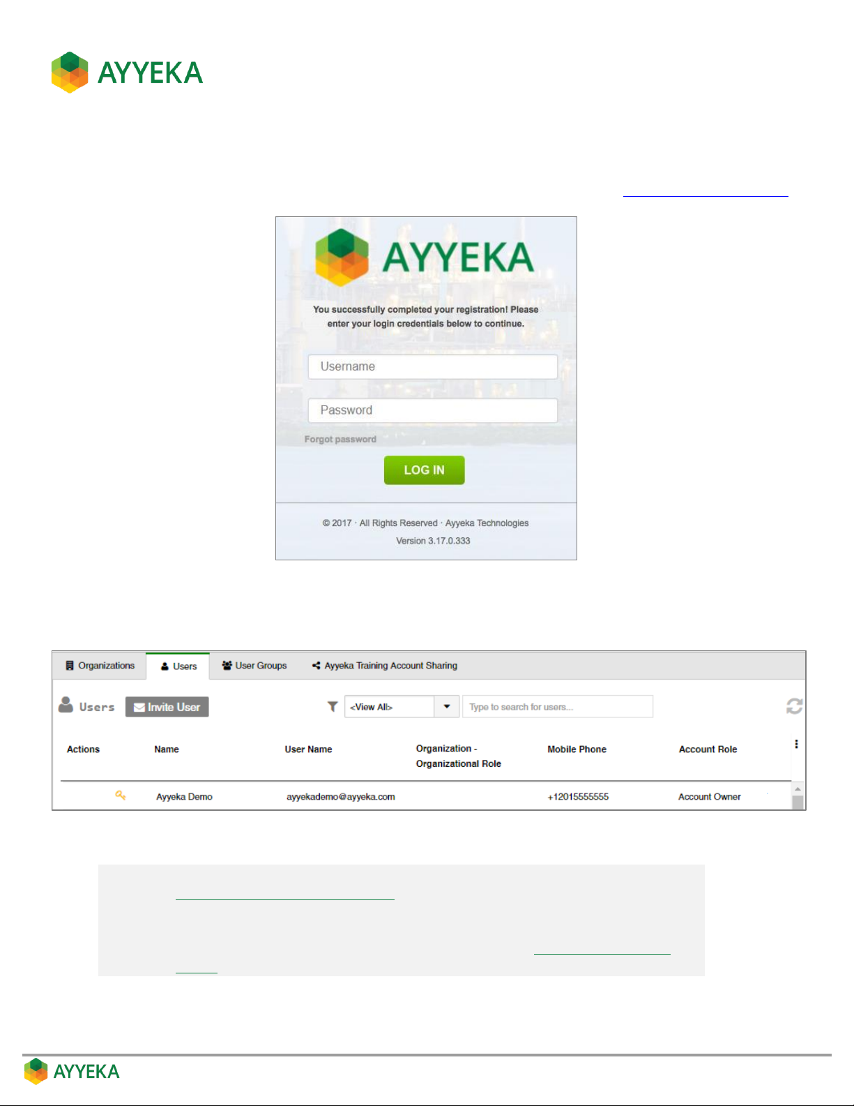
7. Upon a successful submission, a login window with a successful registration message appears. The new
user can enter his username and password to log into the Ayyeka Management Console.
To access the Ayyeka Management Console anytime, the user can browse to https://home.ayyeka.com.
Figure 81: Login window following successful new user registration
The new user is added to the users table, as shown below.
Figure 82: User successfully added to account
Note: The user details can be changed and managed by an owner, as described in
Editing, Disabling or Deleting a User.
Note also that any logged-in user can change most of his own user details, such
as email, mobile phone, and password, as described in Setting Your Own User
Details.
Page 98
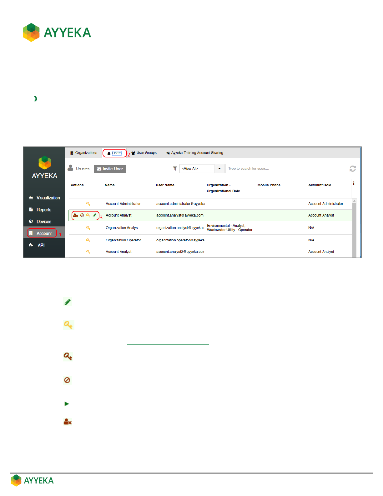
Editing, Disabling or Deleting a User
An account owner can edit/disable/delete users at either the account or organization level, while an organization
owner can edit/disable/delete users of his organization only.
To edit, disable or delete a user:
1. Click Account in the sidebar.
2. In the right pane, select the Users tab.
3. Hover over the line of the user you wish to modify. Several icons appear to the left of the user’s Name.
Figure 83: Options for modifying a user
4. Select the icon corresponding to the action you wish to take:
Edit user settings. Click this icon and edit the settings in the Edit User Properties
window that appears.
Indicates the user has a valid password. Click this icon to change the existing
password. Note that the logged-in user can change his own password, as
described in Changing your own password.
Indicates the user password has expired. Click this icon to define a new
password.
Deactivate the user. A deactivated user does not receive threshold alerts and
cannot access the UI, but is not deleted from the database.
Activate a deactivated user.
Delete the user from the database.
Page 99
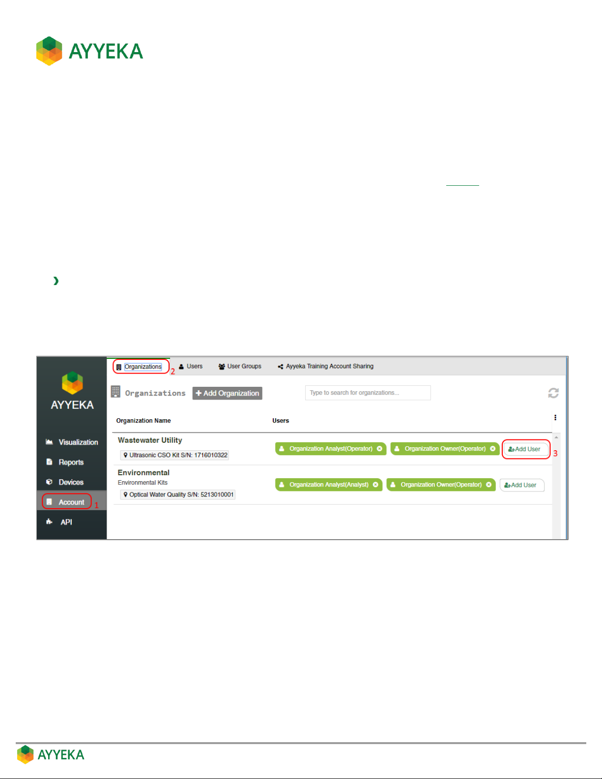
Adding Existing Users to Organization(s)
An account owner can give an organization user, permissions in more than one organization. For example, you
may wish to grant the Organization Owner of Org1 permission to view the sites and streams (=Operator
permissions) in Org2 and Org3. In this case you would give this user an Organization Owner role in Org1, an
Organization Operator role in Org2, and an Organization Operator role in Org3.
Note that a similar mechanism exists for giving users certain permissions to sites, called Sharing. The differences
between Sharing sites and adding users to an organization, are:
Sharing gives permissions to specific sites, not to all an organization’s sites.
Sharing bestows Analyst (viewing and reporting) permissions only, while a user who is added to an
organization can be given any role.
To add an existing user to an organization:
1. Click Account in the sidebar.
2. In the right pane, select the Organizations tab.
3. Click + Add User in the Users column of the organization to which you want to add a user.
Figure 84: Selecting to add a user to an organization
The Add User to Organization window appears.
Page 100
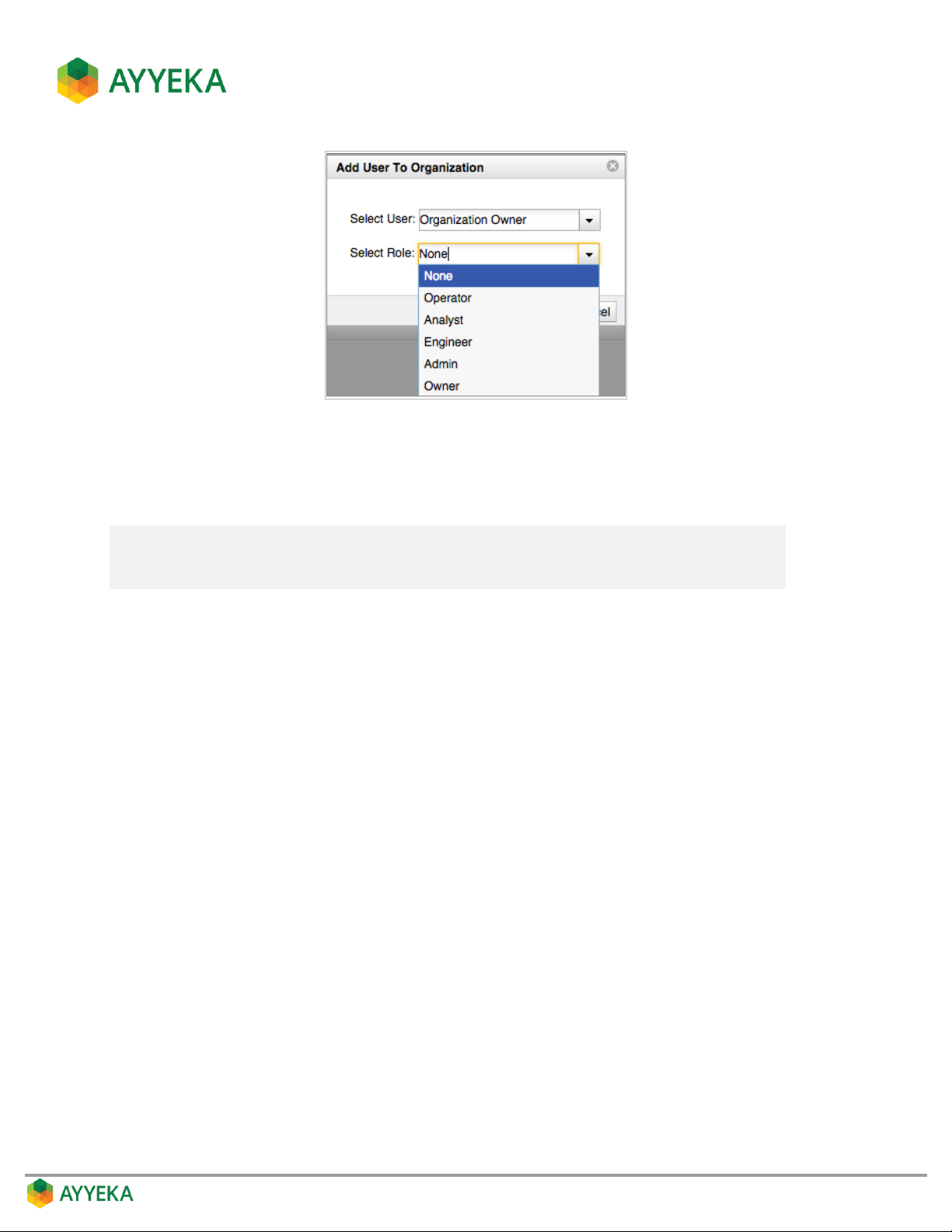
Figure 85: Assigning a role to a user
4. In the Select User drop-down list, specify which user to add to the organization.
5. In the Select Role drop-down list, specify the user’s role in this organization.
Note: If the role assigned here is not identical to the role assigned to the user upon
user creation, the system grants him permissions to the organization’s assets
that correspond to the higher of the two roles.
 Loading...