

AXTON A480DSP Installation & Operation Manual
A480DSP
4-CHANNEL SMART DIGITAL AMPLIFIER
INSTALLATION & OPERATION MANUAL
EINBAU & BEDIENUNGSANLEITUNG

Thank you for purchasing this innovative AXTON amplier!
To maximize the performance of this amplier and your complete car audio system
install, we recommend that you acquaint yourself thoroughly with all technical features
and controlling options of this AXTON amplier. Please read this manual carefully, before
attempting the installation. If, after reading this manual, you still have questions regarding
functions or the installation of the amplier, we recommend that you consult your dealer.
– 2 –

SAFETY INSTRUCTIONS
n Do not turn on any function which may distract you while driving the vehicle.
Functions requiring sustained attention must only be used when the vehicle is at a
complete standstill. Make sure to always stop your vehicle in a safe place before
operating these functions. There is a risk of causing an accident.
n Keep the volume at a low level to be able to hear exterior noises while driving
the vehicle. There is a risk of causing an accident.
n Do not open the amplier or undertake any modication of the product. There
is a risk of accident, re or electric shock.
n Only use this amplier with 12V mobile applications. Any other use other than
the use for which this product has been designed may lead to re, electric shock or
injury.
n Use fuses of the correct amperage. There is a risk of re or electrocution.
n Do not obstruct radiators and/or vents. Internal overheating may occur and cause
a re.
n Ensure all connections are properly made. Check the section of cable and the
type of cable if it does not correspond with the use. There is a risk of re, injury and/
or damage to the product.
n Do not use nuts or fasteners part of the steering or braking systems for ground
connection. The fasteners and nuts used for the brake and steering systems (or any
other security system) as well as various tanks must never be used for grounding.
Use of these parts as ground may deactivate the vehicle’s control system and cause
a re or other technical problem.
n Keep all small objects which could be swallowed, such as the fasteners and
screws, out of the reach of children. Swallowing such objects may cause serious
injuries. In the event of swallowing any of these objects, immediately seek medical
advice.
n Before starting the installation, disconnect the negative terminal of the battery
to avoid any risk of injury, re or damage to the equipment.
– 3 –

TECHNICAL SPECIFICATIONS
Music Power Output:
RMS Power Output:
Frequency response:
Audio sampling frequency:
Distortion:
Supply voltage range:
150 W x 4 (110 W x 4*)
76 W x 4 (56 W x 4*)
20 Hz ~ 20 KHz
48 KHz
1 KHz < 0.001%
9 V – 15 V
Signal to noise ratio: > 120 dB
Dynamic range: > 100 dB
Standby current: < 0.4 mA
Maximum operating current: 20 A
Dimensions (L x W x H): 182 x 132 x 52 mm
*without additional power supply
MAIN FEATURES
n 4-channel Smart Digital Amplier with Android App controlled audio DSP functions
n Plug’N’Play quick installation system via vehicle brand and model specic ISO wire
harness
FUNCTIONALITY & ADJUSTABILITY
n Bluetooth connection and control of DSP settings via android Smartphone App
n Time Alignment in cm for front and rear channel output (0 – 400 cm)
n Freely configurable 7-band graphic Equalizer
n 5 different pre-set EQ, Classical, Rock, Theatre, Jazz, Pop, Bass Booster
n 3D surround sound
n Dynamic Bass setting
– 4 –

INSTALLATION DIAGRAM
ORIGINAL CAR SOCKETS
HEAD UNIT
MOUNTING INSTRUCTIONS
1. Before you start with the installation, make sure you know the security code of your
headunit (if applicable).
2. Remove the headunit from the dashboard and disconnect the main wire.
3. Find a place for the A480DSP and connect the provided (or optionally available
car-specic) wire to the amp.
2
4. For more power output please follow these steps: Run a 10mm
power wire from
the (+) pole of the battery to the (BATT) terminal of the amplier. Use a fuse with the
related value of the cross section of the power wire. The distance between the B+
pole and the fuse holder must be 30 cm or less. Run the minus cable with the same
cross section from the (GND) terminal of the amp to the vehicle chassis ground.
Make sure that the contact surface is clean in order to get best conductance.
5. Make sure the switch “DSP” is set to “ON”.
6. Connect the wire to the headunit.
7. Install the headunit back in the dashboard.
– 5 –
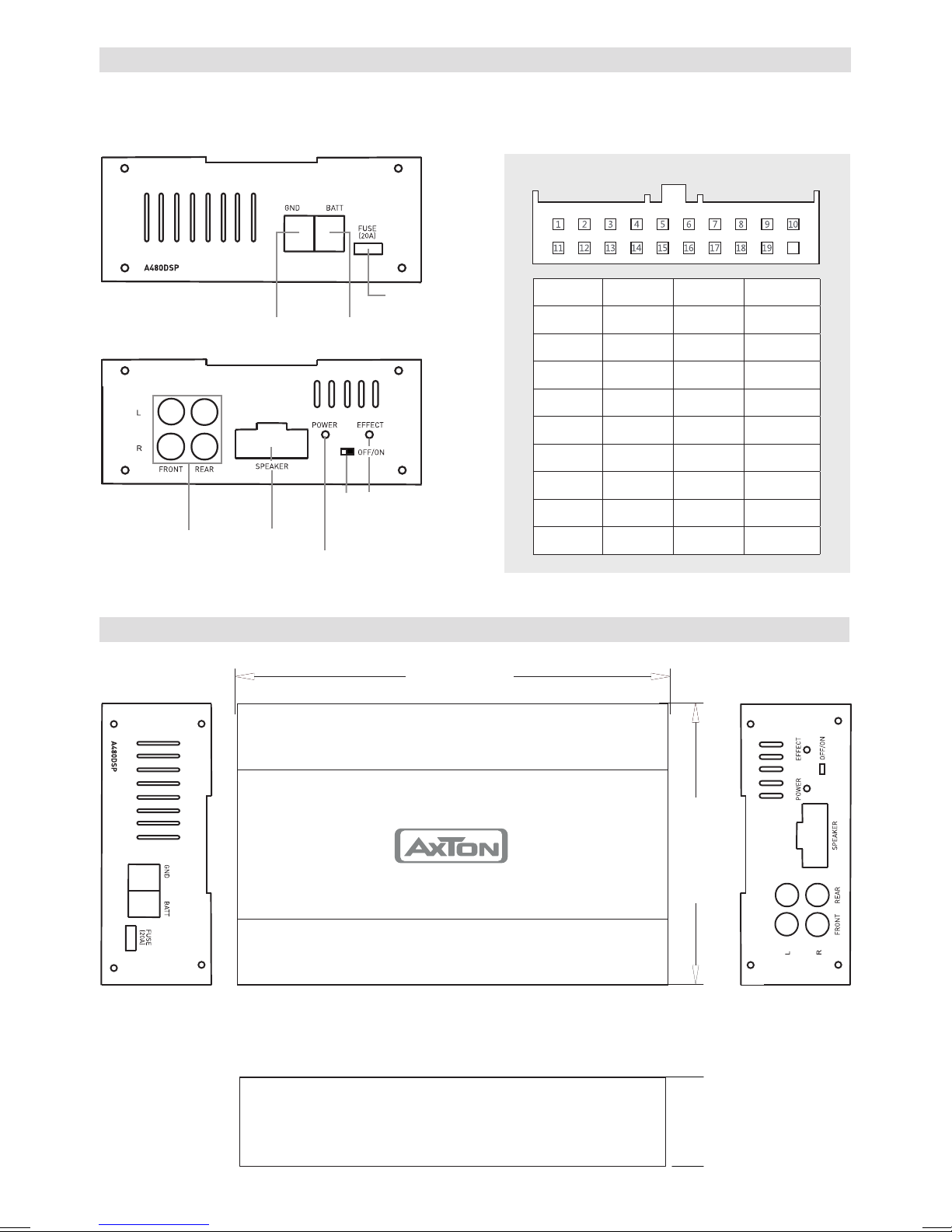
WIRING DIAGRAM
(30A)
If you want to use just the DSP function of the A480DSP with a separate high performance
amplifier, connect the line out of the A480DSP with the RCA input of your amplifier.
SPEAKER
20
LINE OUT
DIMENSIONS
GROUND (-)
SPEAKERFRONT/REAR
BATTERY (+)
DSP EFFECT
ON/OFF
POWER LED
FUSE
152 mm
1 11 GND
2 12 +B
3
4
5
6
7
8
9
RR-in
RR+in
RL-in
RL+in
FL-in
FL+ in
FR-in
13
14
15
16
17
18
19
FL+ ou t
FL-out
FR+out
FR-out
RL+o ut
RL-out
RR+out
10 FR+in 20 RR-out
132 mm
52 mm
– 6 –
 Loading...