

Page 1
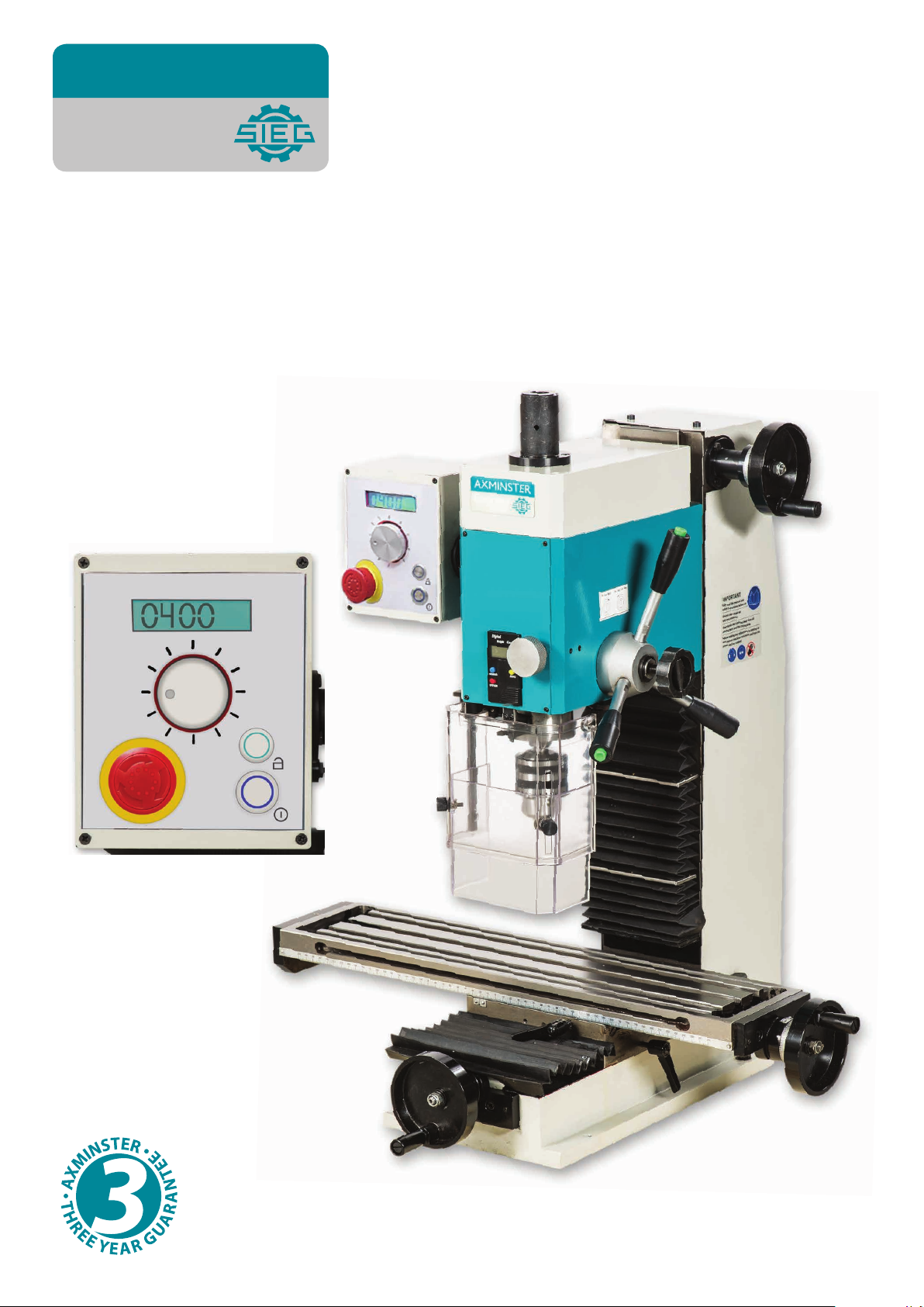
AXMINSTER
Engineer
SERIES
SX2.7
Mill Drill
Code 107154
Original Instructions
AT: 29/04/2021
BOOK VERSION: 3
Page 2
Cert No: SX2.7
EU Declaration of Conformity
Axminster Tool Centre Ltd
Axminster Devon
EX13 5PH UK
axminstertools.com
declares that the machinery described:-
Type Mill Drill
Model SX2.7
Signed
Andrew Parkhouse
Operations Director
Da te: 10/04/2020
This machine complies with the following directives:
2006/42/EC
2014/30/EU
EN 61000-3-2: 2014
EN 61000-3-3:2013
EN 55014-1:2017
EN 55014-2: 2015
and conforms to the machinery example for which the
EC Type-Examination Certificate No TA 385203412
has been issued by Shangjai SIEG Machinery Co., Ltd
at: No.555 CaoFeng Rd., South to No. 17 Bridge of Caoan Rd., SHANGHAI CHINA
and complies with the relevant essential health and safety requirements.
Page 3

2
IMPORTANT SAFETY INSTRUCTION
READ ALL INSTRUCTIONS AND WARNINGS BEFORE USING THIS TOOL
Operator
COMMON SENSE AND CAUTION ARE FACTORS WHICH CANNOT BE BUILT INTO
ANY PRODUCT. THESE FACTORS MUST BE SUPPLIED BY THE OPERATOR.
PLEASE REMEMBER:
1. When using electric tools, machines or equipment, basic safety precautions should
always be followed to reduce the risk of fire, electric shock, and personal injury.
2. Keep work area clean. Cluttered areas invite injuries.
3. Consider work area conditions. Do not use machines or power tools in damp, wet, or
poorly lit locations. Do not expose equipment to rain, keep work area well lit. Do not
use tools in the presence of flamable gases or liquids.
4. Keep children away, all children should be kept away from the work area.
5. Guard against electric shock. Prevent body contact with grounded surfaces such as
pipes, radiators, ranges, and refrigerator enclosures.
6. Stay alert. Never operate if you are tired.
7. Do not operate the product if under the influence of alcohol or drugs. Read warning
labels on prescriptions to determine if your judgment or reflexes might be impaired.
8. Do not wear loose clothing or jewelry as they can be caught in moving parts.
9. Wear restrictive hair covering to contain long hair.
10.Use eye and ear protection. Always wear.
11. Keep proper footing and balance at all times.
12.Do not reach over or across running machines.
Before operations
1. Be sure the switch is OFF when not in use and before plugging in.
2. Do not attempt to use inappropriate attachments in an attempt to exceed the tool”s
capacity. Approved accessories are available from the dealer or machine maker.
3. Check for damaged parts, before using any tool, any part that appears damaged
should be carefully checked to determine that it will operate properly and perform its
intended function.
4. Check for alignment and binding of all moving parts, broken parts or mounting fixtures
and any other condition that may affect proper operation. Any part that is damaged
should be prop early repaired or replaced by a qualified technician.
5. Do not use the tool if any switch does not turn off and properly
Operation
1. Never force the tool or attachment to do the work of a larger industrial tool. It is
designed to do the job better and more safely at the rate for which it was intended.
2. Do not carry the tool by its power cord.
3. Always unplug the cord by the plug. Never yank the cord out of the wall.
4. Always turn off the machine before unplugging.
Page 4

3
IF THERE IS ANY QUESTION ABOUT A CONDITION BEING SAFE OR UNSAFE,
Max. drilling capacity:
20 mm
Max. tapping capacity:
12 mm
End mill capacity
16 mm
Face mill capacity
50 mm
Throat
190 mm
Max. distance spindle to table
370 mm
Spindle taper
Choice of MT#3 or R8
Spindle speed
100-2000 rpm ±10%
Table effective size
T-slot size
12 mm
Table longitudinal travel (X)
400 mm
Cross travel (Y)
190 mm
Headstock travel (Z)
290 mm
Power
750 W
Overall dimension (L*W*H)
Packing size (L*W*H)
Weight (Net/Gross)
111 / 145 Kg
DO NOT OPERATE THE TOOL!
Grounding Instructions
This machine has a three-prong plug, the third prong is the ground. Plug this cord
only into a three-prong receptacle. Do not attempt to defeat the protection the ground wire
provides by cutting off the round prong. Cutting off the ground will result in a safety hazard
and void the warranty.
DO NOT MODIFY THE PLUG IN ANY WAY. IF YOU HAVE ANY DOUBT, CALL A
QUALIFIED ELECTRICIAN.
Specification:
595 x140 mm
825 x 620m x 880 mm
960 x 760 x 1060 mm
Unpacking & Preparing for Use
Before unpacking you must check the package carefully, to find whether it is damaged
and any may have effect on the machine, please connect with the distributor in advance.
Unpacking carefully, check the species of standard accessories and the quantity to find
whether it is as same as the packing list in the package.
Page 5
4
Product selection instructions:
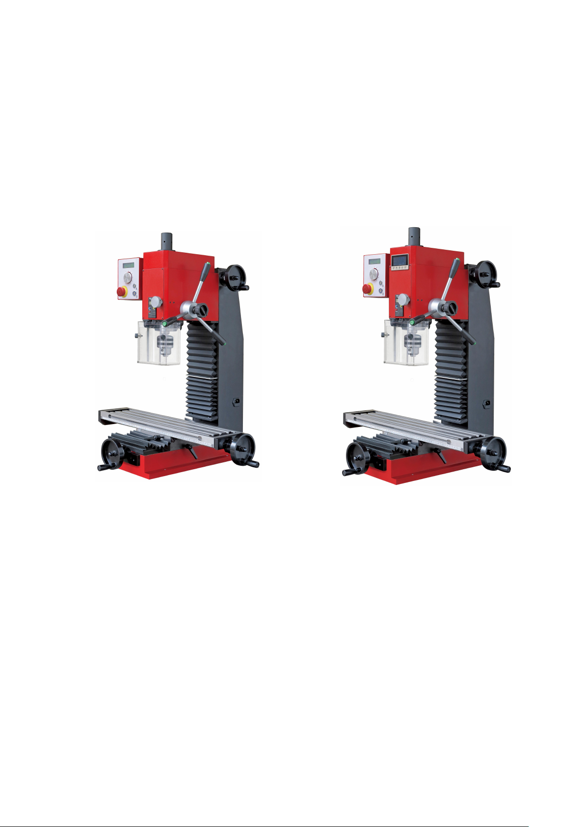
The SX2.7 Bench mil drill have different models to choose for you, the standard model we
call it name is SX2.7, you can add digital readout display the model name is SX2.7D
( you can see have a display in front of the head-stock)。
The “D” means with “3 axis display”; use three axis magnetic grating ruler+Digital readout
display.
Model SX2.7 picture Model SX2.7D picture
The main features and advantages of this product
1, The highest speed arrange 2000 rpm; variable spindle speed;
2, Spindle speed digital readout;
3, Tapping function;
4, Brush less DC motor;
5, Chuck guard with safety switch ( optional );
6, Feeding depth digital readout;
7, Fine feeding;
8, With two USB sockets, can supply power to Lamp or IPAD;
9, Large size worktable 700*160mm;
Page 6
5
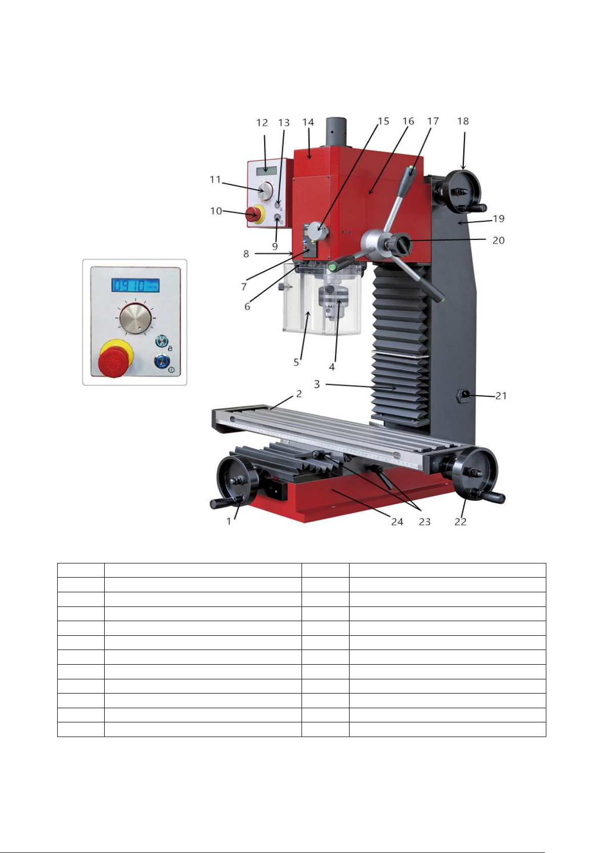
FEATURE / Model SX2.7
1
Y- axis handwheel
2
Work tabel
3
Column (with protect cover)
4
Drill chuck with arbor
5
Protective guard assembly
6
Micro switch assembly
7
Depth display (spindle travel)
8
Screw for lock the spindle sleeve
9
On/Off button
10
Emergency stop switch
11
Variable speed control knob
12
Spindle speed display
13
Tapping choose button
14
Spindle box cover
15
Fine feeding handle
16
Spindle box
17
Control handle with tapping button
18
Z-axis handwheel
19
Back cover (PC Board inside)
20
Fine feeding locking knob
21
Power socket with fuse box
22
X-axis handwheel
23
Locking handle assembly
24
Base
Page 7
6
Installation
305
2 1 0
CAUTION!
DO NOT ATTEMPT TO USE THE MACHINE UNTIL INSTALLTION IS CAMPLETED,
AND ALL PRELIMINARY CHECKS HAVE BEEN MADE IN ACCORDANCE WITH THIS
MANUAL.
MOUNTING THE MACHINE
The machine should be mounted on a strong, heavy workbench, of sufficient height so
that you do not need to bend your back to perform normal operations.
Ensure the location is adequately lit and that you will not be working in your own shadow.
We strongly recommend that the machine bolted firmly to strong workbench using the
tapped holes used to secure the feet to the machine. This is to provide added stability and
consequently, additional safety.
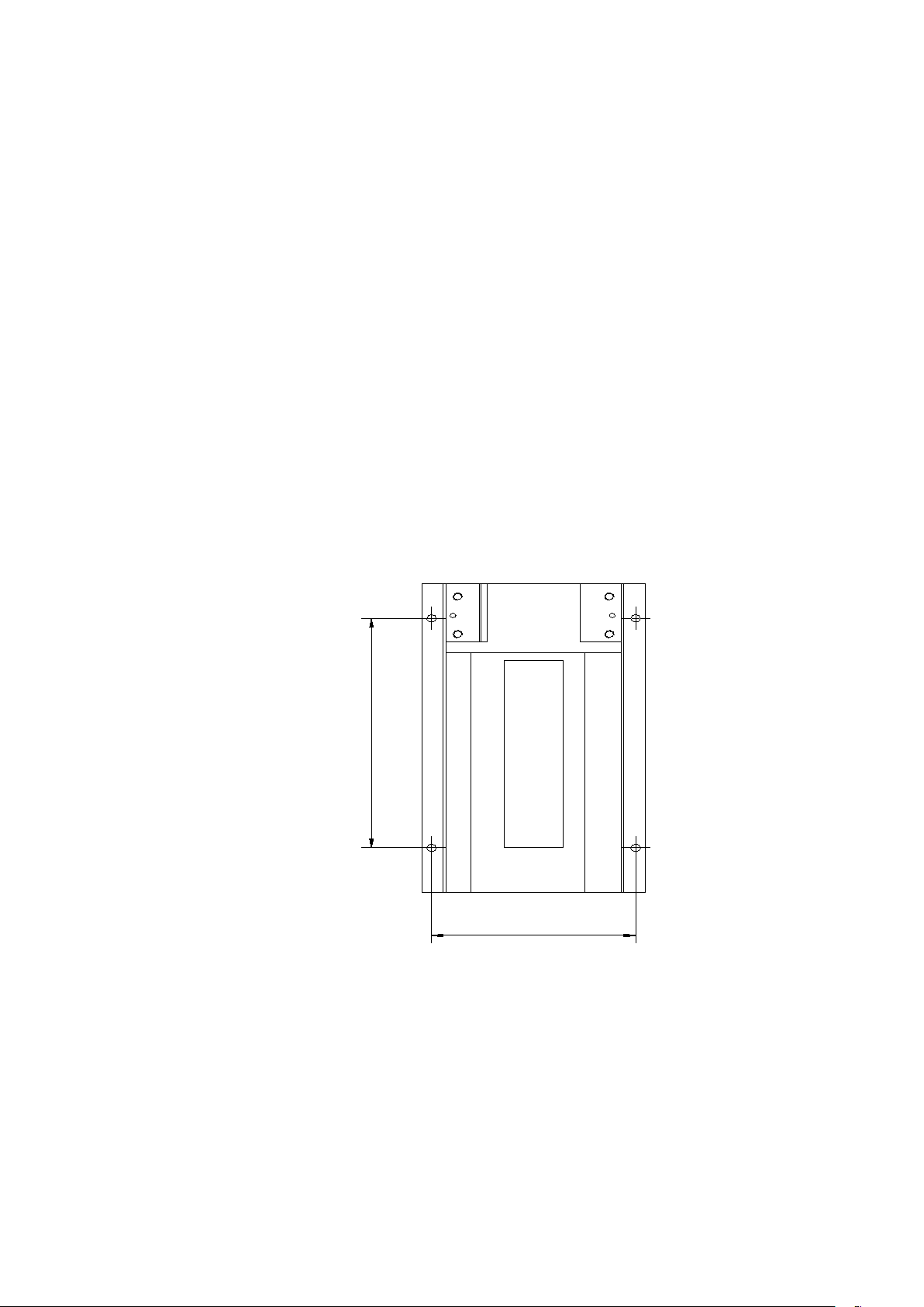
To do this, first drill four M12 clearance holes in a worktop, at the dimensions
shown in the diagram opposite, and with appropriate length M8 bolts, or screws,
with flat washers. (not supply, you need prepare these by yourself).
Application
This small mill machine is both for milling or drilling and tapping, widely used in different
places. Fine exterior, wide range of speed and easy to use.
Designed for industrial usage milling, drilling, tapping, reaming, steps and mill plane with
metal and other material.
Page 8
7
Operation
controls and also the driving systems.
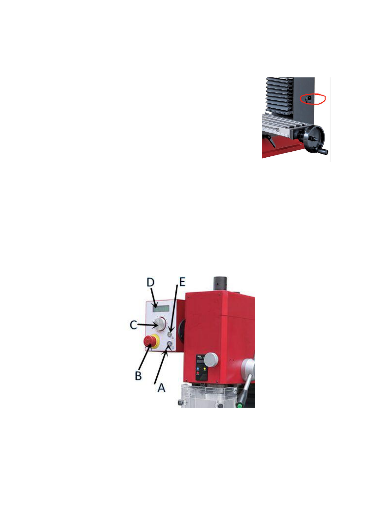
(1) Insert the power line insert the socket right of the
fuselage, then power on;
1. Before starts to use this machine, operator should go through the instructions carefully
so as to acquaint with the construction of the machines, the functions of the various
(2) Loosen the emergency stop switch (B), then the spindle speed display (D) bright
and show “0000”, press the start button (A) then clockwise rotation of the speed control
button (C), can make the spindle speed raise to the highest position. Under these
circumstances the mill only have forward direction. Under tapping circumstances have
forward and reverse direction. Press the tapping function lock button (E), then is button
will bright, then you can press a green button to choose the spindle run to forward or
reverse. The green button total 3 pcs, they on the right of the spindle box in the lifting
lever. You can see the word of forward or reverse on the right of the display (D), it easy to
show the user the direction of the rotation of the spindle.
Notice:
(1) In general, it is only in an emergency that a snap stop switch is needed to stop the
spindle from turning. Do not often use the emergency stop switch (B) stop the machine, it is
bad to the main PC Board.
(2) After using should turn the power switch to position ‘0’ and press the emergency
stop switch (B), then pull out the power plug from socket.
Page 9
8
Several characteristic functions
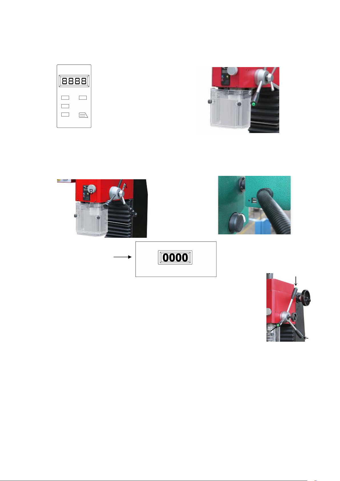
6. Tapping: the highest speed under ‘Tapping mode’ is 500rpm. Press the
button end of the handle the first is “forward” when press again it change
to “reverse”. Notice it have three handle all can control so it is very easy
to do.
See the picture on the right position.
1. Spindle depth display 2. Chuck guard with safety switch
3. Spindle fine feeding ( tighten the lock knob
“A” then turn the fine feeding knob “B”. 4. Two USB sockets, can supply power
5. Spindle speed readout
Brief introduction of conventional mechanical operation ( Picture for
reference only)
1. The clamping tool and work piece must stop the machine first;
2. Clean the inner hole of the spindle and the conical surface of the tool rod, push the tool
rod into the inner hole of the spindle, and put in the pull rod to hang the tool rod;
3. The parts to be processed are placed on the surface of the worktable. After pressing
with the pressing plate or use vice clamped, the parts are moved to the desired position
vertically and horizontally.
Page 10
9
4. Loosen the column lock handle, shake the lift handle and move the spindle box down;
5. Start the machine, select a good rotation speed, turn counterclockwise to turn the
lifting handle, and drilling of milling can be done at this time;
6. When milling parts, we must lock the spindle box and spindle, at the same time lock
the longitudinal transverse plug iron according to the need, so as not to change the
machining size;
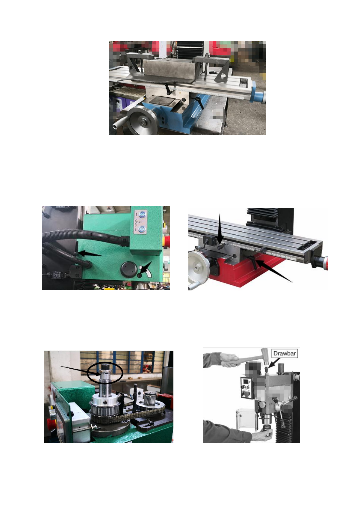
7. When replacing the drill chuck or milling chuck, open the top shield loosely on the
edge, loosen the screw thread of the pull rod 2-3 teeth, then use a hammer to knock the
taper handle away from the main shaft, and finally loosen the handle with the hand to
replace the rod.
Page 11
10
After using
After the completion of the work, the power supply should be cut off, the machine tool and
environment should be cleaned well, and mechanical oil should be added to the exposed
surface of the machine to prevent the surface of the machine from rusting and affecting
the use and beauty of the machine.
Machine tool lubrication
In order to ensure the long service life of the machine and the effective operation of the
machine tool, lubricating oil or lubricating oil is regularly added to each moving joint and
joint.
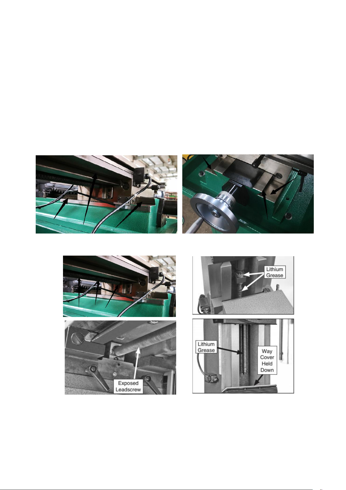
Where lubricating oil is needed is mainly the dovetail surface in three directions of XYZ
axis.(Position as indicated by arrow)
The main ones that need to be lubricated are XYZ's three axial thread rods and rod nuts.
Page 12

11
Common trouble problems and their Solutions
Symptom
Possible Cause
Possible Solution
Motor can not
start
1. The power supply is not on.
2. Low voltage.
3. Motor open circuit or loose
connection.
4. The external input socket is
broken.
5. May which switch is bad or
connect line loosen;
1. Turn on the emergency stop button
2. Check that the voltage of the power
supply is correct.
3. Check that all the connections of the
motor are loosened or disconnected.
4. Check and confirm the input socket is
ok.
5. Check switch and the connect lines is
tighten.
Fuse or circuit
breaker
disconnected
1. Wire or plug short circuit
2. Circuit board short circuit
3. Power supply fuse or circuit
breaker incorrect.
1. Check wires and plugs for damaged or
missing insulation and replace them with
extension wires.
2. Check the voltage of the power supply
is correct
3. Check that all connections of the motor
are loose or welded or insulated, and
replace the correct fuse or circuit breaker
in time
Motor
overheating
1. Motor overload
2. Air circulation of motor is
restricted
1. Reduce the load of motor
2. Clean the motor and ensure smooth
circulation of air
The hand wheel
of a transverse
or feed trawl is
too loose
1. The adjusting screw is not in
place.
2. Hand wheel loosened
3. Wire rod assembly old or not
in place
1. Tighten the adjusting screw and
lubricate the bed
2. Tighten the hand wheel knob
3. Tighten all loose knobs on the thread
rod assembly.
The machine
makes constant
noise
1. The gear or bearing is out of
order.
2. The motor is out of order.
1. Replace damaged gear or bearing
2. Replace motor
During
operation, the
machine stops
1. Drilling and milling too deep
2. The wrong speed or feed
speed was used in the drilling
and milling operation.
3. Milling cutter damage
4. Motor damaged
5. Gear damaged
1. Reduce drilling depth
2. Choose the right speed
3. Replacement milling cutter
4. Replacement motor
5. Replacement gear
Finish surface
difference
1. Speed or feed speed error
2. Milling cutter broken or
wrong selected
1. Change the milling cutter by adjusting
the correct speed or feed speed
2. Change the cutter
Difficult to move
the end part on
the guide rail
1. Drying of guideway
2. Z shaft hand wheel to tighten
3. Over compacted with debris
on guide rail
1. Lubricating oil
2. Adjusting screw
3. Cleaning guide
T - type nut is
difficult to fix
1. T type nut defect or damaged
2. T-groove on the wrong
working table
1. Replacement of type T nut
2. Replacement of table or well-used T
slot
Page 13
12
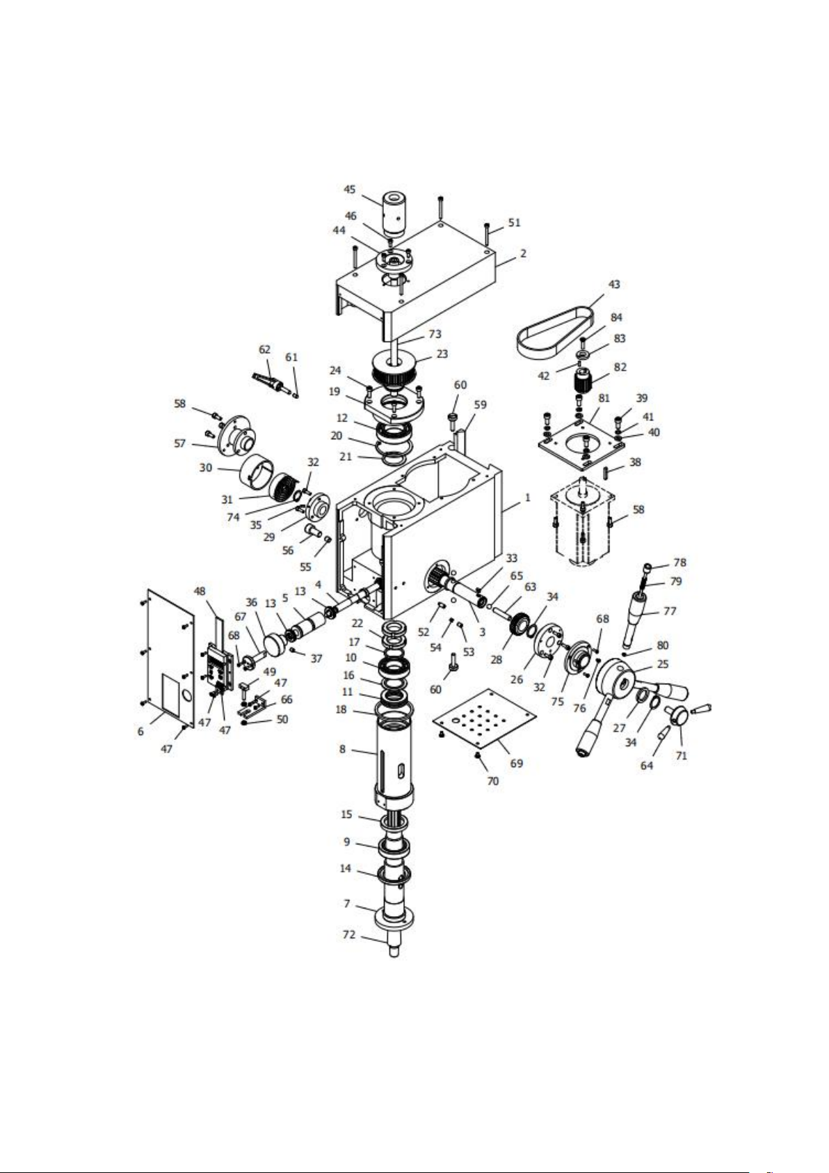
Parts drawing (I)
Page 14

13
Parts list (I)
No.
drawing No.
description
Q'ty
I-1
LXN3A02B01
Spindle box
1
I-2
LXN3A02B02
Spindle box cover
1
I-3
LXN3A02B03
Gear shaft
1
I-4
LXN3A02B04
Worm shaft
1
I-5
LXN3A02B05
Worm eccentric sleeve
1
I-6
LXN3A02B07A
Panel (standard)
1
LXN3A02B07
Panel use for DRO
LXN3A02B0700
Panel use for Mobile
I-7
LX3C0212
MT3 Spindle
1
LX3C02A01
R8 Spindle
I-8
LX3C0213
MT3 Spindle sleeve
1
LX3C02A02
R8 Spindle sleeve
I-9
GB/T 297-94 - 32907
Cone roller bearing 32907
1
I-10
GB 278-89 - 80106
Deep groove ball bearing 80106
1
I-11
GB 301-84 - 8106
Thrust ball bearing 8106
1
I-12
GB 278-89 - 80107
Deep groove ball bearing 80107
1
I-13
7_70 - 12 x 22 x 5
Thrust ball bearing 12*22*5
2
I-14
LX3C0219
Spindle below oil seal ring I
1
I-15
LX3C0216
Spindle sleeve below oil seal ring II
1
I-16
LX3C0210
Up washer II
1
I-17
LX3C0209
Up washer
1
I-18
LXN3A0226
Sleeve limit washer
1
I-19
LXN3A02B08
Bearing seat
1
I-20
GB 893.1 - 62
Check ring 62
1
I-21
GB 894.1 - 35
Check ring 35
1
I-22
GB 810-88 - M27x1.5
Slotted round nut M27*1.5
2
I-23
LX3C0206
Spindle timing pulley
1
I-24
GB 70-85 - M5 x 16
Screw M5*16
4
I-25
LXN3B0202
Handle seat
1
I-26
LXN3B0204
Shaft gear right support flange
1
I-27
LXN3A0222
Adjust washer
1
I-28
LXN3A0210
Bevel gear
1
I-29
LX3C0252
Shaft gear left support flange
1
I-30
LX3C0253
Clock spring cover
1
I-31
LXN20243
Clock spring
1
I-32
GB 70-85 - M4 x 12
Screw M4*12
6
Page 15

14
I-33
GB1096-79 4x8
Flat key 4*8
1
I-34
GB 894.1 - 20
Check ring 20
2
I-35
GB 879-86 - 3 x 8
Spring pin 3*8
1
I-36
LXN3A0218
Fine feed handwheel
1
I-37
GB 77-85 - M6 x 6
Screw M6*6
1
I-38
GB1096-79 4x25
Flat key 4*25
1
I-39
GB 70-85 - M6 x 14
Screw M6*14
4
I-40
GB 97.1-85 - 6
Washer 6
4
I-41
GB 93-87 - M6
Spring washer 6
4
I-42
GB 119-86 - A 3 x 10
Spring pin 3*10
1
I-43
HTD-5M 385(77 齿)
Timing belt 385 (Z77)
1
I-44
X3C0220
Spindle up dust guard I
1
I-45
X3C0265
Spindle up dust guard II
1
I-46
GB 70-85 - M4 x 10
Screw M4*10
3
I-47
GB 818-85 - M3 x 8
Screw M3*8
14
I-48
GD300-165
Display assembly GD300-165
1
I-49
LX3C0217
Square screw
1
I-50
GB 6172-86 - M5
Nut M5
2
I-51
GB 70-85 - M4 x 40
Screw M4*40
4
I-52
GB 79-85 - M6 x 14
Screw M6*14
1
I-53
GB 77-85 - M6 x 8
Screw M6*8
1
I-54
LXN3A0216
Eccentric sleeve locking block
1
I-55
LXN3A0208
Spindle sleeve lock shaft
1
I-56
GB 70-85 - M10 x 20
Screw M10*20
1
I-57
LXN3A0211
Connect support
1
I-58
GB 70-85 - M5 x 12
Screw M5*12
7
I-59
LXN3A0202
Bevel wedge
1
I-60
LXN3A0223
Wedge screw
2
I-61
LXN3A0217
Tighten the top rod
1
I-62
LX20218B00
Small handle assembly
1
I-63
LXN3A02B06
Lock shaft
1
I-64
LX3.50208
Small handle
2
I-65
GB308-89 - 8
Ball 8
3
I-66
LX3.50209
Display assembly support
1
I-67
LX3.50217
Shuttle
1
I-68
GB 819-85 - M3x10
Screw M3*10
5
I-69
LXN3B0209
Base plate
1
I-70
GB 818-85 - M4 x 6
Screw M4*6
2
I-71
LX3.50207
Lock top shaft
1
Page 16
15
I-72
LX20206
B16 taper shank
1
LX302A04
JT6 taper shank
I-73
LX3C021100
Lifting bolt assembly
1
I-74
GB 894.1 - 16
Check ring 16
1
I-75
LSX2.30201
Conductive ring assembly
1
I-76
GB 818-85 - M3 x 4
Screw M3*4
1
I-77
LXN3B020700
Control handle assembly
3
I-78
LXN3B020800
F/R control pole assembly
3
I-79
GB2089-80 0.8x6x25
Compress spring 0.8*6*25
3
I-80
GB 896-86 3
Spring washer 3
3
I-81
LXN3B0203
Motor support plate
1
I-82
LXN3B0201
Motor timing pulley
1
I-83
LXN3B0205
Washer
1
I-84
GB 819-85 - M5x20
Screw M5*20
1
I-85*
LX3C02A03
Key use for R8 spindle
1
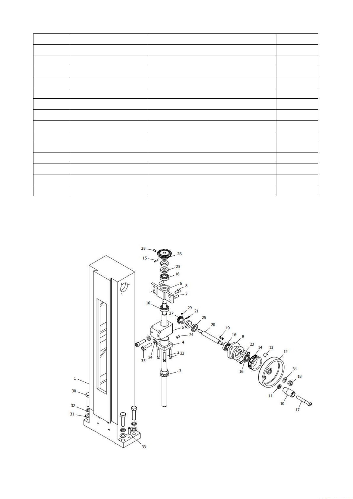
Parts drawing (2)
Page 17

16
Parts list (2)
No.
Drawing No.
Description
Q'ty
.2-1
LXN3A0901
Column
1
.2-2
LXN3A0903A
Metric rise and down leadscrew
1
LXN3A0903B
Inch rise and down leadscrew
.2-3
LXN3A0908A
Metric rise and down locking nut
1
LXN3A0908B
Inch rise and down locking nut
.2-4
LXN3A0907A
Metric rise and down leadscrew nut
1
LXN3A0907B
Inch rise and down leadscrew nut
.2-5
LXN3A0904
Column nut support
1
.2-6
LXN3A0911
Leadscrew support
1
.2-7
GB 118-86 - 6 x 16
Taper pin 6*16
2
.2-8
GB 70-85 - M6 x 12
Screw M6*12
2
.2-9
LXN3A0910
Rise and down support seat
1
.2-10
L'C2A0307
Handle
1
.2-11
GB 6172-86 M8
Hex nut M8
1
.2-12
LX3111800
Handle wheel
1
.2-13
LX31145
Spring piece
1
.2-14
LXN3A0909A
Metric rise and down scale dial
1
LXN3A0909B
Inch rise and down scale dial
.2-15
GB 879-86 - 3 x 20
Spring round pin 3*20
1
.2-16
GB/T 276-94 - 6001
Deep groove ball bearing 6001
4
.2-17
GB 65-85x55
Screws 8*55
1
.2-18
GB 889-86 M8
Hex locking nut M8
1
.2-19
GB1096-79 4x16
Parallet key 4*16
1
.2-20
LXN3A0902
Rise and down shaft
1
.2-21
GB 879-86 - 3 x 16
Spring round pin 3*16
1
.2-22
GB 70-85 - M5 x 30
Screw M5*20
4
.2-23
GB 5781-86 - M5x16
Bolt M5*16
3
.2-24
GB 77-85 - M6 x 10
Screw M6*10
1
.2-25
LXN3A0912
Locking nut
4
.2-26
LXN3A0914
Big bevel gear wheel
1
.2-27
LXN3A0913
Small bevel gear wheel
1
.2-28
GB 78-85 - M5 x 8
Screw M5*8
1
.2-29
GB 78-85 - M5 x 5
Screw M5*5
1
.2-30
GB 5780-86 - M10x40
Bolt M10*40
4
.2-31
GB 97.1-85 - 10
Washer 10
4
.2-32
GB 859-87 - 10
Spring washer 10
4
.2-33
GB 118-86 - 6 x 24
Taper pin 6*24
2
.2-34
GB 97.1-85 - 8
Washer 8
1
.2-35
GB 70-85 - M8 x 30
Screw M8*30
2
Page 18
17
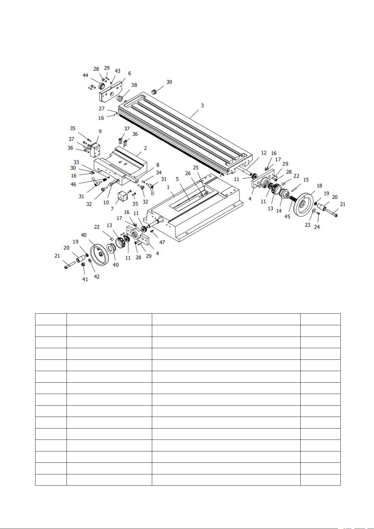
Parts drawing (3)
No.
Drawing No.
Description
Q'ty
.3-1
LXN3A1101B
Base
1
.3-2
LXN3A11A03A
Saddle
1
.3-3
LXN3A11A02B
Work table
1
.3-4
LXN3A1108
leadscrew bearing seat
2
.3-5
LXN3A11A04
Metric cross leadscrew
1
LXN3A11A04A
Inch cross leadscrew
.3-6
LXN3A1106
Left end cover
1
.3-7
LXN3A1107A
Metric cross leadscrew nut
1
LXN3A1107B
Inch cross leadscrew nut
.3-8
LXN3A1111
Longitudinal bevel wedge
1
.3-9
LXN3A1113A
Metric longitudinal leadscrew nut
1
LXN3A1113B
Inch longitudinal leadscrew nut
.3-10
LXN3A11A05
Cross bevel wedge
1
.3-11
GB 301-84 - 8101
Thrust ball bearing 8101
4
Parts list (3)
Page 19

18
.3-12
LXN3A11A01
Metric longitudinal leadscrew
1
LXN3A11A01A
Inch longitudinal leadscrew
.3-13
LXN3A1112A
Metric dial ring
2
LXN3A1112B
Inch dial ring
.3-14
LX31142
Leadscrew clutch
1
.3-15
GB 117-86 - A 4 x 28
Round taper pin 4*28
1
.3-16
GB827-86 2x4
Sign rive 2*4
8
.3-17
LX21118
Indicator
2
.3-18
LX3C1105
Longitudinal leadscrew handwheel
1
.3-19
GB 6172-86 M8
Nut M8
2
.3-20
LC2A0307
Handle
2
.3-21
GB65-85 M8x55
Screw M8*55
2
.3-22
LX31145
Spring piece
2
.3-23
LGT20017
Washer
1
.3-24
GB 70-85 - M4 x 10
Screw M4*10
1
.3-25
GB 70-85 - M6 x 10
Screw M6*10
1
.3-26
GB 96-85 - 6
Washer
1
.3-27
LXN3A11A06
Scale ruler
1
LXN3A11A06A
Inch scale ruler
.3-28
GB 70-85 - M6 x 16
Screw M6*16
6
.3-29
GB 119-86 - A 4 x 20
Round pin 4*20
6
.3-30
LC5C0315
0 position label
1
.3-31
LX2021800
Small handle assembly
2
.3-32
LXN3A0223
Wedge screw
4
.3-33
LXN3A0217
Lock top bar
1
.3-34
LXN3A1109
Longitudinal wedge lock top bar
1
.3-35
GB 70-85 - M4 x 14
Screw M4*14
4
.3-36
GB 70-85 - M5 x 20
Screw M5*20
4
.3-37
GB 117-86 - A 3 x 30
Round taper pin 3*30
4
.3-38
LX31131
Left sleeve
1
.3-39
LX31144
End cap
1
.3-40
LX3111800
Handwheel assembly
1
.3-41
GB 889-86 M8
Lock nut M8
1
.3-42
GB 97.1-85 - 8
Washer
1
.3-43
JBT7940.4-95 6
Cylinder oil cup 6
1
.3-44
LX31136
End cap of left support
1
.3-45
LXN3A11A07
Compress spring
1
.3-46
GB2089-80 1x9.2x14
Compress spring 1*9.2*14
1
.3-47
GB1096-79 4x16
Flat key 4*16
1
Page 20
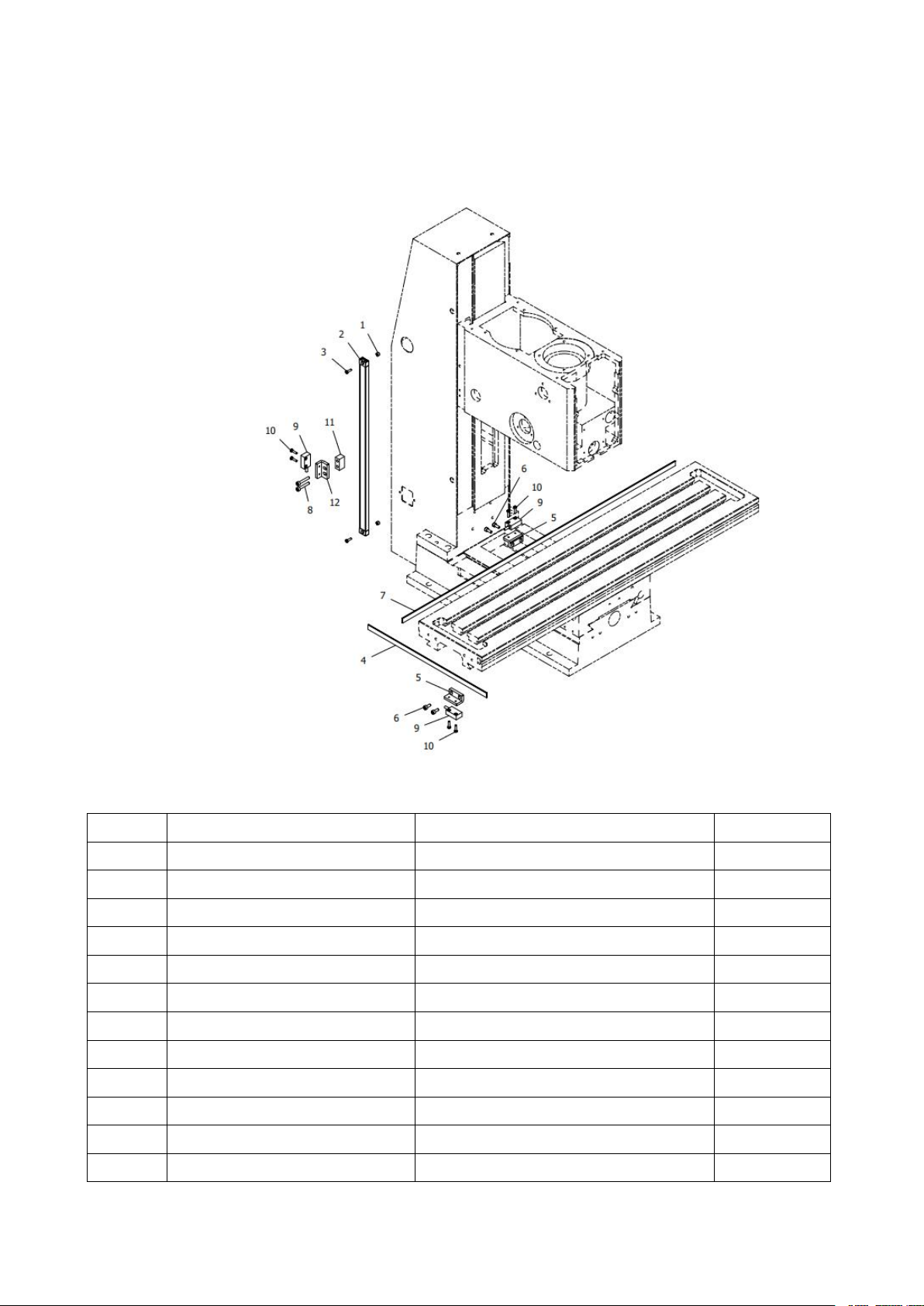
19
Parts drawing (3A)
No.
Drawing No.
Description
Q'ty
.3A-1
LX2.31004
Washer
2
.3A-2
LX21001A00
X axis magnetic ruler assembly
1
.3A-3
GB 818-85 - M3 x 10
Screw M3*10
2
.3A-4
LX3.51001
X axis magnetic ruler
1
.3A-5
LXN3A10B01
Reader support
2
.3A-6
GB 70-85 - M4 x 10
Screw M4*10
4
.3A-7
LXN3A10A01
X axis magnetic ruler
1
.3A-8
GB 70-85 - M4 x 25
Screw M4*25
2
.3A-9
MG10V
DRO with readers assembly
3
.3A-10
GB 818-85 - M3 x 12
Screw M3*12
6
.3A-11
LX21005
Reader block
1
.3A-12
LXN3A10B02
Z axis reader block
1
Notice: this drawing is follow the SX2.7D Mill. The “D” means with “3 axis display”; use
MG10V three axis magnetic grating ruler+Digital readout display.
Parts list (3A)
Page 21
20
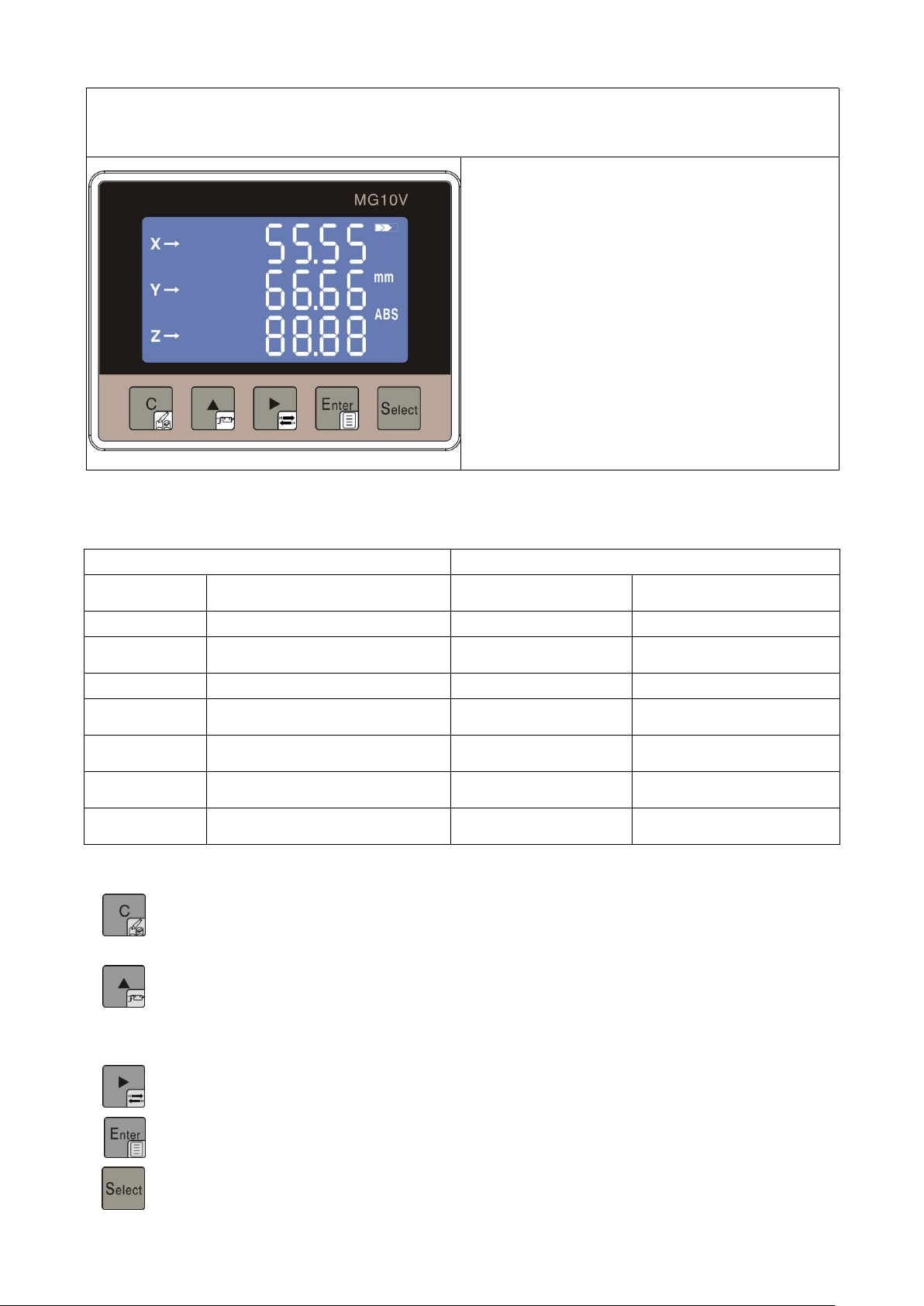
Magnetic Grid Digital Display MG10V User Manual
(
This is the optional function, only on “D” type had
)
New features description
Icon mode defines common function
shortcuts (modify current value,
repair&redirection, sensor adaptive mode)
Fully aluminum alloy shell structure design,
Ultra strong anti-interference ability.
Pluggable docking power supply,
communication, sensor (air plug optional)
connection.
High-end smart LCD VI reverse color display
Four-point self-expansion damping type
convenient installation method.
One table three display (S, Y, Z), three-axis
measurement display.
Specifications / Performance
Long press (4s): modify key / modify current value
Function status short press: clear or exit the current interface / relative mode clear key
Long press (4s): sensor adaptive calibration mode
Function status short press: modify the current display parameters, normal short press: relative /
Long press (4s): change the sensor increment direction
Function status short press: switch key / / parameter shift
Long press (4s): enter the menu
Short press: modify confirmation button
Short press: X, Y, Z, select button
Electrical performance
Mechanical behavior
System
accuracy
±(0.03+0.01*L) L Unit: m
Maximum appearance
size
96*72*46.5mm
Repeatability
Max.±0.01mm
Hole Size
91.5*65.5mm ±1
Resolution
0.01、0.05、0.1、1
Read head line length
Default 1M (Line length can
be customized)
Display range
-999999~999999
Read head gap
Standard 1~2mm
Current
consumption
Max.400uA(LED not lit)
Moving speed
Max.5m/s
Built-in battery
One 2nd battery (excessive
standby)
Matching magnetic ruler
TR50 /5mm+5mm
External power
supply
DC (12v~24v)
Operating
temperature
-20℃ ~ 70℃
Key Description
absolute mode switching
Page 22
21
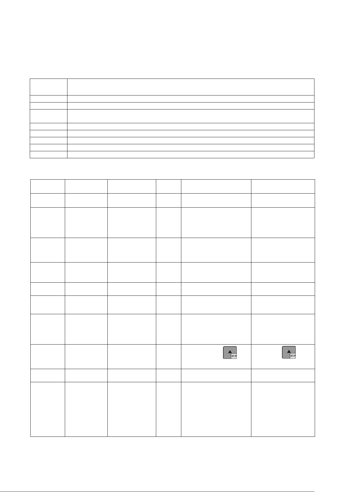
Tips: Please pay attention to the small icons on the buttons and understand the meaning
Error
message
Information description
E01
Parameter input error
E06
Sensor failure: 1: sensor damage; 2: sensor cable is damaged;
E07
Magnetic stripe detection failed: 1: no magnetic strip; 2: magnetic strip is damaged; 3: reading
head is too far away from the magnetic strip
E08
Battery is too low, it is recommended to replace the battery immediately
E09
The read head is too close to the tape
E10
The read head is too far from the tape
E12
No battery, no battery installed in the digital display
E20
The measured value is out of the display range
Numbering
Function
description
Parameter
Default
s
Parameter description
Remarks
P01,P31,
P61
Measurement
unit switching
Length / Angle
0
0:Length mode
1:Angle mode
After modification, press
"Enter" to confirm
P02,P32,
P62
Current value
setting or (via
shortcut)
-999999~~99999
9
0
Save the input value as the
current value
Enter the password
before modification:
1234
After modification, press
"Enter" to confirm
P03,P33,
P63
Measuring
direction or (via
shortcut)
0~110 or 1 represents two
directions
Change the direction of
the sensor and also
change the direction of
measurement
P04,P34,
P64
Length
resolution
0,1,2,3,4
4
0:INCH 1:1
2:0.1 3:0.05
4:0.01
After modification, press
"Enter" to confirm
P06,P36,
P66
Scale factor
0.00001~2.99999
1
Display value = measure
true value * scale factor
After modification, press
"Enter" to confirm
P08,P38,
P68
Concentric
diameter
0.01~9999.99
500.00
The diameter of the disc to
which the magnetic strip is
attached
Diameter needs to add
magnetic strip thickness
1.5mm*2mm=3MM
P09,P39,
P69
Angle
resolution
0.01 degree 0.01
points
0.05 points 0.1
points
1 degree
0.01de
gree
Sufficient under angle
mode
After modification, press
"Enter" to confirm
P10,P30,
P60
Absolute/Relati
ve mode
0:unlock
1:lock
0
By releasing the key
Shortpress key to
change mode
P28,P58,
P88
Reset
None
None
Restore default factory
settings
Enter password before
recovery:1234
P07,P37,
P67
Adaptive
calibration (or
via shortcuts)
GO
GO
GO:Enter the state, slowly
move (can be moved
repeatedly) sensor, move
150MM in about 10
seconds, automatically
jump to the current value
state after learning success
If the calibration is not
successful, please
adjust the distance
between the sensor and
the magnetic stripe. It is
recommended to be
1~~2MM.
Repeat the operation
again
of the icons, which will make the operation of the digital display faster and easier.
Display Description
Parameter Description
Page 23
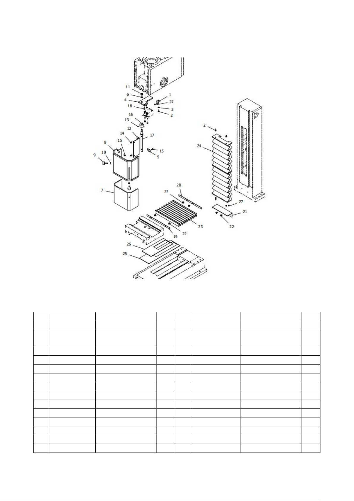
22
Parts drawing (4)
No.
Drawing No.
Description
Q'ty
No.
Drawing No.
Description
Q'ty
.4-1
LX12304
Block
1
.4-15
GB 819-85 - M4x10
Screw M4*10
3
.4-2
GB 818-85 - M4 x
10
Screw M4*10
3
.4-16
LX3C23C05
Spacer bush
1
.4-3
GB 97.1-85 - 4
Washer 4
1
.4-17
LX3C23C02
Rotate shaft
1
.4-4
LXN3A23A01
Support plate
1
.4-18
GB 70-85 - M4 x 12
Screw M4*12
2
.4-5
LXN3A23A02
Back plate
1
.4-19
LX20002
Strip
1
.4-6
GB 97.1-85 - 6
Washer 6
1
.4-20
LX20004
Strip
1
.4-7
LX3C23C0401
Inner protect guard
1
.4-21
LXN3A2303
Block
1
.4-8
LX3C23C03
Outside protect guard
1
.4-22
GB 818-85 - M5 x 6
Screw M5*6
6
.4-9
GB 835-88 - M5x20
Knurled screw M5*20
2
.4-23
LX20003
Dust guard
1
.4-10
GB 97.1-85 - 5
Washer 5
2
.4-24
LXN3A2302
Guideway protect cover
1
.4-11
GB 889-86 - M6
Lock nut
1
.4-25
LXN3A2305
Finder block I
1
.4-12
LX3.52311
Support
1
.4-26
LXN3A2304
Finder block II
1
.4-13
GB 78-85 - M4 x 6
Screw M4*6
1
.4-27
YE023003
Φ6 magnetic steel
5
.4-14
GB 818-85 - M4 x 8
Screw M4*8
2
Parts list (4)
Page 24
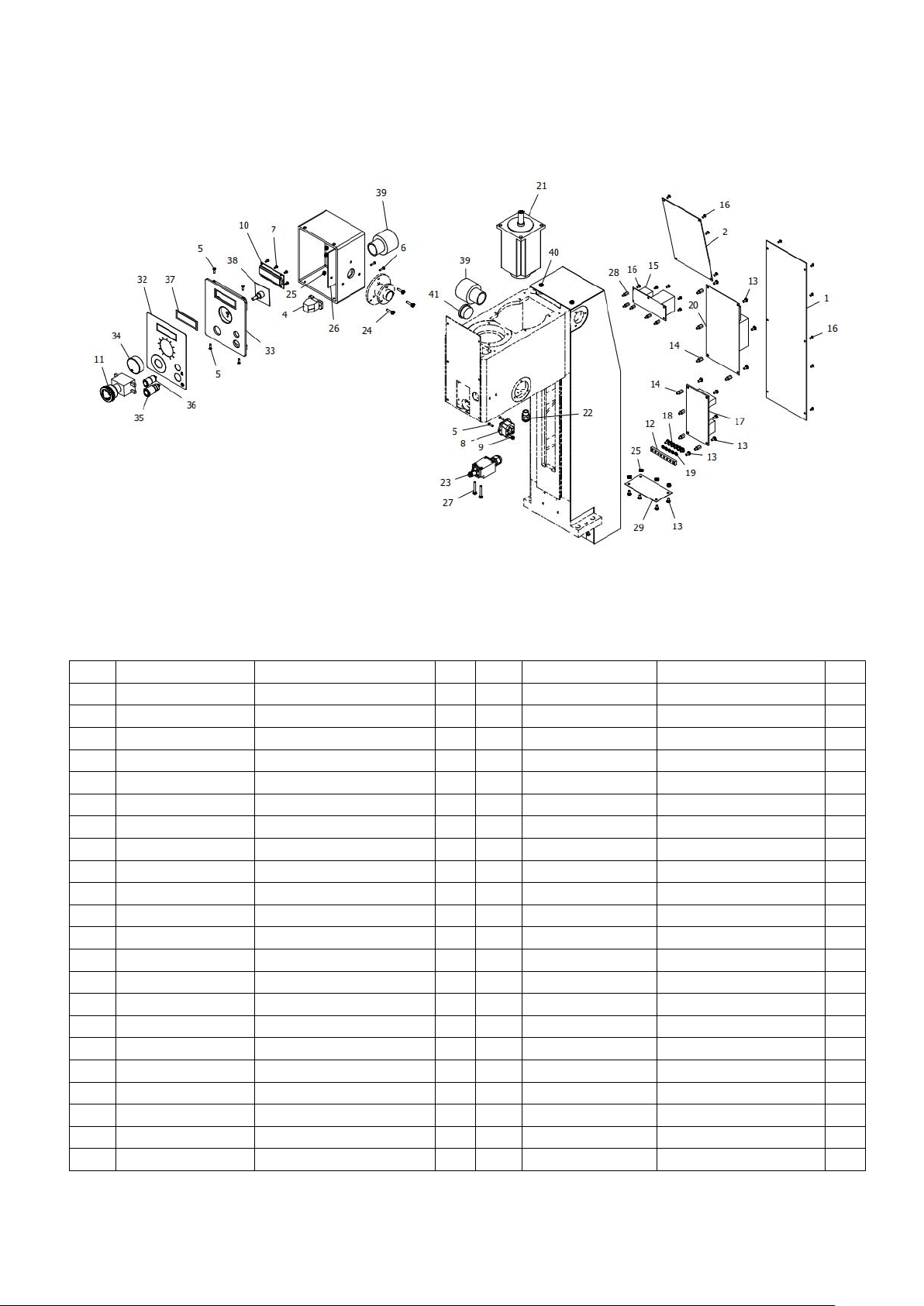
23
Parts drawing (5) ----Standard Electrical type
No.
Drawing No.
Description
Q'ty
No.
Drawing No.
Description
Q'ty
.5-1
LXN3A1804
Lower cover
1
.5-21
W80-750A /230V
W80-750A Brushless motor
1
.5-2
LXN3A1805
Upper cover plate
1
.5-22
M12
M12 draw lock
1
.5-3
LXN3A18D0200
Rear hood assembly
1
.5-23
QKS7
QKS7 Safety limit switch
1
.5-4
USB
USB socket assembly
1
.5-24
GB 5783-86 - M4 x 16
Bolt M4*16
3
.5-5
GB 819-85 - M3x12
Screw M3*12
6
.5-25
GB 6170-86 - M4
Nut M4
7
.5-6
GB 818-85 - M3 x 12
Screw M3*12
2
.5-26
LX351803
Electrical box linings
1
.5-7
GB 845-85 - ST2.9 x 6.5
Screw ST2.9*6.5
4
.5-27
GB 818-85 - M4 x 30
Screw M4*30
2
.5-8
DB-14F
DB-14F fuse holder
1
.5-28
HTS-310
HTS-310 Lsolation pillar
5
.5-9
GB 6170-86 - M3
Nut M3
2
.5-29
LX3C1806
Lower dust screen
1
.5-10
Y-2
Y-2 Liquid crystal board
1
.5-30
LX3C23C01
Shoe plate
1
.5-11
HY57B
HY57B Emergency stop switch
1
.5-31
LX351801
Electric Box
1
.5-12
LX3C1802
Grounding row
1
.5-32
LSX352511
Switch sign
1
.5-13
GB 818-85 - M4 x 8
Screw M4*8
14
.5-33
LSX351801
Electric box cover
1
.5-14
HTS-410
HTS-410 Lsolation pillar
8
.5-34
GX-2
GX-2 Knob
1
.5-15
ZD-2
DC power supply board 230V
1
.5-35
J19-271B
J19-E-271B Start-stop button
1
ZD-2
DC power supply board 110V
.5-36
J16-E-271B
J16-E-271B Tapping button
1
.5-16
GB 818-85 - M3 x 6
Screw M3*6
15
.5-37
LSX351802
Back plate
1
.5-17*
XMT-2305L
Filter (only use for 230V)
1
.5-38
X-4D
X-4D Knob panel
1
.5-18
GB 818-85 - M5 x 6
Screw M45*6
5
.5-39
WQG-M32B/AD34.5
Fast hose connector
2
.5-19
GB 93-87 - M5
Spring washer 5
5
.5-40
GB/T 818 M5 x 8
Screw M5*8
4
.5-20
Z750-1A
Z750-1A/230V PC Board
1
.5-41
DPK-M30B
Nylon Stuffing Cover
1
Z750-1A
Z750-1A /110V PC Board
Parts list (5)
Page 25
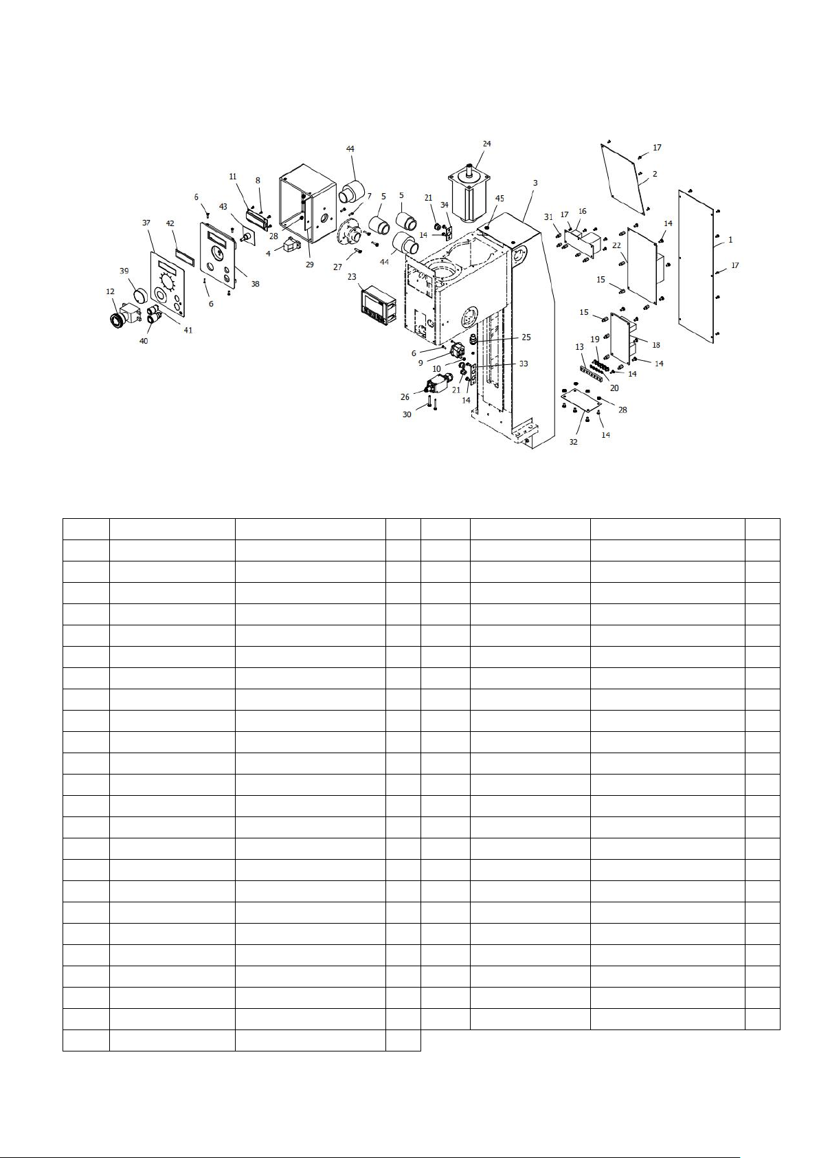
24
Parts drawing (5A) ----With “Display kit” Electrical type
No.
Drawing No.
Description
Q'ty
No.
Drawing No.
Description
Q'ty
.5A-1
LXN3A1804
Lower cover
1
.5A-23
MG10V
MG10V Display
1
.5A-2
LXN3A1805
Upper cover plate
1
.5A-24
W80-750A
W80-750A Brushless motor
1
.5A-3
LXN3A180300
Rear hood assembly
1
.5A-25
M12
M12 draw lock
1
.5A-4
USB
USB socket assembly
1
.5A-26
QKS7
QKS7 Safety limit switch
1
.5A-5
WQG1-M30B/AD28.5
Fast hose connector
2
.5A-27
GB 5783-86 - M4 x 16
Bolt M4*16
3
.5A-6
GB 819-85 - M3x12
Screw M3*12
6
.5A-28
GB 6170-86 - M4
Nut M4
11
.5A-7
GB 818-85 - M3 x 12
Screw M3*12
2
.5A-29
X3.51803
Electrical box linings
1
.5A-8
GB 845-85 - ST2.9 x 6.5
Screw ST2.9*6.5
4
.5A-30
GB 818-85 - M4 x 30
Screw M4*30
2
.5A-9
DB-14F
DB-14F fuse holder
1
.5A-31
HTS-310
HTS-310 Lsolation pillar
5
.5A-10
GB 6170-86 - M3
Nut M3
2
.5A-32
LX3C1806
Lower dust screen
1
.5A-11
Y-2
Y-2 Liquid crystal board
1
.5A-33
LX351813A
Wire clip holder
1
.5A-12
HY57B
Emergency stop switch
1
.5A-34
LXN3A18B02
Wire clip holder
1
.5A-13
LX3C1802
Ground row
1
.5A-35
LX3C23C01
Shop plate
1
.5A-14
GB 818-85 - M4 x 8
Screw M4*8
18
.5A-36
LX351801
Electric box
1
.5A-15
HTS-410
HTS-410 Lsolation pillar
8
.5A-37
LSX352511
Swicth sign
1
.5A-16
ZD-2/230V
Power supply board
1
.5A-38
LSX351801
Electric box cover
1
ZD-2/110V
Power supply board
.5A-39
GX-2
GX-2 Knob
1
.5A-17
GB 818-85 - M3 x 6
Screw M3*6
15
.5A-40
J19-271B
J19-E-271B Start-stop button
1
.5A-18
XMT-2305L
Filter (only for 230V)
1
.5A-41
J16-E-271B
J16-E-271B Tapping button
1
.5A-19
GB 818-85 - M5 x 6
Screw M5*6
5
.5A-42
LSX351802
Back plate
1
.5A-20
GB 93-87 - M5
Spring washer 5
5
.5A-43
X-4D
X-4D Knob panel
1
.5A-21
6W2
Wire buckle
3
.5A-44
WQG-M32B/AD34.5
Fast hose connector
2
.5A-22
Z750-1A/230V
ZD750-1A/230V PC Board
1
.5A-45
GB/T 818 M5 x 8
Screw M5*8
4
Z750-1A/110V
ZD750-1A/110V PC Board
Parts list (5A)
Page 26
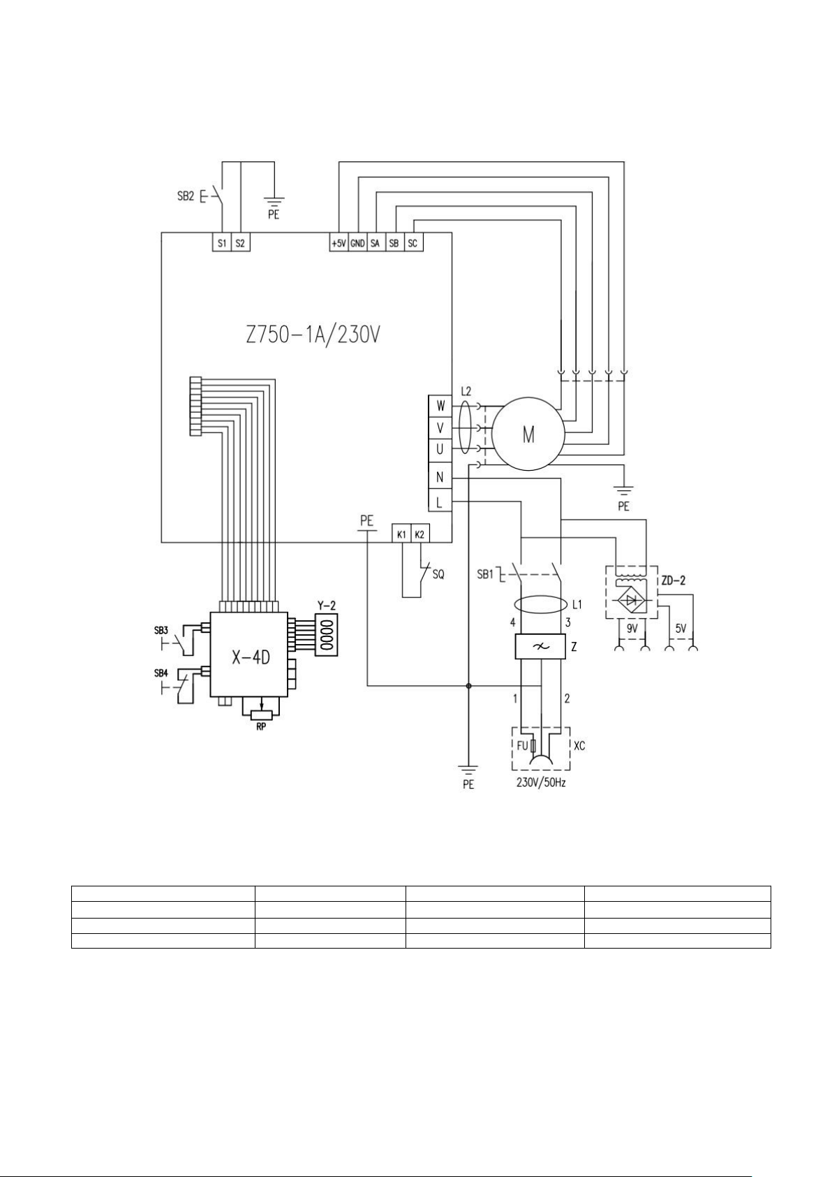
25
SX2.7 MILL Electrical wiring diagram
Z750-1A/230V: PC Board
M1: Brushless motor
ZD-2: DC power supply plate
FU: Fuse (8A/230V, 15A/110V)
X-4D: Knob panel
SB2: Tapping button
Z: Filter (only use on 230V)
XC: Socket with fuse
SB1: Emergency stop switch
Y-2: Liquid crystal board
SQ: Micro switch
SB3: Start/stop button
L1: Magnet ring /only on 230V
L2: Magnet ring
SB4: Tapping button
Page 27
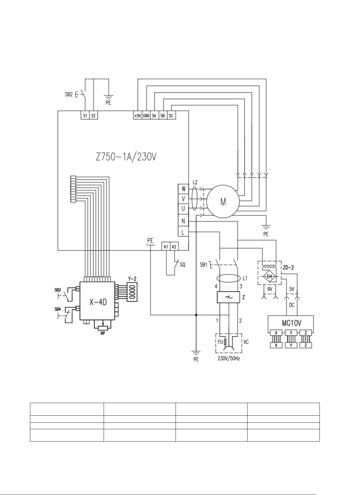
26
SX2.7D MILL Electrical wiring diagram
Z750-1A/230V: PC Board
M1: Brushless motor
ZD-2: DC power supply
plate
FU: Fuse (8A/230V,
15A/110V)
X-4D: Knob panel
SB2: Tapping button
Z: Filter (only use on 230V)
XC: Socket with fuse
SB1: Emergency stop switch
Y-2: Liquid crystal board
SQ: Micro switch
SB3: Start/stop button
L1: Magnet ring (only on
230V)
L2: Magnet ring
MG10V: Display
SB4: Tapping button
Page 28
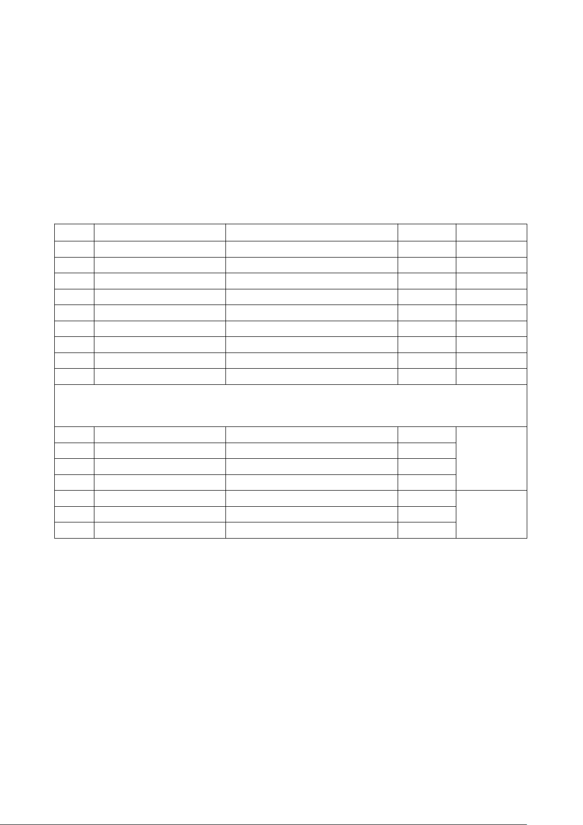
27
Packing List
No.
Name
Description
Q'ty
Remarks
1
Bench Mill
type: X2.7 or SX2.7
1 set
2
Fuse
110V/20A or 230V/10A
1 pce.
3
Manual
manual
1 pce.
4
Double end wrench
S1*S2: 8*10、14*17、17*19
each 1
5
L hex wrench
S: 3、4、5、6、8
each 1
6
U wrench assembly
X3C004
1 pce.
7
Oil cup
1 pce.
8
T nut
X22001
2 pcs.
9
L hex wrench assembly
X3C2003
1 件
Below parts usually fixed on the machine (According to choice of MT3 or R8)
10*
B16 drill chuck
J2113/ 1-13mm / B16
1 pce.
MT3 type
11*
MT3 taper shank
X20206
1 pce.
12*
locking bolt assembly
X3C021100(X3C021101)
1 pce.
13*
slanting wedge
X3C2002
1 pce.
14*
JT6 drill chuck
3-16mm / JT6
1 pce.
R8 type
15*
R8 taper shank
X302A04(A)
1 pce.
16*
locking bolt assembly
X3C021101B (7/16")
1 pce.
Page 29

The Axminster guarantee is available on
Craft, Trade, Engineer, Air Tools & CNC Technology Series machines
Buy with confidence from Axminster!
So sure are we of the quality, we cover all parts and labour free of charge for three years!
For more information visit axminstertools.com/3years
The packaging is suitable for recycling.
Please dispose of it in a responsible manner.
EU Countries Only
Do not dispose of electric tools together with household waste material.
By law they must be collected and recycled separately.
Axminster Tools, Axminster Devon EX13 5PH
axminstertools.com
 Loading...