

Page 1
Product
Instructions
25734
C O M M U N I C A T I O N S
Before attempting to connect or operate this product,
please read these instructions completely.
81-IN6215
06/01/07
Page 2
!
!
1. Read Instructions - All the safety and operating instructions
should be read before the unit is operated.
2. Retain Instructions - The safety and operating instructions
should be retained for future reference.
3. Heed Warnings - All warnings on the unit and in the operating
instructions should be adhered to.
4. Follow Instructions - All operating and user instructions should
be followed.
5. Electrical Connections - Only a qualied electrician should make
electrical connections.
6. Attachments - Do not use attachments not recommended by
the product manufacturer as they may cause hazards.
7. Cable Runs - All cable runs must be within permissible
distance.
8. Mounting - This unit must be properly and securely mounted to
a supporting structure capable of sustaining the weight of the
unit. Accordingly:
a. The installation should be made by a qualied installer.
b. The installation should be in compliance with local codes.
c. Care should be exercised to select suitable hardware to
install the unit, taking into account both the composition of
the mounting surface and the weight of the unit. Be sure to
periodically examine the unit and the supporting structure to
make sure that the integrity of the installation is intact. Failure
to comply with the foregoing could result in the unit separating
from the support structure and falling, with resultant damages
or injury to anyone or anything struck by the falling unit.
WARRANTY INFORMATION
Videolarm, Incorporated warrants that products sold hereunder
shall be t for the ordinary purpose for which said products
are intended and shall be free from defects in material and
workmanship for a period of two years from date of sale to
buyer. Videolarm makes no other warranty of any kind with
respect to this product, whether expressed or implied, including,
without limitation, the implied warranty of tness for a particular
purpose.
In the event of a breach of the above warranty, Videolarm shall,
at its option, repair or replace said product. This is Videolarm's
sole obligation under this warranty. In no event shall Videolarm
be liable for any incidental or consequential damages, as dened
in section 2-715 of the Uniform Commercial Code by a breach
of this warranty.
Videolarm shall repair or replace defective products upon shipment
of products prepaid to Videolarm, Inc., 2525 Park Central Blvd.,
Decatur, GA 30035.
SAFETY PRECAUTIONSIMPORTANT SAFEGUARDS
CAUTION
RISK OF
ELECTRIC SHOCK!
CAUTION: TO REDUCE THE RISK OF
ELECTRICAL SHOCK, DO NOT EXPOSE
COMPONENTS TO WATER OR MOISTURE.
The lightning ash with an arrowhead symbol,
within an equilateral triangle, is intended to alert the
user to the presence of non-insulated "dangerous
voltage" within the product's enclosure that may
be of sufcient magnitude to constitute a risk of
electric shock to persons.
The exclamation point within an equilateral
triangle is intended to alert the user to presence of
important operating and maintenance (servicing)
instructions in the literature accompanying the
appliance.
UNPACKING
Unpack carefully. Electronic components can be damaged if
improperly handled or dropped. If an item appears to have been
damaged in shipment, replace it properly in its carton and notify
the shipper.
Be sure to save:
1. The shipping carton and packaging material. They are the safest
material in which to make future shipments of the equipment.
2. These Installation and Operating Instructions.
SERVICE
If the unit ever needs repair service, the customer should contact
Videolarm (1-800-554-1124) for authorization to return and shipping
instructions.
TECHNICAL SUPPORT
If technical support is needed, Videolarm has set-up a 24 hour
technical support line for their customers.
Repairs made necessary by reason of accident, misuse or normal
wear shall be charged at Videolarm's standard rate. This warranty
gives you specic legal rights, and you may also have other rights
which vary from state to state.
24 HOUR TECHNICAL SUPPORT
1-800-554-1124
- 2 -
Page 3
!
!
ELECTRICAL SPECIFICATIONS (OUTDOOR ONLY):
Power 24VAC, Class 2 Only
52 watts at 24 VAC (accessories)
Heater: 50 watts
Blower: 2 watts
NOTE: This unit is designed for operation in an
upright position. Installing the unit upside
down may cause damage to the internal
equipment, and will void the warranty.
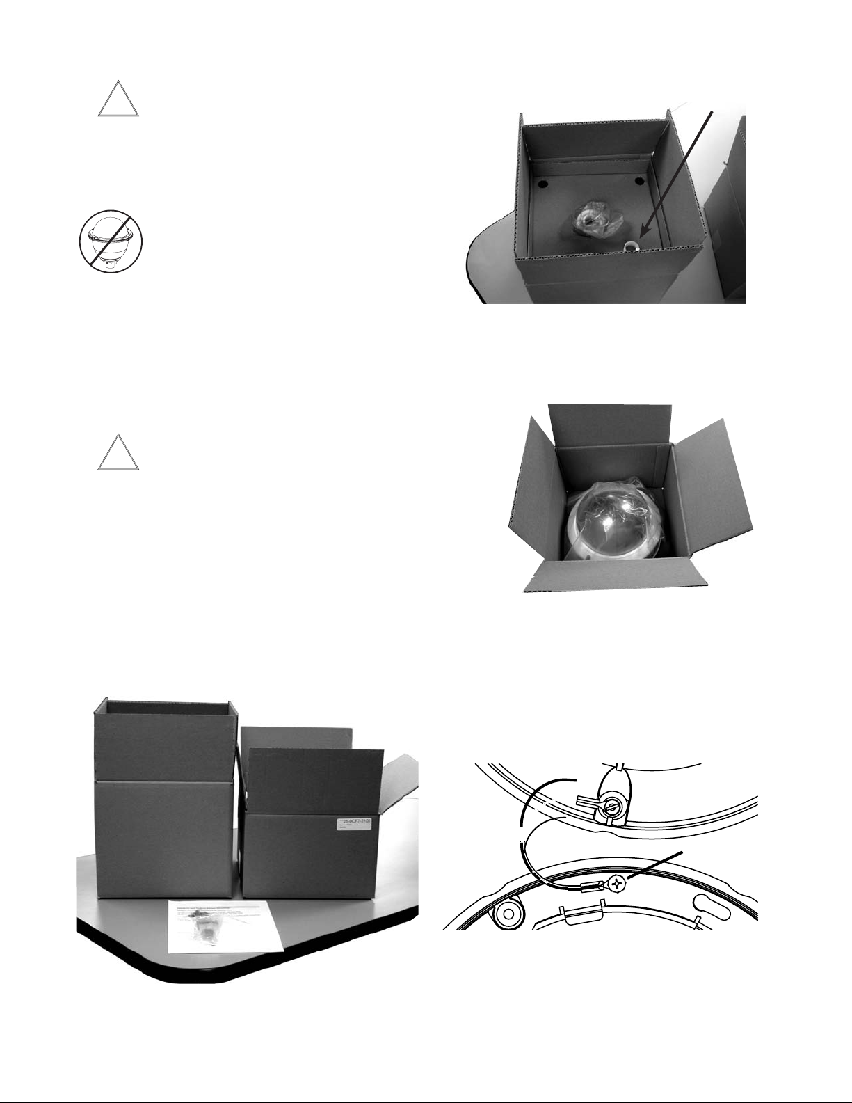
2. Open the housing assembly box. Note there is a small roll
of Teon Tape that will be needed during installation, put it
aside. (Picture 2)
Teon Tape
Picture 2
GENERAL INSTRUCTIONS:
Tools Required: .100" Flat Head Screwdriver
Phillips Head Screwdriver
Be sure the bracket is properly and securely
mounted to a supporting structure capable of
rigidly holding the weight of the entire unit.
ASSEMBLING THE PRODUCT:
1. Remove the contents of the box onto a table. The larger
subassembly box is the housing assembly. The smaller
subassembly box is the dome assembly. (Picture 1)
Picture 1
3, Open the dome assembly box. Note there is a protection
lm on the dome. DO NOT REMOVE the lm until the
product is fully assembled and installed. This lm protects
the dome from scratches during installation. (Picture 3)
Picture 3
4. There is a safety lanyard that is attached to the inside of
housing assembly. Remove the phillips head screw on the
trim ring assembly and then attach the lanyard to the trim
ring with the phillips head screw.
5. The safety lanyard is now attached to the housing
(Picture 5).
the
Attach Lanyard
to Trim Ring
Picture 5
Listed on the following pages are the specic instructions
for each of the individual network cameras. See specic
instruction for the model that matches the unit you have.
- 3 -
Page 4
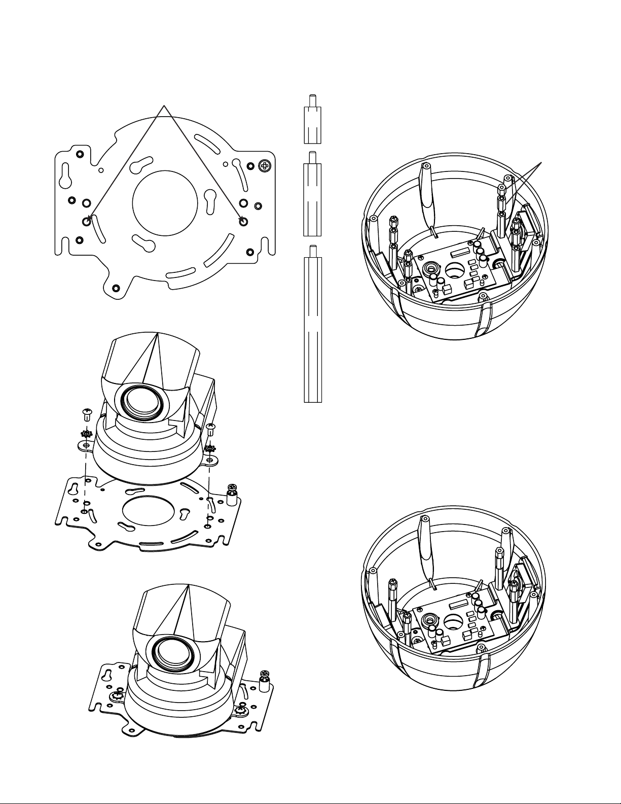
Installing the Axis 213 Camera
1. Install the camera onto the quick release bracket using
(2) 10-32 x 3/8” screws and star washers provided in the
packet.
Attach cameras using these (2) holes
½"
1"
2"
2. In the kit there are (8) aluminum spacers - (4) 1" and
(4) ½". Thread (2) spacers - (1) 1" and (1) ½" - on
top of each of the (4) 2" spacers that are already
located on the base bracket inside the housing.
½" + 1" spacers
3. Then start (3) 8-32x3/8” phillips head screws onto the
3½ inch spacers inside the housing. Be sure to place
the screws so that they line up with the (3) open slots
on the quick release bracket.
- 4 -
Page 5
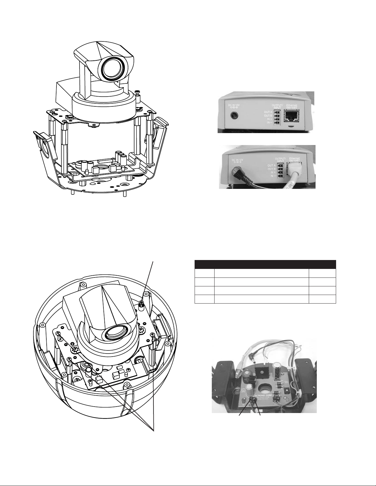
Installing Axis 213 Camera (cont.)
CAMERA POWER
Connect the power plug and the ethernet cable to the back
of the camera.
4. Mount the camera assembly in the housing, sliding
the (3) open screw slots over the (3) screws in the
housing. Slide the bracket forward then tighten the
captive screw on the bracket.
Captive Screw
CONTROL
RJ45 Ethernet Connector
ALARMS
1 Alarm 1 Blue
2 Alarm 2 Violet
3 Alarm 3 Gray
4 Common White
Power Connection - Reference
Only
(3) screws
in housing
+12 VDC -12 VDC
- 5 -
Page 6

Installing Axis 214 Camera
Attach cameras using these (3) holes
1"
3. Place (3) 8 x 32 x s Phillips head screws on the top
of the spacer as shown above. Be sure to place the
screws so that they line up with the open slots on the
mounting plate.
4. Slide the mounting plate with camera into position on
top of spacers. Secure 3 screws and captive fastener.
1. Install the AXIS 214 camera to the 2685 mounting
plate using the (3) 3mm x 12mm bolt and lock washers
provided.
2. The AXIS 214 camera requires 1” of spacing for optimal
position within the housing. Use the 4 (1”) spacers
provided in the packet.
- 6 -
Page 7

Installing Axis 231D/232D Camera
1. Install the camera onto the quick release bracket. Loosen
one of the screws on the bottom of the camera, see
diagram below.
Loosen screw
2. Place quick release bracket onto the bottom of the
camera, making sure that the (3) locking buttons line up
with the keyhole slots in the Q/R
bracket. Also make sure
the screw that
you loosened
up in the
previous
step lines
up with
the slot
located
next
to the
captive
insert.
Keyhole slots
Locking screw
Captive insert
Locking
buttons
4. When the locking buttons hit the end of the keyhole slots.
Tighten the locking screw. Then put the camera assembly
aside.
Locking screw
5. Since the 231D/232D camera operates on 24vac, the
power board that is located inside the housing is not
needed. The remove the power board, start by loosening
the screws on the terminal block and disconnect the
orange and red wires.
6. With a Phillips head screwdriver remove the (4) machine
screws holding the power board to the base bracket.
3. Turn the camera counter
clockwise.
Machine screws (4)
Base Bracket
- 7 -
Page 8

Installing Axis 231D/232D Camera (cont.)
7. Then start (3) 8-32x3/8” phillips head screws onto the (3) ½" spacers inside
the housing. Be sure to place the screws so that they line up with the (3)
open slots on the quick release bracket, the screws on the bottom of the
camera, see diagram below.
(3) 8-32 x 3/8"screws
8. Locate the connector block,
which is included with the
camera. Then located the
connector block bracket,
which is included with the
housing. Attach the block
to the bracket as shown
in the following diagram.
Use the M3 screws
and washers that are
located in the housing
packet.
9. Attach the connector
block assembly to the
housing using (1) 632x3/8” screw and star
washer located in the
housing packet.
10. Make wiring connections to connector block assembly per
camera instructions.
Wiring Connections
POWER
1 Camera Power (24VAC) Red
2 Camera Power (24VAC) Orange
CONTROL
RJ45 Ethernet Connector
ALARMS
1 Alarm 1 Blue
2 Alarm 2 Violet
3 Alarm 3 Gray
4 Common White
- 8 -
Page 9

Installing Axis 231D/232D Camera
(cont.)
11. To manage the input cable running from the connector
block to the camera use the (2) cable tie mounts and
cable ties that are located in the housing packet.
Cable Tie Mounts
13. Attach the
camera
assembly to
the housing by
sliding the (3)
open screw
slots over the
screws in the
housing. Slide
the bracket
forward, and
the tighten the
captive screw
on the bracket.
Captive screw
Cable Ties
12. Now grab the camera assembly and connector the RJ45
cable and the input cable to the camera.
Open screw slots
FOR REFERENCE ONLY
- 9 -
Page 10

Installing Axis 233 Camera
1. Note the position of the mounting holes on the camera
bracket (see diagram below).
Camera Bracket Mounting holes
Mounting holes for housing
2. Since the 233 camera operates on 24vac, the power
board that is located inside the housing is not needed.
The remove the power board, start by loosening the
screws on the terminal block and disconnect the
orange and red wires.
4. Now remove the Base Bracket.
3. With a Phillips head screwdriver remove the (4) machine
screws holding the power board to the base bracket.
Remove the power board.
Machine screws (4)
5. Now attach (4) 1” spacers (located in the packet that
came with the housing) to the base bracket.
Attach (4) 1" spacers
1"
Base Bracket
- 10 -
Page 11

Installing Axis 233 Camera (cont.)
6. Mount the Axis 233 camera bracket and Q/R plate (Quick
Release plate) as shown.
Keyhole SlotsQuick Release
(Q/R) plate
Keyhole Slots
7. Place the Quick Release plate onto the bottom of the
camera,
Make sure that the locking
screws on the AXIS 233
camera line up with
the keyhole slots
on the Q/R plate.
Slide the
camera into
the keyhole
slots by
targeting
the locking
screw(s).
Keyhole Slots
Locking Screw
8. Turn the camera counter-clockwise.
9. When the locking
buttons hit the end
of the keyhole
slots, tighten
the locking
screw.
- 11 -
Page 12

INSTALLING THE HOUSING ASSEMBLY:
!
REMOVING AND ATTACHING THE DOME ASSEMBLY:
Be sure the bracket is properly and securely
mounted to a supporting structure capable of rigidly
holding the weight of the entire unit.
NOTE: This unit is designed for operation in an
upright position. Installing the product upside
down may cause damage to the internal
equipment, and will void the warranty.
1. This unit includes a 1½" NPT housing for a standard 1½"
NPT pipe. The housing can be used with other brackets
designed with 1½" male pipe threads, such as the UNI-WMB1
wall mount brackets.
2. Attach the housing coupling (Figure 3).
NOTE: Pipe threads should be clean and rust free.
Use the Teon™ tape included with
the housing on the threads.
Add thread
sealing tape
1. Attach the dome assembly to the housing top by lining
up the three pins with the three keyhole slots. Insert the
dome assembly into the housing and then rotate the dome
assembly clockwise. Then tighten the (3) screws on the front
of the dome assembly.
Figure 3
3. Mount the housing assembly to the mounting bracket
and housing coupling. A safety cable is included with
the housing to temporarily hold it while making wiring
connections. Loop the safety cable over one of the set
screws on the housing coupling and make the appropriate
connections using the (2) screw-down connectors supplied.
2. Undo the safety cable and twist the housing onto the
housing coupling. Secure all (3) setscrews provided on the
housing coupling (Figure 4).
Set screws
Figure 4
2. Remove the protective
lm from the dome.
3. Clean the outside of
the dome.
Chart A Wiring Color Code
Power and Control Inputs
(Outside of housing)
POWER
1 Camera Power (24 VAC) Red
2 Camera Power (24 VAC) Orange
3 Accessory Power (24 VAC) Yellow
4 Accessory Power (24 VAC) Green
Separate Power Supplies for Camera and Accessory Power
Camera: 25 watts (VA), 24 VAC, Class 2 Only
Accessory: 27 wattts (VA), 24 VAC, Class 2 Only
CONTROL
RJ45 Ethernet Connector
ALARMS
1 Alarm 1 Blue
2 Alarm 2 Violet
3 Alarm 3 Gray
4 Common White
- 12 -
Page 13

22
90
20 18
13016225143501252510830
Maximum distance from transformer to housing
Total vA consumed
Wire Gauge
24 VAC Wiring Distances
The following are the recommended maximum distances for 24VAC wit h a
10% voltage drop. (10% is generally the maximum allowable voltage drop
for AC-powered devices.)
6530
56
90 143 228 362 576
3550
POWER WIRING
Two plug-in wall transformers are included with the housing.
Use one to provide power for the heater and blower in the
housing, and the other for the camera. Determine where
the transformers will be located, then run two sets of power
wires into the wall mount bracket (Four total power wires).
Use the chart below to determine the correct gauge of wire
needed based on the length of the run and the 30vA power
line.
The unit is setup with (2) individual power inputs.
1. Accessory Power (yellow and green wire)
2. Camera Power (red and orange)
If you wish to provide a single power transformer it is recommended that:
1. Be certain that you know the total power consumption of the
housing Heaters (25 watts) + Blowers (2 watts) + camera/pan-tilt
(not supplied)
CONNECTING THE TRANSFORMERS (Figure 2)
Determine which transformer will be attached to the camera.
Attach the red and orange wires to the terminal points on the
transformer .
For the transformer which will be used for the heater and
blower, attach the yellow and green wires to the terminal
points.
NOTE: You may attach wires to either terminal, however MAKE
SURE THAT THE TRANSFORMERS ARE ATTACHED TO THE PROPER
CONNECTION ON THE HOUSING.
Accessory
Power
Green
Yellow
Accessory
Power
Camera
Power
Camera
Power
Orange
Red
213 = 24 watts @ 13Vdc
214 = 14 watts @ 12Vdc
231D/232D = 25 watts @ 24Vdc
2. Check the supplied wiring chart to be sure that you have the
proper gauge wire for the distance that you intend to run your
power wires.
3. Bring power to the 3 and 4 position of the power connector (yellow
and green wire)
4. Two jumpers are provided in the housing packet. Jumper from
the 1st position to the 3rd position and from the 2nd position to the
4th position of the terminal block. Be careful not to short between
the yellow and green wires.
Add 2
jumpers for
single power
input
One Power Supply for both Camera and Accessory Power
52 watts (VA), 24 VAC, Class 2 Only
NOTE: In this combination, run power to the camera connector,
then run jumper wires (not provided) to the accessory
side of the connector.
- 13 -
Page 14

16
4
Exploded View for Replacement Parts
9
8
7
5
Replacement Parts List
Part Number Description
1 RPFD7015 Lower Trim Ring
2 FD7T Tinted Replacement Capsule
FD7C Clear Replacement Capsule
3 RPFD703 Dome Clamping Bracket
4 RPFD072 24 Vac Heater
5 RPFD080 (12 Vdc) Blower (Used In 24v Housings)
6 RPFD060 Camera Bracket
7 RPRH707 Connection Pcb
8 RPFD040 Housing Hardware
9 RPFD709 Housing Top
16 RPFD711 Pendant Mount Bracket
- 14 -
6
3
2
1
 Loading...