

Page 1

AXIS 225FD
ENGLISH
Network Camera
Installation Guide
DEUTSCH FRANCAIS
ESPAÑOL
ITALIANO
Page 2

Page 3
AXIS 225FD Installation Guide Page 3
AXIS 225FD
Fixed Dome Network Camera
Installation Guide
This installation guide provides instructions for installing the AXIS 225FD Fixed Dome
Network Camera on your network. For all other aspects of using the product, please see the
AXIS 225FD User’s Manual, available from www.axis.com or on the Axis Network Video
Product CD.
Installation steps
1. Check the package contents against the list below
2. Install the hardware - page 5
3. Connect the cables - page 5
4. Set the IP address - page 9
5. Set the password - page 9
6. Adjust the image - page 10
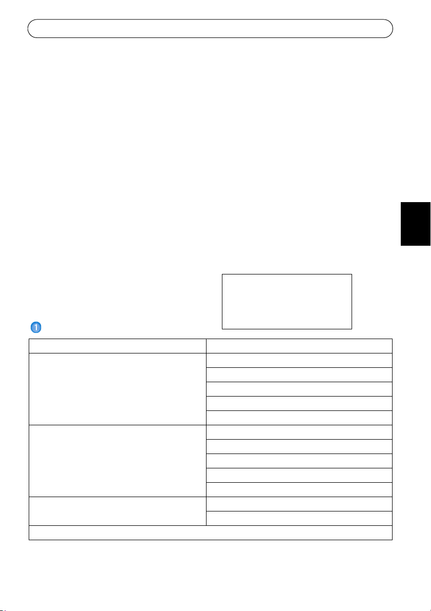
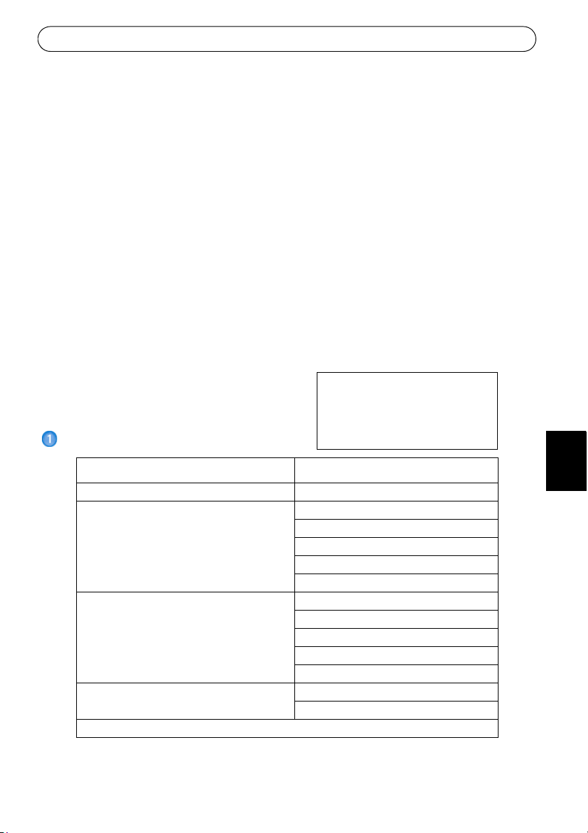
Package contents
Important!
This product must be installed in
compliance with local laws and
regulations.
ENGLISH
DEUTSCH
Fixed Dome Network Camera AXIS 225FD
Indoor Power Adapter
Note: The power adapter is country specific,
please check that the type of power adapter
you are using is correct
Mounting kit Tool for tamper-proof screws
Documentation AXIS 225FD Installation Guide
Warranty Document
Note: To comply with the vandal resistant design of the AXIS 225FD, it is necessary to use vandal
resistant conduits to protect the cables.
Europe
UK
Australia
USA/Japan
Korea
3 screws and plugs for solid walls
Cable gland with blind plugs
Drill template
Silica gel packet
Axis Network Video Product CD
ESPAÑOL
ITALIANO
Page 4
Page 4 AXIS 225FD Installation Guide
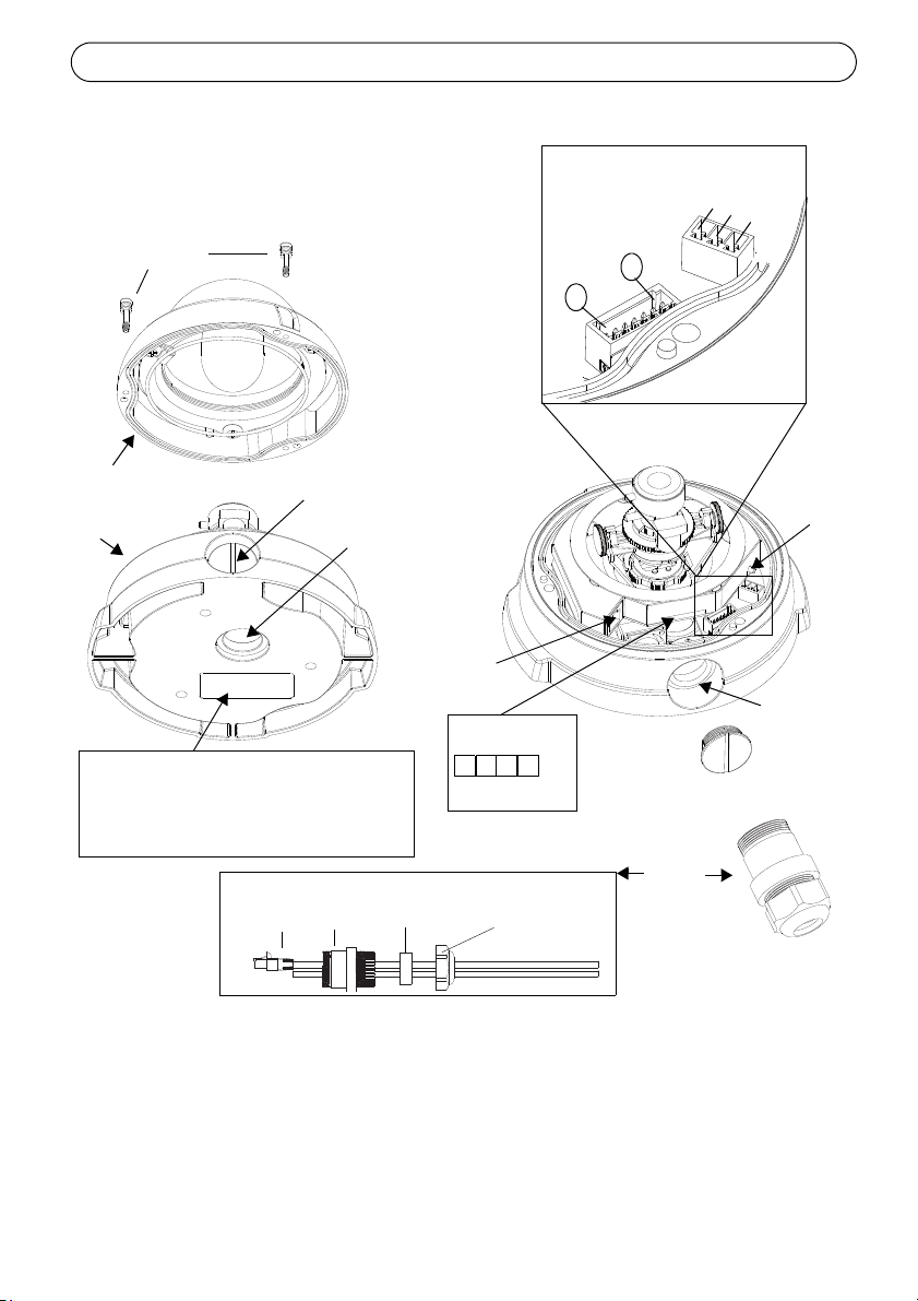
Conduit hole
Conduit hole
Network
connector
Serial number (S/N)
Control
Plug
LED
indicators
(see table 2)
1
2
3
4
The serial number is required
during the installation.
1
7
button
Power connector block
(see table 1)
I/O terminal
block
G
N
D
+
o
r
A
C
A
C
(side)
(bottom)
Tamper-proof
screws
Unit casing
Dome casing
Cable
Conduit
hole
Cables
Cable
gland
Outer
ring
gland
Rubber
plug
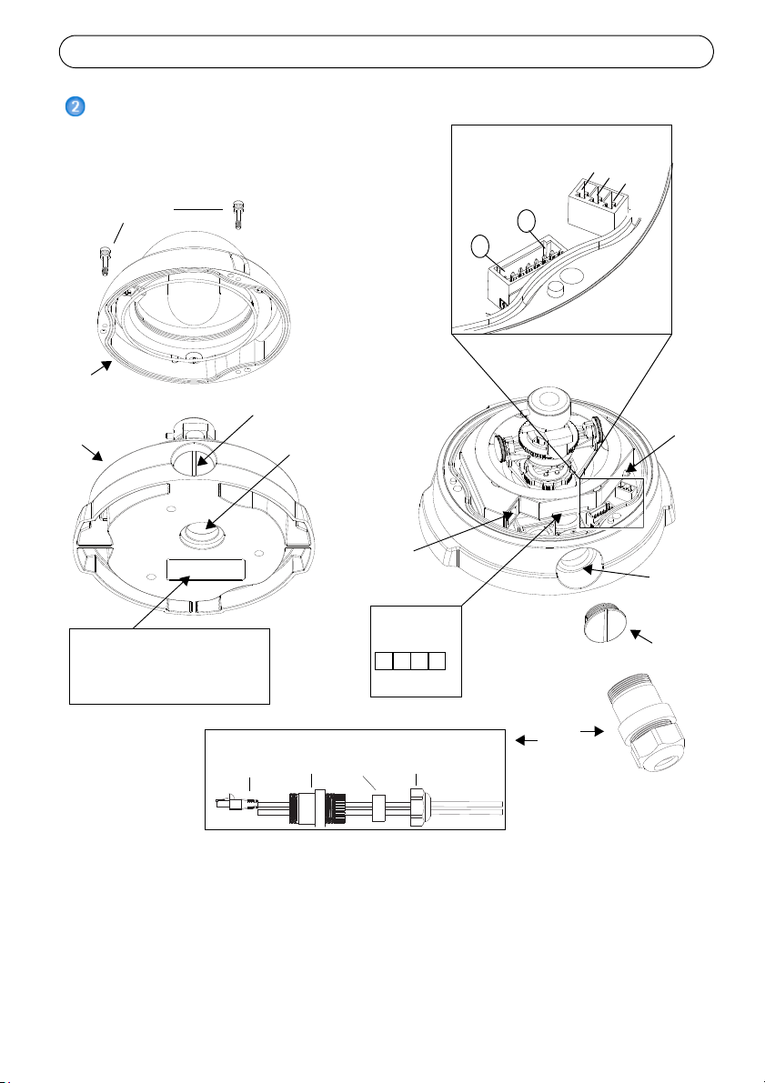
Hardware overview
Notes:
Important!
• Use cables and conduits that are suitable for the installation and that are in compliance
with the IP66 rated, outdoor-proof, vandal resistant design of the AXIS 225FD.
• Conduit dimensions: NPT 3/4" -14 (pipe thread).
If the AXIS 225FD is not mounted according to the instructions, there may be problems with
moisture which is not covered by warranty.
Page 5
AXIS 225FD Installation Guide Page 5
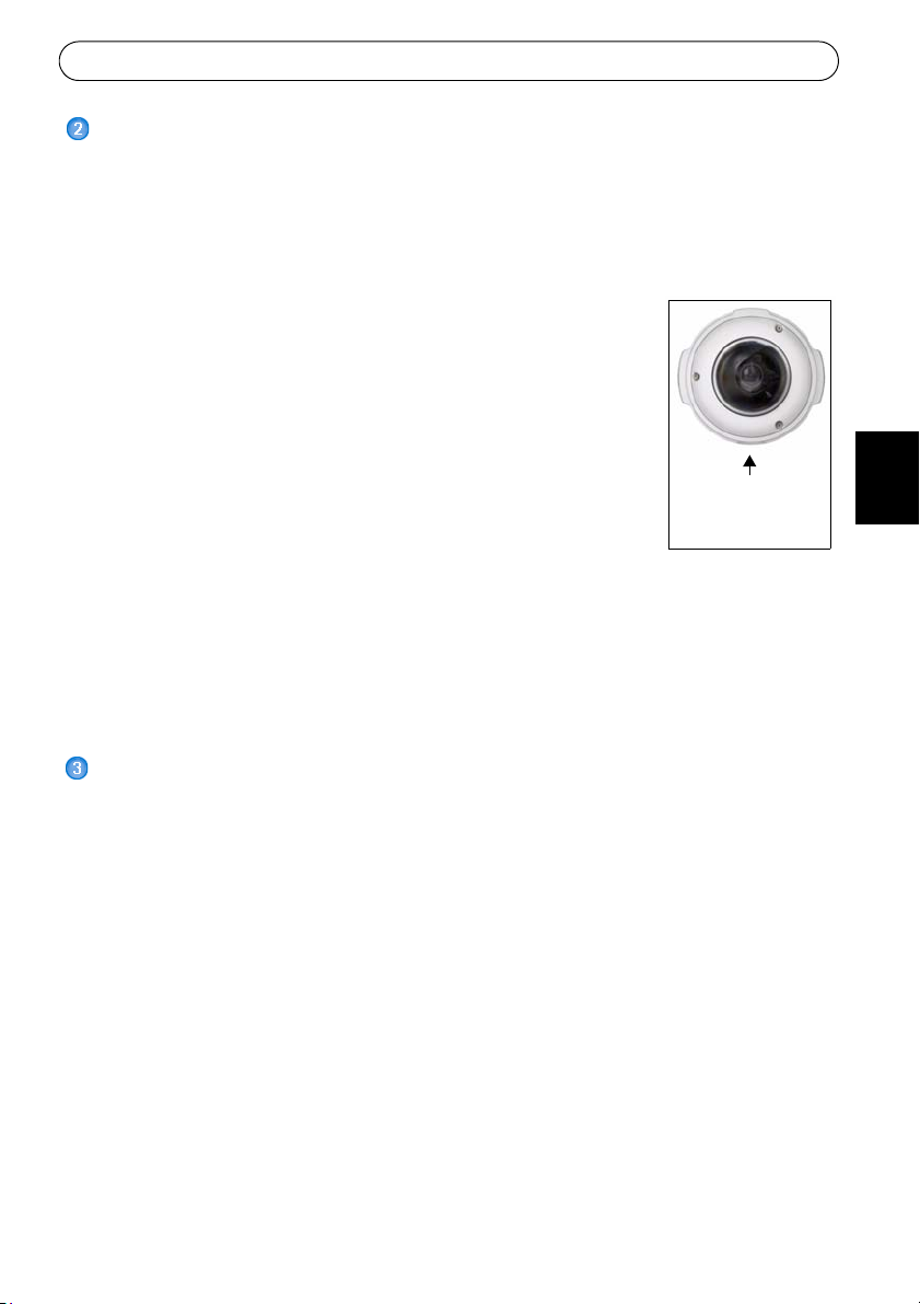
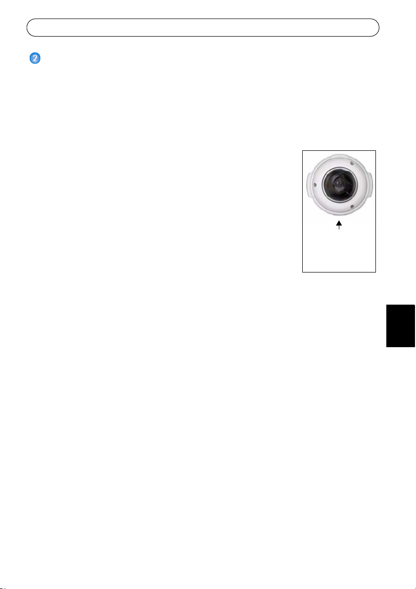
Conduit hole
must face
downwards
Install the hardware
Refer to the illustration on page 4 for a detailed overview of the AXIS 225FD.
1. Make a note of the serial number (S/N) which is located on the product label on the base
of the unit casing.
2. Loosen the tamper-proof screws using the supplied allen key and lift the dome casing
m the unit casing. Be careful not to damage the dome or scratch the glass.
fro
3. Disassemble the cable gland (see illustration).
4. Thread the network/power and I/O cables through the outer ring
rubber plug (push the network cable through the slit).
and
5. Use the supplied blind plugs to fill unused holes in the rubber plug.
6. Attach the cable gland to the condui
the AXIS 225FD, depending on the installation.
7. Route the cables through the cable gland, push the rubber plug into
ace and tighten the outer ring to secure the cables. Use silicon
pl
sealant, if necessary.
8. Using the drill template, drill th
The conduit hole must face downwards if the camera is installed
vertically.
9. Install the unit casing on the ceiling/wall u
holes with silicon sealant to prevent moisture from leaking in to the casing.
The serial number is used in the installation.
t hole on the side or bottom of
ree holes in the ceiling/wall.
sing the supplied screws and plugs. Seal the
ENGLISH
DEUTSCH
Note: Use of the cable gland is optional. For full vandal resistant protection of the cables, u
vandal resistant conduits instead.
Connect the cables
1. Connect the camera to the network using a shielded network cable.
2. Optionally connect external input/output devices, e.g. alarm devices. See page 14 for
information on the termi
3. Connect power to the power connector block,
• PoE (Power over Ethernet) via the network cable. This will automat
available via the network. Note that PoE provides power for the camera only (not the
heater).
• Connect the supplied indoor power adapter to t
casing. Note that this indoor power adapter provides power for the camera only (not the
heater).
• Connect an outdoor power supply to the power connector block in the camera casing. For
information on available outdoor power supplies, please visit the Support pages at http://
www.axis.com/techsup/
4. Check that the indicator LEDs indicate th
further details. Note that some LEDs can be disabled and may be unlit.
nal connector pins.
using one of the methods listed below:
ically be detected if
he power connector block in the camera
e correct conditions. See the table on page 14 for
se
ESPAÑOL
ITALIANO
Page 6
Page 6 AXIS 225FD Installation Guide
Assign an IP address
Most networks today have a DHCP server that automatically assigns IP addresses to connected
devices. If your network does not have a DHCP server the AXIS 225FD will use 192.168.0.90
as the default IP address.
If you would like to assign a static IP address th
AXIS IP Utility or AXIS Camera Management. Depending on the number of cameras you
wish to install, use the method that best suits your purpose.
Both of these free applications are available on the
with this product, or they can be downloaded from www.axis.com/techsup
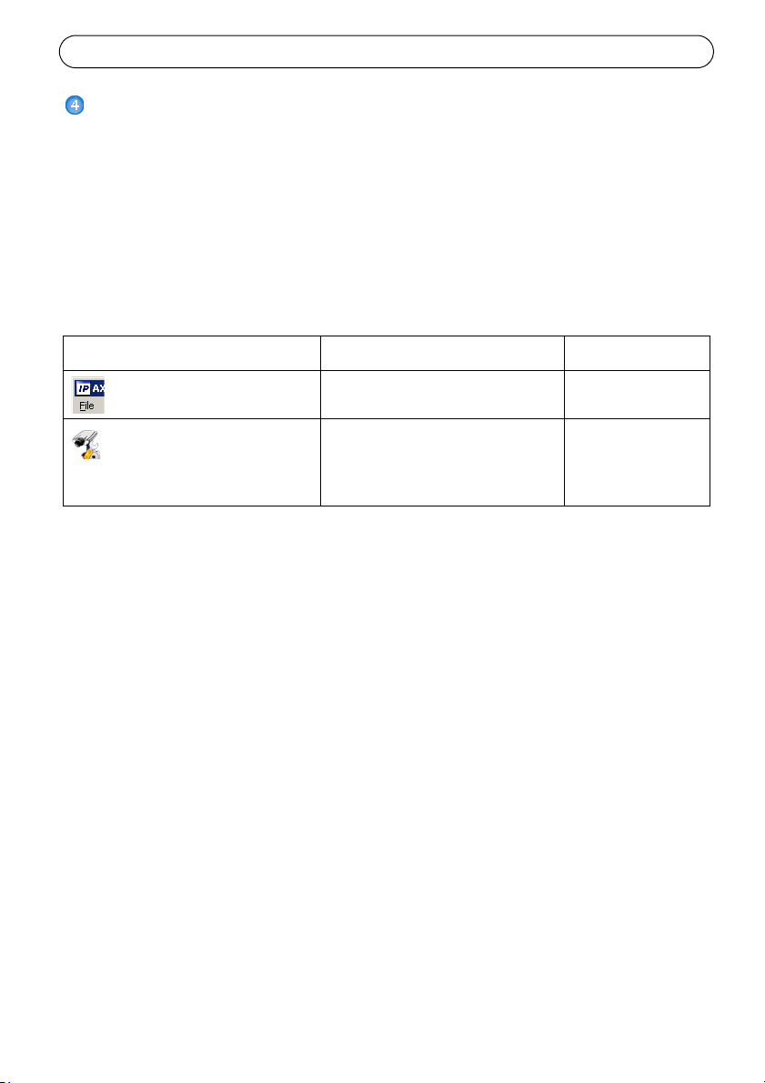
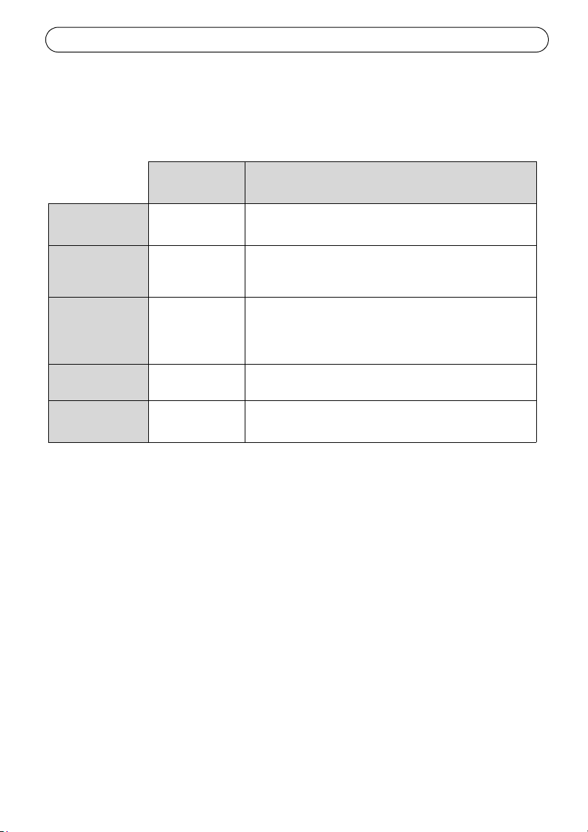
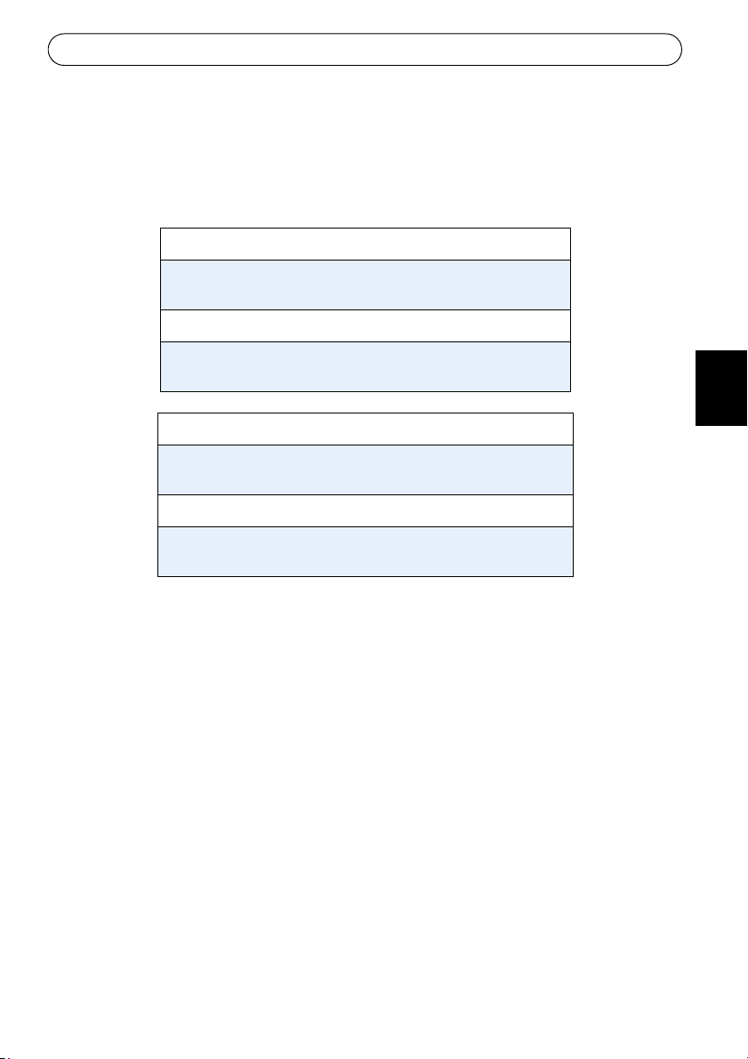
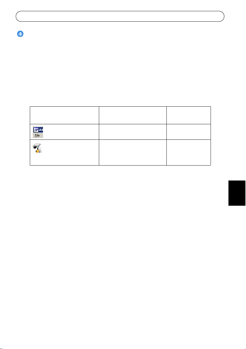
Method Recommended for Operating system
e recommended method in Windows is either
Axis Network Video Product CD supplied
AXIS IP Utility
See page 7
AXIS Camera Management
See page 15
Notes:
• If assigning the IP address fails, check that th
• For other methods of assigning or discovering the IP address of t
operating systems, see page 15.
Single camera
Small installations
Multiple cameras
Large installations
Installation on a different subnet
ere is no firewall blocking the operation.
Windows
Windows 2000
Windows XP Pro
Windows 2003
Server
he AXIS 225FD, e.g. in other
Page 7
AXIS 225FD Installation Guide Page 7
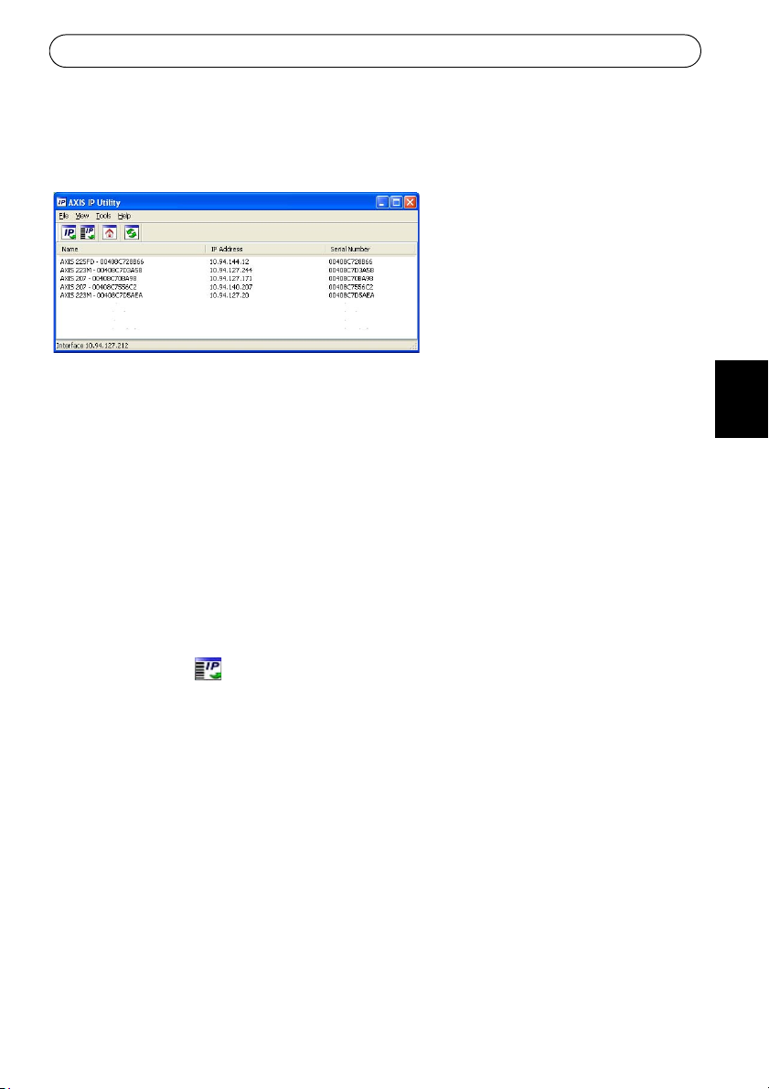
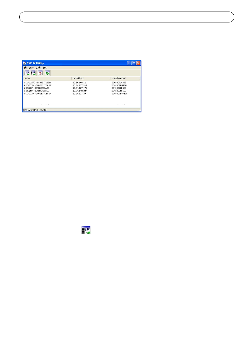
AXIS IP Utility - single camera/small installation
AXIS IP Utility automatically discovers and displays Axis devices on your network. The
application can also be used to manually assign a static IP address.
Note that the computer running AXIS IP Utility must be on the same network segment
(physical subnet) as the AXIS 225FD.
Automatic discovery
1. Check that the AXIS 225FD is connected to the network and that power has been applied.
2. Start AXIS IP Utility.
3. When the camera appears in the window, double-click it to open its home page.
4. See page 9 for instructions on how to assign the password.
Assign the IP address manually
1. Acquire an unused IP address on the same network segment as your computer.
2. Click the button Assign new IP address using serial number and enter the serial
number and IP address for the AXIS 225FD. The serial number is located on the product
lab
el.
3. Click the Assign bu
4. Click the Home P
See page 9 for instructions on how to set the password
tton and follow the instructions.
age button to access the camera’s web pages.
ENGLISH
DEUTSCH
ESPAÑOL
ITALIANO
Page 8
Page 8 AXIS 225FD Installation Guide
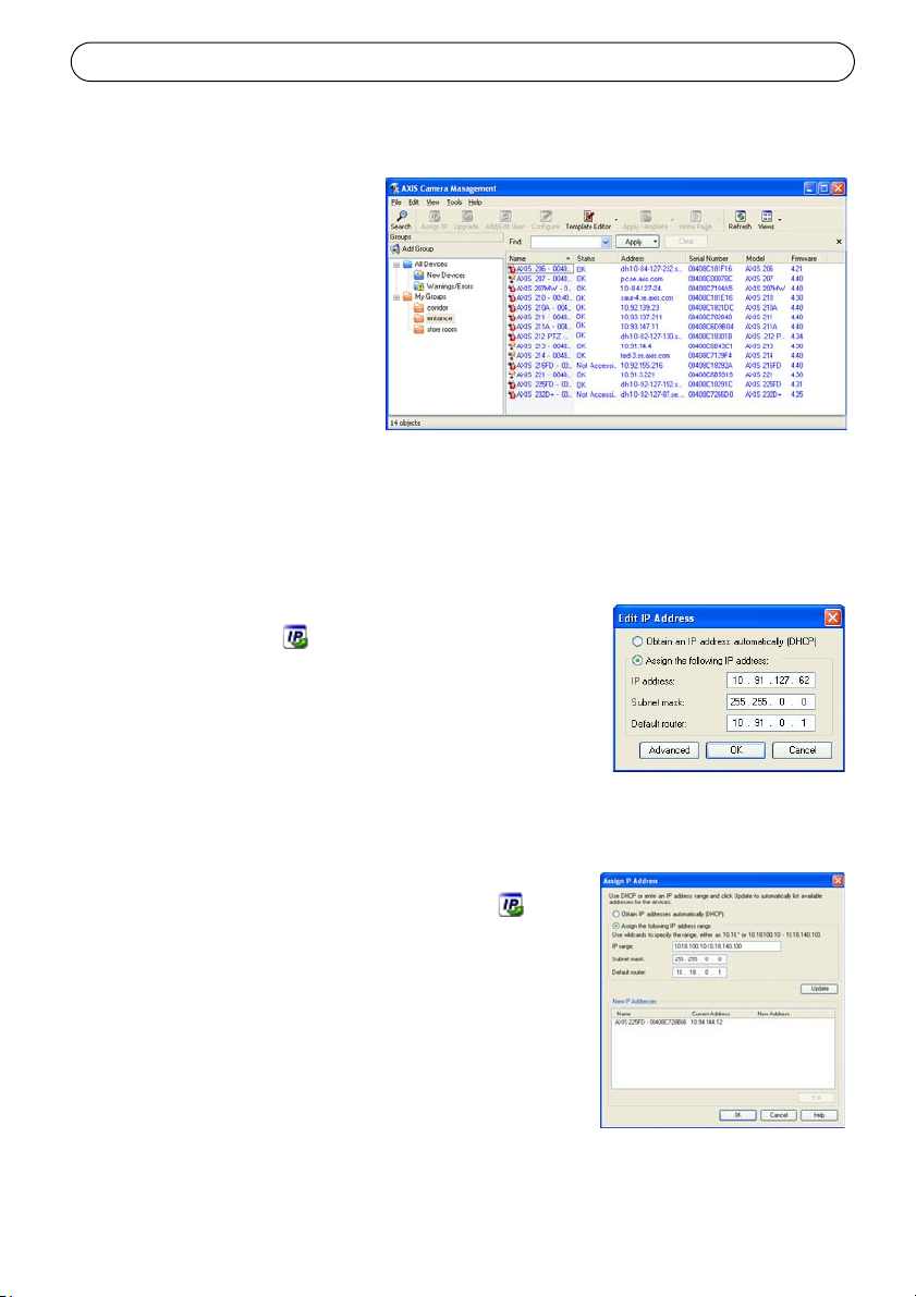
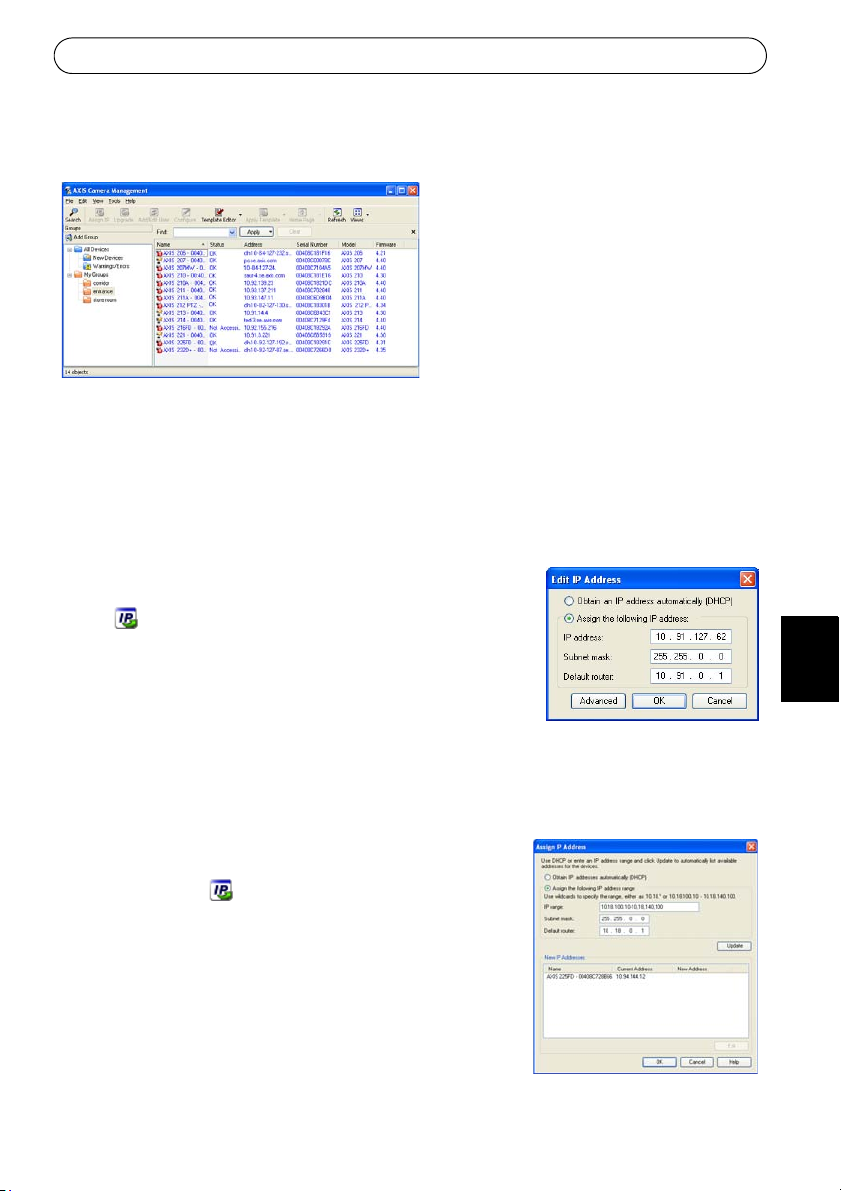
AXIS Camera Management - multiple cameras/large installations
AXIS Camera Management can
automatically discover multiple
Axis devices, show connection
status, manage firmware upgrades
and set IP addresses.
Automatic discovery
1. Check that the camera is connected to the network and that
has been applied.
power
2. Start AXIS Camera Management. When the AXIS 225F
click it to open the camera’s home page.
3. See page 9 for instructions on how to set the password.
D appears in the window, double-
Assign an IP address in a single device
1. Select AXIS 225FD in AXIS Camera Management and click
the Assign IP button.
2. Select Assign
address, subnet mask and default router the device will use.
3. Click the OK bu
the following IP address and enter the IP
tton.
Assign IP addresses in multiple devices
AXIS Camera Management speeds up the process of assigning IP addresses to multiple devices,
by suggesting IP addresses from a specified range.
1. Select the devices you wish to configure (different models
be selected) and click the Assign IP button.
can
2. Select A
range of IP addresses, the subnet mask and default router
the devices will use.
3. Click the OK bu
ssign the following IP address range and enter the
tton.
Page 9
AXIS 225FD Installation Guide Page 9
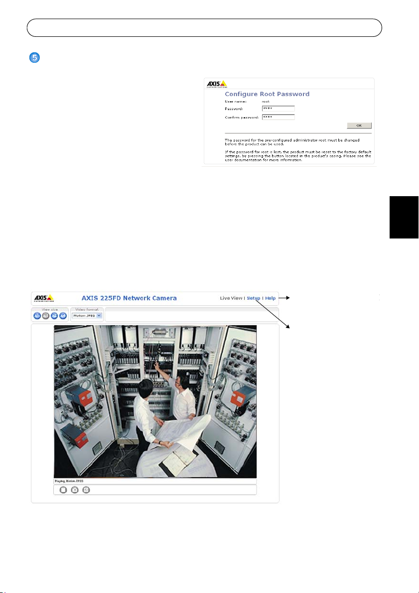
Setup - Provides all the
necessary tools for configuring the camera to suit
your requirements.
Help - Displays online help
on all aspects of using the
camera.
Setting the Password
When accessing the AXIS 225FD for the
first time, the ‘Co
dialog will be displayed on the screen.
4. Enter a password and then re-enter it,
to confir
5. Enter the User name: root
Note: T
name root is permanent and cannot be
deleted.
6. Enter the password as set in step 2 above, and click OK. I
225FD must be reset to the factory default settings. See page 15.
7. If required, click Ye
stream in your browser. You will need administrator rights on the computer to do this.
8. The Li
tools, which allow you to customize the camera to your specific needs.
9. Proceed to “Adjust the image” on page 10 to set the focus and zoom an
hardware installation.
nfigure Root Password’
m the spelling. Click OK.
he default administrator user
f the password is lost, the AXIS
s to install AMC (AXIS Media Control), to allow viewing of the video
ve View page of the AXIS 225FD is displayed, complete with links to the Setup
d complete the
ENGLISH
DEUTSCH
ESPAÑOL
ITALIANO
Page 10
Page 10 AXIS 225FD Installation Guide
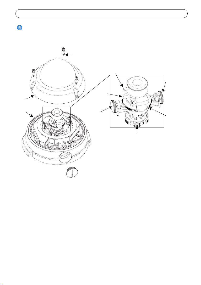
Pan adjustment ring
Image
Zoom
Focus puller
Tilt
screw
3 tamper-proof
screws
Unit casing
Dome casing
balance
ring
adjustment
Tilt
screw
adjustment
puller
Adjust the image
1. Open the Live View page in the Web interface and make the following adjustments:
2. Loosen the pan adjustment ring and tilt adjustme
pan adjustment ring, otherwise the lens may rotate with the lock ring and damage or
disconnect the cable.
3. Turn the lens to the desired direction. Do not turn the lens
cause the internal cables to disconnect.
4. Once satisfied, gently tighten the pan adjustment ring a
the camera’s position.
5. Turn the image balance ring to set the image to the correct angle.
6. Loosen the zoom puller counterclockwise, rotate the zoom ring and determine the desired
m position.
zoo
Note: Due to the dome’s refraction, the image might appear slightly out of focus once the dome has
been placed. To compensate, focus on an object slightly closer than the intended area.
nt screws. Hold the lens while turning the
more than 360° as this may
nd tilt adjustment screws to secure
Page 11
AXIS 225FD Installation Guide Page 11
Place silica gel
packet
here
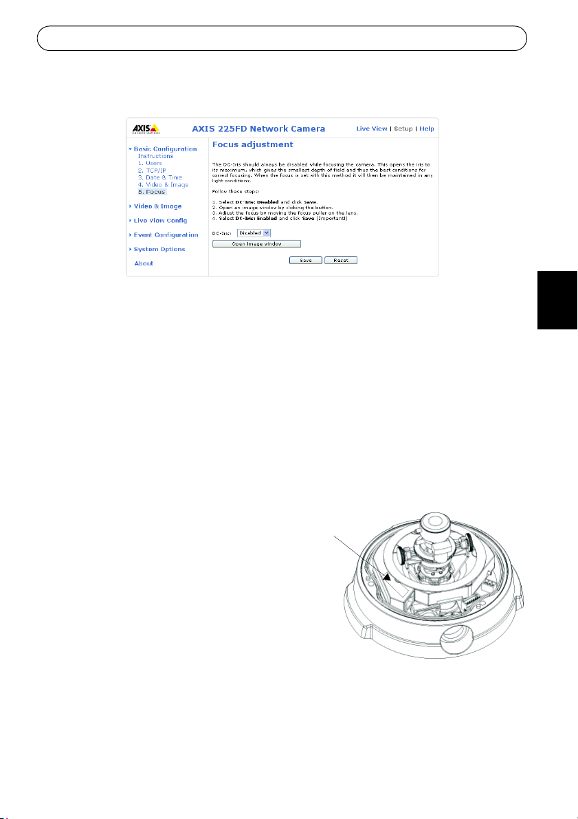
7. Go to the Basic Configuration menu in the Web interface and select Focus. Follow the
on-screen instructions to set the focus.
8. After determining the zoom and focus, lock the zoom puller and the focus puller in
ition by rotating the screws clockwise.
pos
ENGLISH
Note: The image can be fine-tuned for low lighting conditions.
Go to 'Setup > Video & Image > Advanced' and ref
er to the help files for more information.
Completing the installation
1. Check that the safety cord is attached to the hook to prevent the dome casing from falling
off the unit casing during the installation process. Be careful not to damage the dome or
scratch the glass.
2. Rotate the black protective shield inside the dome to match
3. Clean the dome with a dry soft cloth to remove dust and finger prints and use a blower to
remove dust from the lens.
4. Remove the silica gel packet from the
astic bag and remove the protective paper
pl
from the adhesive strip. Place the silica gel
packet on the camera unit as suggested in
the illustration.
5. Replace the dome casin
tamper-proof screws using the allen key.
The installation is now complete.
Note: The silica gel packet will absorb moisture
trapped in
sure to attach the packet so it does not obstruct
the camera, LED indicators or cable connections.
the dome casing during installation. Be
g and tighten the
the camera’s position.
DEUTSCH
ESPAÑOL
ITALIANO
Page 12
Page 12 AXIS 225FD Installation Guide
Other methods of setting the IP address
The table below shows the other methods available for setting or discovering the IP address.
All methods are enabled by default, and all can be disabled.
UPnP™
Bonjour
AXIS Dynamic
DNS Service
ARP/Ping
View DHCP server
admin pages
Operating
system
Windows
(ME or XP)
MAC OSX
(10.4 or later)
All A free service from Axis that allows you to quickly and
All See below. The command must be issued within 2 min-
All To view the admin pages for the network DHCP server, see
Notes
When enabled on your computer, the camera is automatically detected and added to “My Network Places.”
Applicable to browsers with support for Bonjour. Navigate
to the Bonjour bookmark in your browser (e.g. Safari) and
click on the link to access the camera’s web pages.
simply install your camera. Requires an Internet connection with no HTTP proxy. See www.axiscam.net for more
information.
utes of connecting power to the camera.
the server’s own documentation.
Page 13
AXIS 225FD Installation Guide Page 13
Setting the IP address with ARP/Ping
1. Acquire an IP address on the same network segment your computer is connected to.
2. Locate the serial number (S/N) on the AXIS 225FD product label.
3. Open a Command Prompt on your computer and enter the following commands
(as appropriate for your operating system):
Windows syntax:
arp -s <IP Address> <Serial Number>
ping -l 408 -t <IP Address>
Windows example:
arp -s 192.168.0.125 00-40-8c-18-10-00
ping -l 408 -t 192.168.0.125
UNIX/Linux/Mac syntax:
arp -s <IP Address> <Serial Number> temp
ping -s 408 <IP Address>
UNIX/Linux/Mac example:
arp -s 192.168.0.125 00:40:8c:18:10:00 temp
ping -s 408 192.168.0.125
4. Check that the network cable is connected to the
camera. Start/restart the camera by
disconnecting and reconnecting power.
5. Close the Command prompt
when you see ‘Reply from 192.168.0.125: ...’ or similar.
6. Start your browser, type in http://<IP address> in the Location/Address field and press
r on your keyboard.
Ente
7. See page 9 for instructions on how to set the password.
Notes:
• The ARP/Ping command must be issued within 2 minutes of connecting power to the
camera.
• To open a command prompt in Windows: from the Start
menu, select Run... and type
cmd (or command in Windows 98/ME). Click OK.
• To use the ARP command on a Mac OS X, use the Terminal utility, which is found under
Application > Utilities.
ENGLISH
DEUTSCH
ESPAÑOL
ITALIANO
Page 14
Page 14 AXIS 225FD Installation Guide
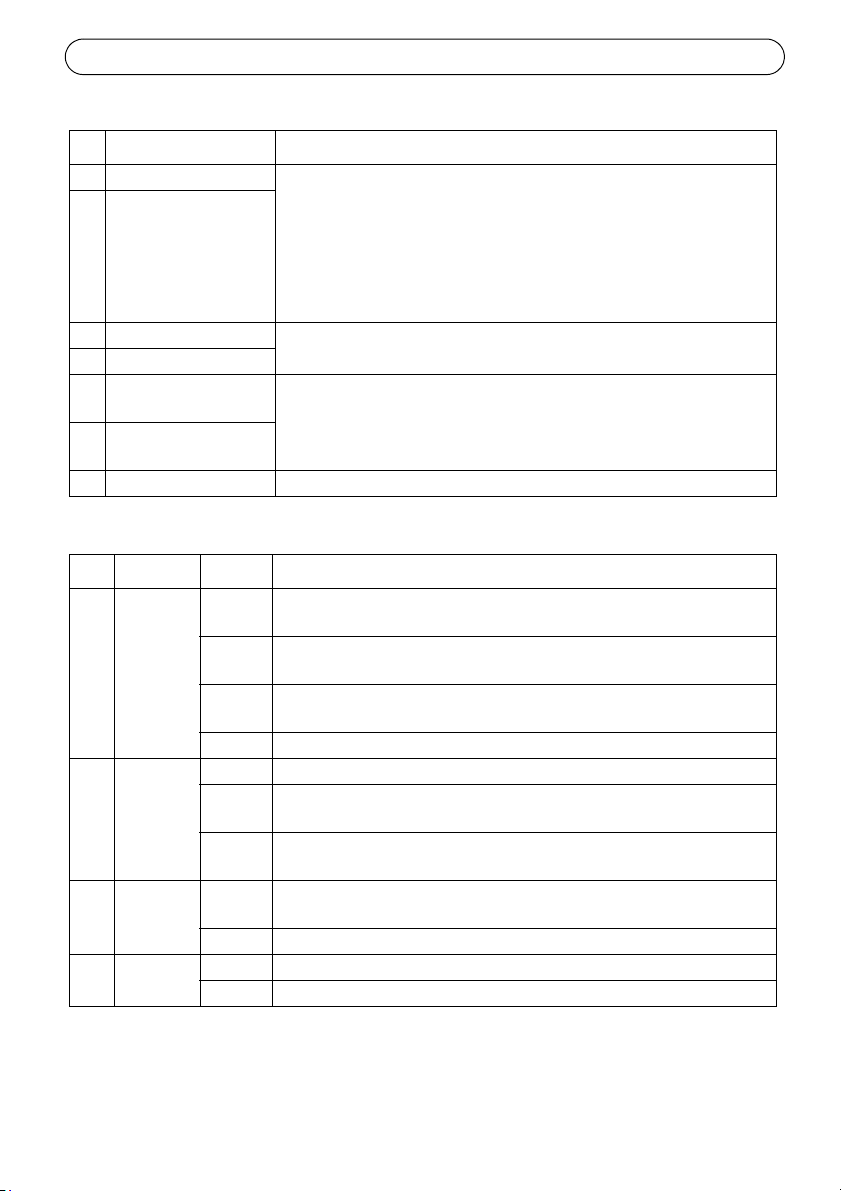
Table 1 - I/O terminal connector block
Pin Function Description
1 Output A On the external device output terminals (A and B), there is no distinc2 Output B
3 Digital Input 1 Connect to GND to activate, or leave floating (or unconnected) to
4 Digital Input 2
5 RS-485/422-A
(non-inverting)
6 RS-485/422-B
(inverting)
7 GND Ground.
tion between positive and negative (+ and -). The terminals use a photocoupler and are electrically isolated from the other internal
cuitry.
cir
The maximum load should not exceed 100mA and the maximum voltage should be not more than 50V DC. Note: Connecting AC to the output will damage the unit.
deactivate.
A half-duplex RS-485/422 interface for controlling auxiliary equip-
ment.
Table 2 - LED indicators
LED Function Color Description
1 Network Green Steady for connection to 100 Mbit/s network.
activity.
Amber Steady for connection to 10 Mbit/s network. Flashes for network activ-
ity.
Red Flashes rapid red, together with the Status indicator, for hardware
r.
erro
Unlit No connection.
2 Status Green Shows steady green for normal operation.
Amber Shows steady amber during reset to fact
settings.
Red Slow flash for failed upgrade. Rapid flash
indicator, for hardware error.
3 Heater Green Steady green when the power connected is sufficient for the heater
i.e. (12V DC min 20W or 24V AC min 25VA)
Red Insufficient power for the heater.
4 Power Green Normal operation.
Amber Flashes green/amber during firmware upgrade.
Flashes for network
ory default or when restoring
, together with the Network
Page 15

AXIS 225FD Installation Guide Page 15
Accessing the AXIS 225FD from the Internet
Once installed, your AXIS 225FD is accessible on your local network (LAN). To access the
camera from the Internet, network routers must be configured to allow incoming traffic,
which is usually done on a specific port. Please refer to the documentation for your router for
further instructions.
For more information on this and other topics, ple
www.axis.com/techsup
ase visit the Axis Support Web at
Resetting to the Factory Default Settings
This will reset all parameters, including the IP address, to the Factory Default settings:
1. Disconnect power from the camera.
2. Press and hold the Control button and reconnect power.
3. Keep the control button pressed until the Power Indicator flashes amber (this may take up
conds).
to 15 se
4. Release the control button.
5. When the Power Indicator displays green (which can tak
complete and the camera has been reset.
6. Re-install the AXIS 225FD using one of the
methods described in this document.
More information
Please refer to the help files and the user’s manual for information on the functionality of the
AXIS 225FD. The AXIS 225FD User’s Manual is available from the Axis Web site at http://
www.axis.com or from the Axis Network Video Product CD.
e up to 1 minute) the process is
ENGLISH
DEUTSCH
ESPAÑOL
ITALIANO
Page 16

Page 17
AXIS 225FD Guide d’installation Page 17
AXIS 225FD
Guide d’installation
Ce guide d’installation vous explique comment installer l’ AXIS 225FD Fixed Dome Network
Camera sur votre réseau. Pour d’autres informations sur l’utilisation de ce produit, consultez
le Manuel de l’utilisateur de l’ AXIS 225FD disponible sur le CD d’installation ou surfez sur
www.axis.com.
Étapes de l’installation
1. Vérifiez le contenu de la livraison à l’aide de la liste ci-dessous.
2. Installation du matériel - page 19
3. Branchement des câbles - page 20
4. Paramétrage de l’adresse IP - page 21
5. Définition du mot de passe - page 24
6. Réglage de l‘image - page 30.
Contenu de l’emballage
Important !
Ce produit doit être installé
conformément à la réglementation
en vigueur dans votre pays.
FRANCAIS
Article Titre/variantes
Fixed Dome Network Camera AXIS 225FD
Alimentation intérieure
Remarque : l’alimentation varie
Vérifiez que l’alimentation que vous utilisez est
adaptée.
Kit de montage Clé hexagonale pour vis inviolables
Documentation AXIS 225FDGuide d’installation
Document de garantie
selon le pays.
Europe
Royaume-Uni
Australie
États-Unis / Japon
Corée
3 vis et chevilles pour murs pleins
Presse-étoupe avec chevilles aveugles
Gabarit de perçage
Sachet de gel de silice
CD d’installation d’Axis
Page 18
Page 18 AXIS 225FD Guide d’installation
Trou de conduit
Trou de conduit
Connecteur
réseau
Bouton de
Trou de
Témoins
(voir tableau 2)
1
2
3
4
Notez le numéro de série et conservez-le
Le numéro de série (S/N) est nécessaire
pendant l’installation.
pour une utilisation ultérieure.
1
7
commande
Connecteurs
(voir tableau 1)
Terminaux
E/S
G
N
D
+
ou
C
A
C
A
(latéral)
(bas)
Vis inviolables
Boîtier
Boîtier du dôme
d’alimentation
DEL
conduit
Presse-
Câbles
Presseétoupe
Bague
extérieure
étoupe
Cheville en
caoutchouc
Description
Remarques :
• Utilisez des câbles, des presse-étoupe et des conduits adaptés à l’installation et à l’AXIS 225FD,
qui est conforme à l’indice de protection IP66, utilisable en extérieure et anti-effraction.
• Dimensions des conduits : NPT 3/4"
Important!
Si la caméra AXIS 225FD est montée de manière incorrecte, vous pouvez rencontrer des
problèmes d'humidité, non couverts par la garantie.
-14 (filetage du tuyau).
Page 19
AXIS 225FD Guide d’installation Page 19
Le trou du conduit
latéral doit être
tourné vers le bas
Installation du matériel
Reportez-vous à l’illustration à la page 18 pour une représentation détaillée de l’ AXIS
225FD.
1. Notez le numéro de série (S/N) de l’étiquette située au bas du boîtier. Le numéro de série
ra nécessaire pendant l’installation.
se
2. Desserrez les vis inviolables à l’aide de la clé hexagonale fournie et soulevez le boîtier du
ôme. Veillez à ne pas endommager le dôme ni à rayer la vitre.
d
3. Démontez le presse-étoupe (voir l’illustration).
4. Faites passer les câbles de réseau et d’alimentation ainsi que les
âbles d’E/S à travers la bague extérieure et la cheville en
c
caoutchouc (poussez le câble de rèseau à travers la fente).
5. Utilisez les chevilles aveugles fournies pour remplir les trous non
ilisés dans la cheville en caoutchouc.
ut
6. Fixez le presse-étoupe au trou de conduit situé sur le côté ou au
as de la caméra Axis 225FD, en fonction de l’installation.
b
7. Acheminez les câbles à travers le presse-étoupe, mettez en place la
heville en caoutchouc en la poussant et serrez la bague extérieure
c
pour fixer les câbles. Si nécessaire, utilisez du joint silicone pour
rendre le tout bien étanche.
8. Avec le gabarit de perçage, percez trois trous dans le plafond/mur. Le
latéral doit être tourné vers le bas si la caméra est installée à la verticale.
9. Fixez le boîtier au plafond/mur avec les vis et chevilles fournies. Refermez les trous avec
u joint silicone pour rendre le boîtier étanche.
d
Remarque:
L'utilisation du presse-étoupe
utilisez plutôt des conduits anti-effraction.
est facultative. Pour protéger les câbles contre toute effraction,
trou du conduit
FRANCAIS
Page 20
Page 20 AXIS 225FD Guide d’installation
Branchement des câbles
1.Branchez le câble réseau au connecteur de réseau de la caméra.
2. Branchez l’alimentation au connecteur d’alimentation, de l’une des manières suivantes :
• PoE (Power over Ethernet) via le câble réseau. Cett
détectée si elle est disponible via le réseau. La PoE alimente la caméra uniquement (par le
réchauffeur).
• Branchez l’alimentation intérieure fournie au connecteur d’alimentation dans le boîtier de la
caméra. De même, cette alimentation intérieure alimente la caméra uniquement (par le
réchauffeur).
• Branchez l’alimentation extérieure au connecteur d’alimentation dans le boîtier de la
caméra. Pour connaître la liste des alimentations extérieures disponibles, consultez les pages
de Support à l’adresse http://www.axis.com/techsup/
3. Vérifiez que les voyants du réseau, d’état et d’alimentation sont allumés et verts. Si vous
souhaitez utiliser le réchauffeur, vérifiez que son voyant est allumé et vert. Consultez le
tableau à la page 29 pour en savoir plus sur les voyants.
4. Reportez-vous à la section “Attribution d'une adresse IP” on page 21 pour savoir
comment assigner une adresse IP à l’ AXIS 225FD.
e connexion sera automatiquement
Page 21
AXIS 225FD Guide d’installation Page 21
Attribution d'une adresse IP
Aujourd'hui, la plupart des réseaux comportent un serveur DHCP qui attribue
automatiquement des adresses IP aux dispositifs connectés. Si ce n'est pas le cas de votre
réseau, l'AXIS 225FD utilisera l'adresse IP par défaut 192.168.0.90.
Si vous souhaitez affecter une adresse IP statiq
l'utilisation de l'application AXIS IP Utility ou de l'application AXIS Camera Management.
Selon le nombre de caméras à installer, utilisez la méthode qui vous convient le mieux.
Ces deux applications gratuites sont disponibles sur
fourni avec ce produit. Vous pouvez également les télécharger à partir du site www.axis.com/
techsup.
Méthode Recommandée pour Système
AXIS IP Utility
Voir page 22
AXIS Camera Management
Voir page 23
Une seule caméra
Les petites installations
Plusieurs caméras
Les grandes installations
Installation sur un autre sousréseau
Remarques :
• En cas d'échec de l'attribution de l'adresse IP, vérifiez qu'aucun pare-feu ne bloque
l'opération.
• Pour connaître les autres méthodes d'affectation
caméra AXIS 225FD, par exemple sur d'autres systèmes d'exploitation, reportez-vous à la
page 27.
ue, sous Windows nous recommandons
le CD de la caméra vidéo réseau Axis
d'exploitation
Windows
Windows 2000
Windows XP Pro
Windows 2003 Server
ou de repérage de l'adresse IP de la
FRANCAIS
Page 22
Page 22 AXIS 225FD Guide d’installation
AXIS IP Utility - Une seule caméra/petite installation
L'utilitaire AXIS IP Utility détecte et affiche automatiquement les périphériques Axis de votre
réseau. Cette application sert également à attribuer manuellement une adresse IP statique.
Notez que l'ordinateur exécutant l'appl
segment de réseau (sous-réseau physique) que l'appareil AXIS 225FD.
ication AXIS IP Utility doit se trouver sur le même
Détection automatique
1. Vérifiez que l'appareil AXIS 225FD est connecté au réseau et que l'alimentation est
activée.
2. Démarrez AXIS IP Utility.
3. Lorsque l'icône de la caméra apparaît dans la
la page d'accueil correspondante.
4. Consultez la page 30 pour savoir comment affecter le mot de passe.
fenêtre, double-cliquez dessus pour ouvrir
Affectez manuellement l'adresse IP.
1. Trouvez une adresse IP inutilisée sur le même segment de réseau que celui de votre ordinateur.
2. Cliquez sur le bouton Affecter l'adresse IP en utilisant le numéro de série, puis
saisissez le numéro de série et l'adresse IP de l'AXIS 225FD. Le numéro de série se trouve
sur l'étiquette du produit.
3. Cliquez sur le bouton Aff
4. Cliquez sur le bouton P
5. Consultez la page 30 pour savoir comment définir le mot de passe.
ecter et suivez les instructions.
age d’accueil pour accéder aux pages Web de la caméra.
Page 23
AXIS 225FD Guide d’installation Page 23
AXIS Camera Management - Plusieurs caméras/grandes installations
AXIS Camera Management peut détecter automatiquement plusieurs dispositifs Axis, afficher
les états de connexion, gérer les mises à niveau du microcode et définir les adresses IP.
Détection automatique
1. Vérifiez que la caméra est connectée au réseau et que l'alimentation est activée.
2. Démarrez AXIS Camera Management. Doubl
lorsqu'elle apparaît dans la fenêtre de façon à ouvrir la page d'accueil.
3. Consultez la page 30 pour savoir comment définir le mot de passe.
Attribuer une adresse IP à un seul dispositif
1. Sélectionnez AXIS 225FD dans l'application AXIS Camera Management, puis cliquez sur le bouton Affecter une
IP
2. Sélectionnez Affecte
l'adresse IP, le masque de sous-réseau et le routeur par
défaut que le dispositif utilisera.
3. Cliquez sur le bouton OK.
r l’adresse IP suivante et saisissez
e-cliquez sur l'icône de l'AXIS 225FD
FRANCAIS
Attribuer des adresses IP à plusieurs dispositifs
AXIS Camera Management accélère le processus d'affectation d'adresses IP sur plusieurs
appareils en suggérant les adresses IP parmi une plage spécifiée.
1. Sélectionnez les appareils à configurer (il peut s'agir de
lusieurs modèles), puis cliquez sur le bouton Affecter
p
une adresse IP.
2. Sélectionnez Affecter la plage d’adresses IP suivante et l
saisissez la plage d'adresses IP, le masque de sous-réseau
et le routeur par défaut que les dispositifs utiliseront.
3. Cliquez sur le bouton OK.
Page 24

Page 24 AXIS 225FD Guide d’installation
Setup - contient tous les
outils nécessaires pour
adapter la caméra à vos
besoins.
Help - affiche une aide en
ligne sur tous les modes
d’utilisation de la caméra.
Définition du mot de passe
Si vous accédez à la caméra AXIS 225FD
pour la première fois, la boîte de dialogue «
Configur
l’écran.
1. Entrez un mot de passe et entrez-le une
2. Entrez le nom d’utilisateur : root
3. Entrez le mot de passe comme expliqué à l’étape 2 et cliquez sur OK. Si
4. Si nécessaire, cliquez sur Oui pou
5. La page Li
6. Consultez la section “Accès à la caméra AXIS 225FD depuis Internet” on page 30 pour
e Root Password » s’affiche sur
nde fois pour en confirmer
seco
l’orthographe. Cliquez sur OK.
Remarque : Le
nom d’utilisateur par
défaut de l’administrateur, à savoir root, est permanent et ne peut pas être supprimé.
vous avez oublié
votre mot de passe, vous devrez rétablir les paramètres d’usine de la caméra AXIS 225FD.
Reportez-vous à la page 30.
r installer AMC (Axis Media Control) afin de pouvoir
voir le flot vidéo dans votre navigateur. Pour ce faire, vous devrez être connecté à votre
ordinateur avec les droits d’administrateur.
ve View de la caméra AXIS 225FD s’affiche, avec des liens vers les outils de
configuration qui vous permettent d’adapter la caméra à vos propres besoins.
régler la mise au point et le zoom et te
rminer l’installation du matériel.
Page 25

AXIS 225FD Guide d’installation Page 25
Bague de réglage du panoramique
Bague
Zoom
Mise au point
Vis de
l’inclinaison
3 vis
inviolables
Boîtier
Boîtier du dôme
de réglage
réglage de
Vis
de
de réglage
l’inclinaison
de la
balance de
l’image
Réglage de l‘image
FRANCAIS
1. Ouvrez la page Live View dans l’interface Internet et effectuez les réglages suivants :
2. Dévissez la bague de réglage du panoramique et les vis de réglage de l’inclinaison. Tenez
’objectif tout en tournant la bague du panoramique. À défaut, l’objectif pourrait tourner
l
avec la bague de blocage et endommager et déconnecter le câble.
3. Tournez l’objectif dans le sens souhaité. Ne pas tou
pas débrancher les câbles internes.
4. Une fois que vous avez terminé, serrez délicatement la
réglage de l’inclinaison pour bien fixer la caméra.
5. Tournez la vis de réglage de la balance pour définir un angle adéquat.
6. Desserrez le zoom dans le sens contraire des aigu
zoom et choisissez la position du zoom.
Remarque: Dû à la réfraction du dôme, l’image peut appar
que le dôme est placé, Pour compenser, il faut mettre le foyer légèrement proche de la
zone préfèrée.
rner l’objectif à plus de 360° pour ne
barre du panoramique et les vis de
illes d’une montre, tournez la bague du
aître lègèrement hors du foyer une fois
Page 26

Page 26 AXIS 225FD Guide d’installation
Placer le sachet de
gel de silice ici
7. Dans le menu Basic
Configuration
(configuration de base)
de l’interface Internet,
sélectionnez Focus (mise
au point). Suivez les
instructions affichées
sur l’écran pour la mise
au point.
8. Une fois le zoom et la
mise au
verrouillez le zoom et la
mise au point en tournant les vis adéquats dans le sens des aiguilles d’une montre.
Remarque: L’image peut être ajustée en cas de faible éclairage. Accédez à « Setup > Video & Image >
Terminer l’installation
1. Vérifiez que le cordon de sécurité est attaché au crochet pour empêcher le dôme de
tomber du boîtier pendant l’installation. Veillez à ne pas endommager le dôme ni à rayer
la vitre.
2. Tournez l’écran protecteur noir à l’intérieur
caméra.
3. Nettoyez le dôme avec un chiffon doux et sec pou
doigt. Dépoussiérez l’objectif avec un ventilateur.
4. Retirer le sachet de gel de silice (ou
sili
papier de protection des bandes
adhésives. Placer le sachet de gel de
silice sur la caméra - voir illustration.
5. Remettez le boîtier du dôme en place
et serre
hexagonale. L’installation est
terminée.
Remarque: Le sachet de gel de silice absorbera
point réglés,
Advanced » et consultez les fichiers d’aide pour en savoir plus.
du dôme conformément à la position de la
r enlever la poussière et les traces de
ca gel) du sac plastique et enlever le
z les vis inviolables avec la clé
a condensation piégée dans le
l
dome durant l'installation du produit. Faire attention de bien attacher le sachet pour qu'il
ne gêne pas la camera, les connecteurs ou les voyants.
Page 27

AXIS 225FD Guide d’installation Page 27
Autres méthodes de définition de l'adresse IP
Le tableau ci-dessous indique les autres méthodes permettant de définir ou de déterminer
l'adresse IP. Toutes les méthodes sont activées par défaut et désactivables.
UPnP™
Bonjour
AXIS Internet
Dynamic DNS
Service
ARP/Ping
Serveur DHCP
Système
Remarques
d'exploitation
Windows
(ME ou XP)
MAC OSX
(10.4 ou version ultérieure)
Tous Service Axis gratuit vous permettant d'installer rapidement votre caméra
Tous Reportez-vous aux instructions ci-dessous. La commande doit être saisie
Tous Pour consulter les pages administratives du serveur DHCP réseau, reportez-
Lorsque la caméra est activée sur votre ordinateur, elle est détectée et
ajoutée automatiquement au dossier Favoris réseau.
Applicable aux navigateurs prenant en charge Bonjour. Accédez au raccourci de Bonjour dans votre navigateur (par exemple, Safari), puis cliquez
sur le lien pour accéder aux pages Web de la caméra.
en toute simplicité. Nécessite une connexion Internet sans proxy HTTP Pour
plus d'informations, visitez le site www.axiscam.net.
dans les 2 minutes suivant la connexion de l'alimentation à la caméra.
vous à la documentation du serveur.
FRANCAIS
Page 28

Page 28 AXIS 225FD Guide d’installation
Définition de l'adresse IP à l'aide d'ARP/Ping
1. Trouvez une adresse IP sur le même segment de réseau que celui de votre ordinateur.
2. Repérez le numéro de série (S/N) sur l'étiquette de la caméra AXIS 225FD.
3. Ouvrez une invite de commande sur votre ordinateur et entrez les commandes suivantes :
Syntaxe pour Windows
arp -s <adresse IP> <numéro de série>
ping -l 408 -t <adresse IP>
Exemple pour Windows
arp -s 192.168.0.125 00-40-8c-18-10-00
ping -l 408 -t 192.168.0.125
Syntaxe pour UNIX/Linux/Mac
arp -s <adresse IP > <numéro de série> temp
ping -s 408 <adresse IP>
Exemple pour UNIX/Linux/Mac
arp -s 192.168.0.125 00:40:8c:18:10:00 temp
ping -s 408 192.168.0.125
4. Vérifiez que le câble réseau est connecté à la caméra, puis démarrez/redémarrez cette
dernière en débranchant, puis en rebranchant l'alimentation.
5. Fermez la commande d'invite q
uand vous voyez « Reply from 192.168.0.125: ...’ (Réponse
de 192.168.0.125 : ...) ou un message similaire.
6. Dans votre navigateur, tapez http://<adresse
IP> dans le champ Emplacement/Adresse,
puis appuyez sur Entrée sur le clavier.
Remarques :
• Pour ouvrir une invite de commande sous Windows : dans le menu Démarrer, sélectionnez Exécuter...
et tapez cmd. Cliquez sur OK.
• Pour utiliser la commande ARP sur Mac OS X, utilisez l'utilitaire Terminal dans Application > Utilitaires.
Page 29

AXIS 225FD Guide d’installation Page 29
Tableau 1 – Connecteurs pour terminaux E/S :
Bro
Fonction Description
che
1 Sortie A Sur les terminaux de sortie externes (A et B), il n’y a aucune distinction entre le
2 Sortie B
3 Entrée numérique 1 Connectez au GND pour l’activer ou laissez flot
4 Entrée numérique 2
5 RS-485/422-A
(non inverseuse)
6 RS-485/422-B
(inverseuse)
7 GND Terre.
positif et le négatif (+ et -). Les terminaux utilisent un photocoupleur
isolés électriquement de l’autre circuit interne.
La charge maximale autorisée est de 100
pas dépasser 50V DC. Remarque : si vous branchez l’alimentation CA à la sortie,
l’appareil sera endommagé.
désactiver.
Une interface RS-485/422 bidirectionnelle non
matériel auxiliaire.
mA et la tension maximale ne doit
ter (ou déconnectée) pour la
simultanée pour commander le
et sont
Tableau 2 - Témoins DEL :
DEL Fonction Couleur Description
1 Connecteur Vert Continu en cas de connexion à un réseau 100 Mbits/s. Clignote en cas d’activité
réseau.
Orange Continu en cas de connexion à un réseau 10 Mbits/s. Clignote en cas d’activité
Rouge Clignote rapidement en rouge, avec le
Éteint Pas de connexion.
2 État Vert Vert continu en cas de fonctionnement normal.
Orange Orange en continu pendant la réinitialis
Rouge Clignote lentement en cas d’échec de la m
3 Réchauffeur Vert Vert en continu lorsque le réchauffeur
Rouge Alimentation insuffisante du
4 Alimenta-
tion
Vert Fonctionnement normal.
Orange Clignote en vert/orange pendant la mi
réseau.
voyant d’état, pour signaler une panne
du matériel.
ation des valeurs d’usine ou des
paramètres.
ise à niveau. Clignote rapidement,
avec le témoin du réseau, pour signaler une panne du matériel.
est suffisamment alimenté
(12V DC min. 20W ou 24V CA min. 25VA)
réchauffeur.
se à niveau du microprogramme.
FRANCAIS
Page 30

Page 30 AXIS 225FD Guide d’installation
Accès à la caméra AXIS 225FD depuis Internet
Une fois installée, votre caméra AXIS 225FD est accessible depuis votre réseau local (LAN).
Pour accéder à la caméra depuis Internet, vous devez configurer les routeurs réseau afin
d’autoriser l’entrée de données, ce qui se fait généralement sur un port spécifique. Consultez la
documentation de votre routeur pour obtenir davantage d’instructions.
Pour de plus amples informations, visitez le site
de support d’Axis sur www.axis.com/techsup.
Rétablissement des paramètres par défaut définis en usine
Procédez comme suit pour revenir aux paramètres par défaut définis en usine et réinitialiser
l’adresse IP :
1. Débranchez l’alimentation de la caméra.
2. Maintenez enfoncé le bouton de commande et rebranchez l’alimentation.
3. Appuyez sur le bouton jusqu’à ce que le voyant d’alimentati
clignote (cela peut prendre jusqu’à 15 secondes).
4. Relâchez le bouton.
5. Quand le voyant d’alimentation émet une l
minute), la caméra est revenue aux réglages par défaut définis en usine.
6. Réinstallez la caméra AXIS 225FD à l’aide d’une
ce document.
umière verte (ce qui peut prendre jusqu’à 1
des méthodes d’installation décrites dans
on passe à l’orange et
Informations complémentaires
Consultez les fichiers d’aide et le manuel de l’utilisateur pour en savoir plus sur les fonctions
de l’ AXIS 225FD. Le Manuel d'utilisation de l’ AXIS 225FD est disponible sur le site Web
d'Axis à l'adresse http://www.axis.com et sur le CD d’installation d’Axis.
Page 31

AXIS 225FD Montageanweisung Seite 31
AXIS 225FD
Montageanweisung
In dieser Anleitung wird die Installation der Kamera AXIS 225FD Fixed Dome Network
Camera im Netzwerk beschrieben. Alle anderen Aspekte der Nutzung dieses Produkts werden
im AXIS 225FD Benutzerhandbuch beschrieben, das sich auf der mitgelieferten Axis
Installations-CD befindet. Sie können das Benutzerhandbuch auch von unserer Website
www.axis.com herunterladen.
Installationsschritte
1. Prüfen Sie, ob alle in der weiter unten folgenden Liste aufgeführten Komponenten vorhanden sind.
2. Installieren Sie die Hardware – Seite 33.
3. Schließen Sie die Kamera an – Seite 34.
4. Legen Sie die IP-Adresse fest – Seite 35.
5. Legen Sie das Kennwort fest – Seite 38.
6. Stellen Sie das Bild ein – Seite 39.
Wichtig!
Die Installation dieses Produkts
muss in Übereinstimmung mit den
geltenden Gesetzen und
Bestimmungen erfolgen
DEUTSCH
Lieferumfang
Komponente Bezeichnung/Variante
Fixed Dome Network Camera AXIS 225FD
Netzteil für geschlossene Räume
Hinweis: Das Netzteil ist landesspezifisch. Stellen
Sie sicher, das
Montagesatz inbus-Schlüssel für zugriffssichere Schrauben
Dokumentation AXIS 225FD Installationsanleitung
Garantieerklärung
s Sie das richtige Netzteil verwenden.
Europa
Großbritannien
Australien
USA/Japan
Korea
3 Schrauben und Dübel für feste Wände
Kabeldurchführung mit Blindstecker
Bohrschablone
Silikagelpäckchen
Axis Installations-CD
Page 32

Seite 32 AXIS 225FD Montageanweisung
Kabelöffnung
Kabelöffnung
Netzwerkanschluss
Seriennummer (S/N)
Steuer-
Kabelöffnung
Stopfen
LEDanzeigen
(siehe Tabelle 2)
1
2
3
4
Die Seriennummer wird
für die Installation benötigt.
1
7
taste
Stromanschlussleiste
(siehe Tabelle 1)
E/A-Anschlussleiste
M
a
ss
e
+
o
de
r
AC
A
C
(Seite)
(Unterseite)
zugriffssichere
Schrauben
Kameragehäuse
Kuppelhaube
Kabel
Kabeldurchführung
Ausenring
Verschlussstopfen
Kabeldurchführung
Beschreibung
Hinweise:
• Verwenden Sie Kabel, Schutzrohrmuffen und Kabelführungen, die für die Installation geeignet
sind und zu dem vandalismussicheren, wetterfesten Gehäuse der AXIS 225FD mit Schutzklasse
IP66 passen.
• Leitungsabmessungen: NPT 3/4" -14 (Rohrgewinde).
WICHTIGER HEINWEIS!
• Wenn die AXIS 225FD nicht entsprechend dieser Installationsanleitung montiert wird, können
Probleme mit Feuchtigkeit auftreten, welche nicht durch die Garantie abgedeckt werden.
Page 33

AXIS 225FD Montageanweisung Seite 33
Kabelöffnung
muss nach
unten zeigen!
Installieren der Hardware
In der Abbildung auf Seite 32 finden Sie einen detaillierten Überblick über die
Netzwerkkamera AXIS 225FD.
1. Notieren Sie sich die Seriennummer (S/N) der Kamera. Diese befindet sich auf dem Produktaufkleber an der Unterseite des Gehäuses. Di
benötigt.
2. Lösen Sie mit Hilfe des Inbus-S
Kuppelhaube vom Gerätegehäuse ab. Achten Sie darauf, dass die Kuppelhaube nicht
beschädigt und das Glas nicht zerkratzt wird.
3. Entfernen Sie die Kabeldurchfüh
4. Führen Sie die Netzwerk-, Strom- und E/A Kabel durch den
ßenring und den Verschlussstopfen (Drücken Sie das
Au
Netzwerkkabel durch den seitlichen Schlitz).
5. Verwenden Sie die mitgelieferten Bli
Öffnungen im Verschlussstopfen zu schließen.
6. Verschrauben Sie die Kabeldurchführung mit der Kabelöffnung auf
r Seite oder Unterseite der AXIS 225FD, abhängig von den
de
Installation.
7. Führen Sie die Kabel durch die Kabeldurchführung, drücken Sie den
erschlussstopfen in die Öffnung und befestigen Sie den Außenring
V
um die Kabel zu fixieren. Verwenden Sie Silikon zum Abdichten wenn nötig.
8. Bohren Sie mit Hilfe der Bohrschablone drei Löcher in die Decke bzw. Wand. Wi
Kamera an der Wand angebracht, muss die Kabelöffnung an der Seite des Gehäuses
nach unten zeigen.
9. Schrauben Sie das Gehäuse an die Decke bzw. Wand. Verwenden Sie dazu die
lieferten Schrauben und Dübel. Dichten Sie die Löcher mit Silikondichtungsmasse
mitge
ab, damit keine Feuchtigkeit in das Gehäuse eindringen kann.
chlüssels die zugriffssicheren Schrauben, und heben Sie die
rung (siehe Zeichnung.)
ndstecker um nicht verwendete
e Seriennummer wird für die Installation
rd die
DEUTSCH
Hinweis: Der Gebrauch der Kabeldurchführung ist optional. Für
Kabel sollten vandalisierungssichere Kabeldurchführungen benutzt werden.
vollen vandalsicheren Schutz der
Page 34

Seite 34 AXIS 225FD Montageanweisung
Anschließen der Kabel
1. Schließen Sie das Netzwerkkabel an den Netzwerkanschluss der Kamera an.
2. Schließen Sie das Stromkabel an die Stromanschlussleiste an. Sie haben folgende
ichkeiten:
Mögl
• PoE (Power over Ethernet) über das Netzwerkkab
diese Option von Ihrem Netzwerk unterstützt wird. Beachten Sie, dass PoE nur den Strom
für die Kamera (nicht für das Heizelement) bereitstellt.
• Schließen Sie das mitgelieferte Netzteil an di
Beachten Sie, dass dieses Netzteil nur den Strom für die Kamera (nicht für das
Heizelement) bereitstellt.
• Schließen Sie ein Netzteil für Außenmontage an die Stromanschlussleiste im
Kamerag
finden Sie auf unserer Website auf den Supportseiten unter http://www.axis.com/techsup/.
3. Überprüfen Sie, ob die Netzwerk-, Status- und Netz
Sie Sie das Heizelement verwenden, prüfen Sie zusätzlich dessen entsprechende Anzeige.
Ein Beschreibung der LED-Anzeigen finden Sie in der Tabelle 2 auf Seite 43.
4. Im Abschnitt “IP-Adresse zuweisen”auf Seite 35 wird beschrieben, wie Sie der Kamera
AXIS 225FD eine IP-Adresse zuweisen.
ehäuse an. Nähere Informationen zu verfügbaren Netzteilen für Außenmontage
el. Die Kamera erkennt automatisch, ob
e Stromanschlussleiste im Kameragehäuse an.
anzeige (LED) grün aufleuchten. Wenn
Page 35

AXIS 225FD Montageanweisung Seite 35
IP-Adresse zuweisen
In den meisten Netzwerken ist heutzutage ein DHCP-Server eingebunden, der
angeschlossenen Geräten automatisch IP-Adressen zuweist. Wenn Ihr Netzwerk über keinen
DHCP-Server verfügt, wird für die AXIS 225FD die Standard-IP-Adresse 192.168.0.90
verwendet.
Zum Zuweisen einer statischen IP-Adresse
Utility und AXIS Camera Management zur Verfügung. Verwenden Sie die Methode, die für
die gewünschte Anzahl der zu installierenden Kameras geeignet ist.
Beide Anwendungen stehen kostenlos auf der mitgelieferten CD für Axis-
tzwerkvideoprodukte zur Verfügung oder können unter www.axis.com/techsup
Ne
heruntergeladen werden.
Methode Empfohlen für Betriebssystem
AXIS IP Utility
Siehe Seite 36
AXIS Camera Management
Siehe Seite 37
Hinweise:
• Falls Sie die IP-Adresse nicht zuweisen können, müssen ggf
Firewall überprüft werden.
• Weitere Informationen zu alternativen Methoden zum Festlegen der IP-Adresse des AXIS
225FD (z. B. in anderen Betriebssystemen) finden Sie auf Seite 41.
stehen unter Windows die Programme AXIS IP
Einzelne Kamera
Kleine Installationen
Mehrere Kameras
Große Installationen
Installation in einem anderen Subnetz
Windows
Windows 2000
Windows XP Pro
Windows 2003 Server
. die Einstellungen der
DEUTSCH
Page 36

Seite 36 AXIS 225FD Montageanweisung
AXIS IP Utility - Einzelne Kamera/kleine Installation
AXIS IP Utility erkennt automatisch im Netzwerk vorhandene Axis-Geräte und zeigt diese an.
Die Anwendung kann außerdem zur manuellen Zuweisung einer statischen IP-Adresse
verwendet werden.
Beachten Sie, dass sich die AXIS 225FD und der Computer,
wird, im gleichen Netzwerksegment (d. h. physischen Subnetz) befinden müssen.
auf dem AXIS IP Utility ausgeführt
Automatische Erkennung
1. Stellen Sie sicher, dass die AXIS 225FD an das Netzwerk und die Stromversorgung angeschlossen ist.
2. Starten Sie AXIS IP Utility.
3. Doppelklicken Sie auf das Symbol der Kamera, u
4. Anweisungen zum Festlegen des Kennworts finden Sie auf Seite 39.
m die entsprechende Startseite zu öffnen.
IP-Adresse manuell zuweisen
1. Wählen Sie eine nicht zugewiesene IP-Adresse im gleichen Netzwerksegment, in dem sich
Ihr Computer befindet.
2. Klicken Sie auf die Schaltfläche Neue IP-Adresse über Seriennummer festlegen, und
geben Sie Seriennummer sowie IP-Adresse der AXIS 225FD ein. Die Seriennummer
befindet sich
3. Klicken Sie auf die Schaltfläche Zuwe
4. Klicken Sie auf die Schaltfläche Startseite, um auf die Webseiten der Kamera zuzugreifen.
5. Anweisungen zum Festlegen des Kennworts finden Sie auf Seite 39.
auf dem Produktaufkleber.
isen, und folgen Sie den Anweisungen.
Page 37

AXIS 225FD Montageanweisung Seite 37
AXIS Camera Management - Mehrere Kameras/große Installation
Mit AXIS Camera Management können automatisch mehrere Axis-Geräte erkannt, der
Verbindungsstatus angezeigt, die Firmware-Aktualisierungen verwaltet und IP-Adressen
festgelegt werden.
Automatische Erkennung
1. Stellen Sie sicher, dass die Kamera an das Netzwerk und die Stromversorgung angeschlossen ist.
2. Starten Sie AXIS Camera Management. Dop
225FD, um die Startseite der Kamera zu öffnen.
3. Anweisungen zum Festlegen des Kennw
Eine IP-Adresse einem einzelnen Gerät zuweisen
1. Wählen Sie die AXIS 225FD im AXIS Camera Management, und klicken Sie auf die Schaltfläche IP- Adresse
zuwei sen
2. Wählen Sie die Option Fol
geben Sie die IP-Adresse, die Subnetzmaske und den
Standardrouter für das Gerät ein.
3. Klicken Sie auf OK.
gende IP-Adresse zuweisen und
pelklicken Sie auf das Symbol der AXIS
orts finden Sie auf Seite 39.
DEUTSCH
IP-Adressen mehreren Geräten zuweisen
1. AXIS Camera Management beschleunigt die Zuweisung
von IP-Adressen an mehrere Geräte, indem IP-Adressen
aus einem angegebenen Bereich vorgeschlagen werden.
Wählen Sie die zu konfigurierenden Geräte aus (es können
auch unterschiedliche Modelle gewählt werden), und klikken Sie auf die Schaltfläche IP-Adresse zuweisen.
2. Wählen Sie die Option Fol
zuweisen und geben Sie den IP-Adressbereich, die
Subnetzmaske und den Standardrouter für das Gerät ein.
3. Klicken Sie auf OK.
genden IP-Adressbereich
Page 38

Seite 38 AXIS 225FD Montageanweisung
Setup: Hier finden Sie alle
Einstellmöglichkeiten, die
Sie zum Konfigurieren der
Kamera entsprechend Ihren
persönlichen
Anforderungen benötigen.
Help (Hilfe): Hier rufen Sie
die Online-Hilfe für die
Kamera auf.
Kennwort festlegen
Beim erstmaligen Zugriff auf die AXIS
225FD wird auf dem Bildschirm das
Dialogfeld Configure
Kennwort konfigurieren) angezeigt.
1. Geben Sie ein Kennwort ein, und wiederholen Sie es zur Bestätigung der
hreibweise. Klicken Sie auf OK.
Sc
2. Geben Sie den Benutzernamen „root“
e erforderlich ein.
wi
Hinweis: Der vorgegebene
dministrator-Benutzername „root“ kann nicht gelöscht werden.
A
3. Geben Sie das zuvor festgelegte Kennwort ein, und klicken Sie auf OK. W
Kennwort vergessen haben, muss die AXIS 225FD auf die Werkseinstellungen
zurückgesetzt werden (siehe Seite 44).
4. Klicken Sie auf Ja, um
Installation können Sie Video-Streams in Microsoft Internet Explorer anzeigen. Zur
Installation müssen Sie über Administratorrechte für den Computer verfügen.
Root Password (Root-
enn Sie das
AMC (AXIS Media Control) zu installieren. Nach Abschluss der
Page 39

AXIS 225FD Montageanweisung Seite 39
Schwenkeinstellring
Bild-
Zoom-
Schärferegler
Neigungs-
schraube
3 zugriffssichere
Schrauben
Kameragehäuse
Kuppelhaube
balancering
einstell-
Neigungs-
schraube
einstell-
regler
Einstellen des Bildes
DEUTSCH
1. Öffnen Sie die Seite Live View, und nehmen Sie folgende Einstellungen vor:
2. Lösen Sie den Schwenkeinstellring und die Neigungseinstellschrauben. Halten Sie die
Linse fest, wenn Sie den Einstellring drehen, sonst dreht sich die Linse möglicherweise mit
dem Einstellring mit, und das Kabel könnte beschädigt oder getrennt werden.
3. Drehen Sie die Linse in die gewünschte Richtung. Die Linse darf nicht über 360° hinaus
dreht werden, denn dadurch würden die internen Kabelverbindungen getrennt.
ge
4. Wenn die gewünschte Position ei
Neigungseinstellschrauben wieder fest, um die Kameraposition zu sichern.
5. Stellen Sie mit dem Bildbalancering den korrekten Winkel für das Bild ein.
6. Lösen Sie den Zoomregler entgegen dem Uhrze
bestimmen Sie die gewünschte Zoomposition.
Hinweis: Durch die Lichtbrechung der Kuppel, Könnte das Bild etw
Kuppel verschraubt worden ist. Zum Ausgleich fokussieren Sie die Kamera auf einen
Gegenstand der etwas näher als der beabsichtigte Bereich steht.
ngestellt ist, schrauben Sie den Einstellring und die
igersinn, drehen Sie den Zoomring, und
as unscharf erscheinen, sobald die
Page 40

Seite 40 AXIS 225FD Montageanweisung
hier
Platzieren Sie das
Gelpäckchen
7. Wählen Sie das Menü
Basic Configuration
(Basiskonfiguration) auf
der Weboberfläche, und
wählen Sie Focus aus.
Befolgen Sie die
Anweisungen auf dem
Bildschirm, um den Fokus
richtig einzustellen.
8. Nach dem Festlegen von
Zoom und Foku
Sie Zoomregler und
Schärferegler in der gewählten Position. Ziehen Sie dazu die Schrauben im Uhrzeigersinn
fest.
s arretieren
Hinweis: Sie können auch eine Feinabstimmung des Bildes
vornehmen. Klicken Sie auf „Setup > Video & Image > Advanced“, und lesen Sie die
Informationen in der Hilfe.
für schlechte Lichtverhältnisse
Beendigung der Montage
1. Stellen Sie sicher, dass die Sicherheitsleine am Haken befestigt ist, damit die Kuppelhaube
während der Installation nicht vom Kameragehäuse abfällt. Achten Sie darauf, dass die
Kuppelhaube nicht beschädigt wird und das Glas keine Kratzer bekommt.
2. Drehen Sie das schwarze Schutzschild in der Abdeckung passend zur Kameraposition.
3. Entfernen Sie Fingerab
von der Glasoberfläche mit einem
trockenem, weichen Tuch. Blasen Sie ggf.
Staub von der Linse.
4. Entfernen Sie das Silikagelpäckchen aus
Plastikverpackung und entfernen Sie
der
das Papier vom Klebestreifen. Platzieren
Sie das Gelpäckchen auf der Kamera wie
im Beispielbild beschrieben.
5. Bringen Sie die Kuppelhaube wieder an,
hen Sie die zugriffssicheren
und zie
Schrauben mit dem Inbus-schlüssel fest. Die Installation ist damit abgeschlossen.
Hinweis: Das Silikagelpäckchen absorbiert Feuc
verbleibt. Achten Sie darauf das Päckchen so anzubringen, dass die Kamera, LED Anzeigen
und Kabelanschlüsse nicht behindert werden.
drücke und Staub
htigkeit die während der Installation im Domegehäuse
Page 41

AXIS 225FD Montageanweisung Seite 41
Andere Methoden zum Festlegen der IP-Adresse
Diese Tabelle bietet einen Überblick über weitere Methoden, die IP-Adresse festzulegen bzw.
zu ermitteln. Alle Methoden sind standardmäßig aktiviert und können deaktiviert werden.
Betriebssystem Hinweise
UPnP™
Bonjour
AXIS Internet
Dynamic DNS
Service
ARP/Ping
Admin-Seiten des
DHCP-Servers
anzeigen
Windows
(ME oder XP)
MAC OSX
(ab Vers. 10.4)
Alle Ein kostenloser Service von Axis, mit dem Sie Ihre Kamera
Alle Siehe unten. Der Befehl muss innerhalb von 2 Minuten erfol-
Alle Hinweise zum Anzeigen der Administrationsseiten des DHCP-
Wenn die Funktion auf dem Computer aktiviert ist, wird die
Kamera automatisch erkannt und zur „Netzwerkumgebung“
hinzugefügt.
Kann nur bei Browsern verwendet werden, die Bonjour unterstützen. Navigieren Sie zum Bonjour-Lesezeichen Ihres
Browsers (z. B. Safari), und klicken Sie auf den Link, um auf
die Webseiten der Kamera zu gelangen.
schnell und einfach installieren können. Eine Internetverbindung ohne HTTP-Proxyserver ist Voraussetzung. Weitere Informationen hierzu finden Sie auf www.axiscam.net
gen, nachdem die Kamera an das Stromnetz angeschlossen
wurde.
Servers im Netzwerk finden Sie in der Serverdokumentation.
DEUTSCH
Page 42

Seite 42 AXIS 225FD Montageanweisung
IP-Adresse per ARP/Ping zuweisen
1. Wählen Sie eine IP-Adresse aus dem Netzwerksegment, in dem sich auch Ihr Computer befindet.
2. Sehen Sie nach der Seriennummer (S/N) auf dem Produktaufklebe
3. Öffnen Sie auf Ihrem Computer die Eingabeaufforderung, und geben Sie die folgenden Befehle ein:
Syntax unter Windows:
arp -s <IP-Adresse> <Seriennummer>
ping -l 408 -t <IP-Adresse>
Beispiel für Windows
arp -s 192.168.0.125 00-40-8c-18-10-00
ping -l 408 -t 192.168.0.125
Syntax unter UNIX/Linux/Mac
arp -s <IP-Adresse> <Seriennummer> temp
ping -s 408 <IP-Adresse>
Beispiel für UNIX/Linux/Mac
arp -s 192.168.0.125 00:40:8c:18:10:00 temp
ping -s 408 192.168.0.125
r der AXIS 225FD.
4. Stellen Sie sicher, dass das Netzwerkkabel mit der Ka
bzw. starten Sie diese neu, indem Sie die Stromversorgung unterbrechen und wiederherstellen.
5. Schließen Sie die Befehlszeile, sobald „Reply from 192.1
erscheint.
6. Starten Sie einen Browser, geben Sie im Adressfeld „http://<IP-Adresse>“ ein, und drücken Sie die
etaste auf der Tastatur.
Eingab
mera verbunden ist, und starten Sie die Kamera
68.0.125: ...“ oder eine ähnliche Meldung
Hinweise:
• So öffnen Sie unter Windows die Eingabeaufforderung: Wählen Sie im Startmenü die Option „Ausführen
...“, und geben Sie „cmd“ ein. Klicken Sie auf OK.
• Verwenden Sie zum Eingeben des Befehls „ARP“ unter Mac OS X das Dienstprogramm „Terminal“, das Sie
unter „Anwendung > Dienstprogramme“ finden.
Page 43

AXIS 225FD Montageanweisung Seite 43
Tabelle 1 – E/A-Anschlussklemmleiste
Kontakt Funktion Beschreibung
1 Ausgang A An den Ausgangsanschlüssen für externe Geräte (A
2 Ausgang B
3 Digitaler Eingang 1 Zum Aktivieren mit dem Massekontakt verbinden; zum Deak4 Digitaler Eingang 2
5 RS-485/422-A
(nicht invertierend)
6 RS-485/422-B
(invertierend)
7 Masse Masseanschluss
keine Unterscheidung zwischen Plus und Minus (+ und -). Für die
Anschlüsse wird ein Optokoppler verwendet. Sie sind gegen andere
interne Schaltungen elektrisch isoliert.
Die maximale Stromstärke darf 100 mA nicht
die Maximalspannung darf nicht mehr als 50 V DC betragen. Hinweis: Wenn Sie an den Ausgang Wec
das Gerät beschädigt.
tivieren nicht anschließen.
Eine Halbduplex-Schnittstelle (RS-485/422) zum Steuern von
Zusatzausrüstung.
hselspannung anlegen, wird
und B) gibt es
überschreiten, und
Tabelle 2 – LED-Anzeigen
LED Funktion Farbe Beschreibung
1 Netzwerk Grün Leuchtet dauerhaft bei einer Netzwerkverbindung mit 1
Blinkt bei Netzwerkaktivität.
Gelb Leuchtet dauerhaft bei einer Netzwerkverbindung mit 10 Mbit/s.
bei Netzwerkaktivität.
Blinkt
Rot Blinkt bei einem Hardwarefehler i
mit der Statusanzeige.
Leuchtet
nicht
2 Status Grün Leuchtet bei normalem Betrieb dauerhaft grün.
Gelb Leuchtet dauerhaft gelb bei Wiederherstellen der Werkseinstell
Rot Blinkt langsam bei Aktualisierungsfehler. Blinkt
3 Heizele-
ment
4 Betrieb Grün Normalbetrieb
Grün Dauerhaft Grün bei ausreichender Stromversorgung des Heizele-
Rot Ungenügende Stromversorgung des Heizelements.
Gelb Blinkt grün/gelb während einer
Keine Verbindung
gen bzw. von vorherigen Einstellungen.
warefehler schnell zusammen mit der Netzwerkanzeige.
ments
(12 V DC, min. 20 W oder 24 V AC, min. 20 VA)
n kurzen Abständen zusammen
Firmware-Aktualisierung.
00 Mbit/s.
bei einem Hard-
DEUTSCH
un-
Page 44

Seite 44 AXIS 225FD Montageanweisung
Zugriff auf die AXIS 225FD über das Internet
Sobald die AXIS 225FD installiert ist, können Sie in Ihrem lokalen Netzwerk (LAN) darauf
zugreifen. Um auch über das Internet auf die Kamera zugreifen zu können, müssen Sie die
Netzwerk-Router so konfigurieren, dass sie den entsprechenden eingehenden Datenverkehr
zulassen. Für diesen wird meist ein bestimmter Port gewählt. Ausführliche Informationen zu
diesem Thema finden Sie in der Dokumentation des Routers.
Weitere Informationen zu diesem und anderen Th
Website unter www.axis.com/techsup.
emen erhalten Sie auf der Axis Support
Werkseitige Standardeinstellungen wiederherstellen
Gehen Sie folgendermaßen vor, um sämtliche Parameter einschließlich der IP-Adresse auf die
werkseitigen Standardeinstellungen zurückzusetzen:
1. Trennen Sie die Kamera von der Stromversorgung.
2. Halten Sie die Steuertaste gedrückt, und schließen Sie die Stromversorgung wieder an.
3. Halten Sie die Steuertaste so lange gedrückt, bis di
zu 15 Sekunden dauern).
4. Lassen Sie die Steuertaste los.
5. Sobald die Netzanzeige grün leuchtet (dies kann bi
auf die werkseitigen Standardeinstellungen zurückgesetzt.
6. Installieren Sie die AXIS 225FD erneut. Wenden Sie dabei eines der in diesem Handbuch
beschriebenen V
erfahren an.
e Netzanzeige gelb blinkt (dies kann bis
s zu 1 Minute dauern), ist die Kamera
Weitere Informationen
Informieren Sie sich in der Hilfe und im Benutzerhandbuch über die verschiedenen Funktionen
der AXIS 225FD. Das Benutzerhandbuch für die AXIS 225FD ist auf der Axis Website unter
http://www.axis.com erhältlich und befindet sich auch auf der Axis Installations-CD.
Page 45

Guida all'installazione di AXIS 225FD Pagina 45
AXIS 225FD
Guida all'installazione
Nella presente guida all’installazione vengono fornite le istruzioni per installare la Fixed
Dome Network Camera di AXIS 225FD nella propria rete. Per qualsiasi altro aspetto relativo
all'utilizzo del prodotto, vedere il Manuale per l'utente di AXIS 225FD, disponibile sul sito
Web di Axis all’indirizzo www.axis.com oppure nel CD di installazione di Axis.
Procedura di installazione
1. Controllare il contenuto della confezione utilizzando l’elenco fornito di seguito.
2. Installare l'hardware (pagina 47).
3. Collegare i cavi (pagina 48).
4. Impostare l'indirizzo IP (pagina 49).
5. Impostare la password (pagina 52).
6. Regolare l'immagine (pagina 53).
Importante
Il prodotto deve essere installato in
conformità con le leggi e le norme
locali.
Contenuto della confezione
Articolo Titolo/varianti
Fixed Dome Network Camera AXIS 225FD
Adattatore di alimentazione interno
Nota: l'adattatore di alimentazione è specifico per il paese. Assicurarsi di utilizzare
ore corretto.
l'adattat
Kit di montaggio Chiave a brugola per viti antimanomissione
Documentazione Guida all'installazione di AXIS 225FD
Documento di garanzia
Europa
Regno Unito
Australia
USA / Giappone
Corea
3 viti e tasselli per pareti resistenti
Pressacavi e tappi
Modello per la foratura
Sacchetto di gel al silicone
CD di installazione Axis
ITALIANO
Nota:
La videocamera AXIS 225FD è stata progettata per resistere a eventuali manomissioni. Per ottenere la massima protezione dei cavi è necessario utilizzar
e passanti antimanomissione.
Page 46

Pagina 46 Guida all'installazione di AXIS 225FD
Foro passante
Foro passante
Connettore
di rete
Numero di serie (S/N)
Pulsante
Foro
Indicatori LED
(vedere la tabella 2)
1
2
3
4
Il numero di serie è richiesto
durante l'installazione.
1
7
di controllo
Morsettiera di
(vedere la tabella 1)
Morsettiera
I/O
G
N
D
+
o
C
A
C
A
(laterale)
(inferiore)
3 viti antimanomissione
Alloggiamento
Cupola
unità
alimentazione
passante
Pressacavi
Cavi
Pressacavi
Anello
esterno
Guarnizione
in gomma
Descrizione
Note:
• Utilizzare cavi, pressacavi e passanti adatti all'installazione e in conformità con la progettazione antimanomissione, resistente alle int
dell'AXIS 225FD.
• Dimensioni passante: Filettatura NPT 3/4" - 14.
Importante!
Se la videocamera AXIS 225FD non viene montata correttamente, potrebbero verificarsi problemi di condensa che non sono coperti dalla garanzia.
emperie e con grado di protezione IP66
Page 47

Guida all'installazione di AXIS 225FD Pagina 47
Il foro passante
deve essere rivolto
verso il basso
Installazione dell'hardware
Per una panoramica dettagliata dell'AXIS 225FD, fare riferimento all'illustrazione a
pagina 46.
1. Prendere nota del numero di serie (S/N) riportato su
base dell'alloggiamento dell'unità. Il numero di serie viene utilizzato durante l'installazione.
2. Allentare le viti antimanomissione con la chi
dall'unità. Fare attenzione a non danneggiare la cupola o graffiare il vetro.
3. Smontare il pressacavi (vedi illustrazione).
4. Infilare i cavi di rete/alimentazione e quelli per l' I/O attraverso
lo esterno e il tappo di gomma (spingere il cavo di rete
l'anel
attraverso la fessura).
5. Utilizzare i tappi forniti per otturare
gomma.
6. Attaccare il pressacavi al foro pass
AXIS 225FD, a seconda del tipo d'installazione.
7. Far scorrere i cavi attraverso il pressacavi, spingere il tappo di
mma al suo posto e stringere l'anello esteriore per fissare i cavi.
go
Utilizzare silicone sigillante se necessario.
8. Eseguire tre fori nel soffitto o nella parete utilizzando il modello per la foratura fornito. Se
la videocamera viene installata
laterale sia rivolto verso il basso.
9. Fissare l'alloggiamento dell'unità al soffitto o alla parete
forniti. Chiudere i fori con silicone sigillante per evitare la formazione di condensa
nell'unità.
i buchi inutilizzati nel tappo di
ante laterale o sottostante della
in posizione verticale, accertarsi che il foro passante
ll'etichetta del prodotto situata sulla
ave a brugola fornita e sollevare la cupola
utilizzando le viti e i tasselli
Nota: L'utilizzo del pressacavi è facoltativo. Per ottenere la
omissioni, utilizzare passanti antimanomissione.
massima protezione da eventuali man-
ITALIANO
Page 48

Pagina 48 Guida all'installazione di AXIS 225FD
Collegamento dei cavi
1. Collegare il cavo di rete al connettore di rete della videocamera.
2. Collegare l'alimentazione alla morsettiera dei
dei metodi elencati di seguito.
• Tramite alimentazione su rete Ethernet (PoE, Power over Ethernet) utilizzando il
che verrà rilevato automaticamente se disponibile in rete. L'alimentazione su rete Ethernet
è disponibile solo per la videocamera (non per il riscaldatore).
• Collegare l'adattatore di alimentazione interno alla morsettiera di alimentazione dell'unità.
L'adattatore di alimentazione interno è disponibile solo per la videocamera (non per il
riscaldatore).
• Collegare un alimentatore per uso esterno alla
ulteriori informazioni sugli alimentatori esterni, visitare le pagine di supporto all'indirizzo
http://www.axis.com/techsup/
3. Verificare che i LED di alimentazione, di stato e di
desidera utilizzare il riscaldatore, verificare che i LED siano accesi e di colore verde. Per le
descrizioni dei LED, vedere la tabella a pagina 57.
4. Vedere la sezione “Assegnazione di un indirizzo IP” on page 49 per informazioni su come
assegnare un indirizzo IP all'AXIS 225FD.
connettori di alimentazione mediante uno
cavo di rete,
morsettiera di alimentazione dell'unità. Per
rete siano accesi e di colore verde. Se si
Page 49

Guida all'installazione di AXIS 225FD Pagina 49
Assegnazione di un indirizzo IP
La maggior parte delle reti dispone di un server DHCP che automaticamente assegna gli
indirizzi IP ai dispositivi connessi. Se la rete non dispone di un server DHCP, per il dispositivo
AXIS 225FD viene utilizzato l'indirizzo IP predefinito 192.168.0.90.
Per assegnare un indirizzo IP statico, si consiglia di utilizzare AXIS
Management in ambiente Windows. In base al numero di videocamere da installare, utilizzare
il metodo che meglio si adatta alle proprie esigenze.
Entrambe le applicazioni sono disponibili gratuitamente sul CD del prodotto oppure possono
ssere scaricate dal sito Web all’indirizzo www.axis.com/techsup.
e
Metodo Consigliato per… Sistema operativo
AXIS IP Utility
Vedere pagina 50
AXIS Camera Management
Vedere pagina 51
Videocamera singola
Piccole installazioni
Più videocamere
Grandi installazioni
Installazione in una diversa subnet
Note:
• Se l'assegnazione dell'indirizzo IP non è riuscita
correttamente, verificare che non siano
presenti firewall a bloccare l’operazione.
• Per altri metodi di assegnazione o di rilevazione dell’indirizzo IP per il dispositivo AXIS
225FD, ad esempio in altri sistemi operativi, vedere pagina 55.
IP Utility o AXIS Camera
Windows
Windows 2000
Windows XP Pro
Windows 2003 Server
ITALIANO
Page 50

Pagina 50 Guida all'installazione di AXIS 225FD
AXIS IP Utility: videocamera singola/piccole installazioni
AXIS IP Utility consente di individuare e visualizzare automaticamente la presenza di
periferiche Axis sulla rete. L’applicazione inoltre può essere utilizzare per assegnare
manualmente un indirizzo IP statico.
Si tenga presente che il dispositivo AXIS 225FD deve es
rete (subnet fisica) del computer sul quale è in esecuzione AXIS IP Utility.
sere installato sullo stesso segmento di
Rilevamento automatico
1. Verificare che il dispositivo AXIS 225FD sia collegato alla rete e alimentato correttamente.
2. Avviare AXIS IP Utility.
3. Quando la videocamera verrà visualizzata, fare doppio clic su di essa per aprirne la home
page.
4. Vedere pagina 52 per istruzioni su come
assegnare la password.
Assegnazione automatica dell'indirizzo IP
1. Acquisire un indirizzo IP non utilizzato sullo stesso segmento di rete del computer.
2. Fare clic sul pulsante Assegna nuovo indirizzo IP mediante numero di serie e
immettere il numero di serie e l'indirizzo IP d
sull'etichetta del prodotto stesso.
3. Fare clic sul pulsante Assegna e se
4. Fare clic sul pulsante Home P
5. Vedere pagina 52 per istruzioni su come impostare la password.
guire le istruzioni visualizzate.
age per accedere alle pagine Web della videocamera.
el dispositivo AXIS 225FD, che si trova
Page 51

Guida all'installazione di AXIS 225FD Pagina 51
AXIS Camera Management: più videocamere/grandi installazioni
È possibile utilizzare AXIS Camera Management per individuare automaticamente la presenza
di più dispositivi Axis, mostrare lo stato di connessione, gestire gli aggiornamenti del
firmware e impostare gli indirizzi IP.
Rilevamento automatico
1. Verificare che la videocamera sia collegata alla rete e alimentata correttamente.
2. Avviare AXIS Camera Management. Quando verrà visualizzato il dispositivo AXIS 225FD,
e doppio clic su di esso per aprire la home page.
far
3. Vedere pagina 52 per istruzioni su come impostare la password.
Assegnazione di un indirizzo IP in una singola videocamera
1. Selezionare AXIS 225FD in AXIS Camera Management e
fare clic sul pulsante Assegna I
2. Selezionare As
immettere l'indirizzo IP, la subnet mask e il router
predefinito utilizzato dal dispositivo.
3. Fare clic sul pulsante OK.
segnare il seguente indirizzo IP e
P
Assegnazione degli indirizzi IP in più videocamere
AXIS Camera Management facilita il processo di assegnazione degli indirizzi IP di più
videocamere, suggerendo gli indirizzi IP in base a un intervallo specifico.
1. Selezionare le videocamere che si desidera configurare
ssono essere selezionati differenti modell e fare clic sul
po
pulsante Assegn IP (Assegna IP) .
2. Selezionare Assegnare il seguente indirizzo IP e
immettere l'intervallo di indirizzi IP, la subnet mask e il
router predefinito utilizzato dal dispositivo.
3. Fare clic sul pulsante OK.
ITALIANO
Page 52

Pagina 52 Guida all'installazione di AXIS 225FD
Setup (Configurazione):
fornisce tutti gli strumenti
necessari per configurare la
videocamera in base alle
necessità individuali.
Help (Guida): visualizza la
Guida in linea relativa alla
modalità di utilizzo della
videocamera.
Impostazione della password
1. Quando si accede all'AXIS 225FD per la
prima volta, viene visualizzata la
fi
nestra di dialogo "Configure Root
Password" (Configura la password principale).
2. Immettere la password, quindi inserirla
o per confermarne l'esattezza.
di nuov
Fare clic su OK.
3. Inserire il nome utente: root
Nota: il
eliminato.
4. Inserire la password impostata al
password, sarà necessario ripristinare le impostazioni di fabbrica dell'AXIS 225FD. Vedere
pagina 58.
5. Se richiesto, fare clic su Ye
visualizzazione del flusso video nel browser. A questo scopo è necessario disporre dei
privilegi di amministratore.
6. Viene visualizzata la pagina Li
collegamenti agli strumenti di impostazione che consentono di personalizzare la
videocamera in base alle esigenze specifiche.
7. Andare alla sezione “Regolazione dell'immagine” on page 53 per impostare la messa a
fuoco e lo zoom e completare l'installazione hardware.
nome utente predefinito dell'amministratore root è permanente e non può essere
passaggio 2 e fare clic su OK. Se si dimentica la
s (Sì) per installare l’AXIS Media Control (AMC) e consentire la
ve View (Immagini dal vivo) dell'AXIS 225FD con i
Page 53

Guida all'installazione di AXIS 225FD Pagina 53
Ghiera di regolazione panoramica
Ghiera di
Levetta
Levetta messa a fuoco
Vite
inclinazione
3 viti
antimanomissione
Alloggiamento
Cupola
bilanciamento
immagini
di regolazione
Vite
inclinazione
di regolazione
zoom
unità
Regolazione dell'immagine
1. Aprire la pagina Live View (Immagini dal vivo) dell'interfaccia Web ed effettuare le seguenti operazioni:
2. Allentare la ghiera di regolazione panoramica e
Tenere fermo l'obiettivo mentre si ruota la ghiera di regolazione panoramica, per evitare la
rotazione accidentale dell'obiettivo con l'anello di bloccaggio che può comportare danni
allo strumento o scollegare il cavo.
3. Posizionare l'obiettivo nella direzione desiderata. Non ruotare l'obiettivo per più di 360
adi per evitare che i cavi interni vengano scollegati.
gr
4. Stringere con delicatezza la ghiera di regolazi
dell'inclinazione per bloccare la videocamera nella posizione desiderata.
5. Girare la ghiera di bilanciamento delle immag
dell'immagine.
6. Allentare la levetta dello zoom in senso antio
individuare la posizione desiderata.
le viti di regolazione dell'inclinazione.
one panoramica e le viti di regolazione
ini per impostare la corretta angolazione
rario, ruotare la ghiera corrispondente per
ITALIANO
Page 54

Pagina 54 Guida all'installazione di AXIS 225FD
Poni il sacchetto di
gel al silicone qui
Nota: A causa della rifrazione della cupola, l’immagine puó apparire leggermente sfocata una volta
posizionata la cupola. Per compensare questo difetto, mettere a fuoco un oggetto piú vicino
rispetto all’area che si desiderava.
7. Andare al menu Basic
Configuration
(Configurazione di base)
nell' interfaccia Web e
selezionare Focus (Messa
a fuoco). Per impostare la
messa a fuoco, seguire le
istruzioni visualizzate.
8. Dopo aver impostato lo
oom e la messa a fuoco,
z
bloccare la levetta dello
zoom e della messa a
fuoco girando le viti in senso orario.
Nota: È possibile ottimizzare l'immagine in caso di condizioni di ridotta luminosità.
Andare
ori informazioni.
Completamento dell'installazione
1. Verificare che il cavo di sicurezza sia saldamente agganciato per evitare che la cupola fuoriesca dall'alloggiamento dell'unità durante la procedura di installazione. Fare attenzione a
non danneggiare la cupola o graffiare il vetro.
2. Ruotare lo schermo di protezione di colore nero all'interno della cupola per posizionare
cor
3. Pulire la cupola con un panno morbido e asciutto per rimuovere polvere e impronte
dig
4. Remuovi il sacchetto di silicone dalla busta
di plastic
protettivo dall'adesivo. Poni il sacchetto di
silicone nella telecamera come mostrato in
figura.
5. Riposizionare la cupola e fissare le viti
timanomissione utilizzando una chiave a
an
brugola. L’installazione è completata.
Nota:
Il sacchetto di gel al silicone assorbirá
l'umiditá che potrebbe filtrare all'interno della cupol
sacchetto non ostruisca la telecamera, i LED o i collegamenti dei cavi.
a "Setup > Video & Image > Advanced" e fare riferimento alla Guida in linea per ulteri-
rettamente la videocamera.
itali mentre utilizzare un soffietto per rimuovere la polvere dall'obiettivo.
a e rimuovi anche il foglio
a durante l'installazione. Accertati che il
Page 55

Guida all'installazione di AXIS 225FD Pagina 55
Altri metodi di impostazione dell’indirizzo IP
Nella tabella sopra riportata sono illustrati altri metodi disponibili per impostare o individuare
l'indirizzo IP. Tutti i metodi sono disponibili per impostazione predefinita e possono essere
tutti disabilitati.
UPnP™
Bonjour
AXIS Internet
Dynamic DNS
Service
ARP/Ping
Visualizzazione
delle pagine di
amministrazione
del server DHCP
Sistema
operativo
Windows
(ME o XP)
MAC OSX
(versione 10.4 o
successive)
Tutti Un servizio gratuito fornito da Axis che consente di instal-
Tutti Vedere più avanti. È necessario
Tutti Per visualizzare le pagine di amministrazione del server
Note
Se abilitato sul computer, la videocamera viene rilevata
automaticamente e aggiunta a “Risorse di rete”.
Si applica a browser con supporto Bonjour. Selezionare il
segnalibro Bonjour nel browser (ad esempio Safari) e fare
clic sul collegamento per accedere alle pagine Web della
videocamera.
lare la videocamera in modo facile e veloce. È necessaria
una connessione a Internet senza proxy HTTP. Per ulteriori
informazioni, visitare il sito Web all’indirizzo www.axiscam.net.
eseguire il comando entro 2
minuti dal collegamento dell'alimentazione alla videocamera.
DHCP di rete, vedere la documentazione specifica del server.
ITALIANO
Page 56

Pagina 56 Guida all'installazione di AXIS 225FD
Impostazione dell'indirizzo IP con ARP/Ping
1. Acquisire un indirizzo IP sullo stesso segmento di rete cui è connesso il computer utilizzato.
2. Individuare il numero di serie indicato sul
3. Aprire un prompt dei comandi sul computer e digitare i seguenti comandi:
Sintassi di Windows:
arp -s <Indirizzo IP> <Numero di serie>
ping -l 408 -t <Indirizzo IP>
Esempio di Windows
arp -s 192.168.0.125 00-40-8c-18-10-00
ping -l 408 -t 192.168.0.125
Sintassi di UNIX/Linux/Mac:
arp -s <Indirizzo IP> <Numero di serie> temp
ping -s 408 <Indirizzo IP>
Esempio di UNIX/Linux/Mac
arp -s 192.168.0.125 00:40:8c:18:10:00 temp
ping -s 408 192.168.0.125
l'etichetta del dispositivo AXIS 225FD.
4. Verificare che il cavo di rete sia connesso alla vide
ocamera e quindi avviare/riavviare la
videocamera, scollegando e ricollegando l’alimentazione.
5. Chiudere il prompt dei comandi una volta visualizzato il messaggio "Risposta da
168.0.125: ...’ oppure un messaggio simile.
192.
6. Nel browser immettere http://<indirizzo IP> nel campo del percorso/indirizzo e premere
o sulla tastiera.
Invi
Note:
• Per aprire un prompt dei comandi in Windows: dal menu
Start, selezionare Esegui... e
immettere cmd. Fare clic su OK.
• Per utilizzare il comando ARP su un sistema operativo Mac OS X, servirsi dell'utilità
Terminal, in Applicazioni > Utilità.
Page 57

Guida all'installazione di AXIS 225FD Pagina 57
Tabella 1: morsettiera di alimentazione I/O
Pin Funzione Descrizione
1 Uscita A Nei connettori di uscita della periferica e
2 Uscita B
3 Entrata digitale 1 Collegarsi alla messa a terra (GND) per
4 Entrata digitale 2
5 RS-485/422-A
(senza inversione)
6 RS-485/422-B
(inversione)
7 GND Messa a terra.
alcuna distinzione tra positivo e negativo (+ e -). Con i connettori, isolati dagli altri circuiti elettrici interni, si utilizza un componente
optoisolato.
Non è possibile superare 100 mA di carico massimo e 50 V
aggio massimo. Nota: se si collega l'alimentazione CA all'uscita l'unità
sarà danneggiata.
lasciarla isolata (o scollegata) per disattivarla.
Interfaccia RS-485/422 con modalità half
tura di controllo ausiliaria.
sterna (A e B) non è presente
CC di volt-
attivare la videocamera oppure
-duplex per l'apparecchia-
Tabella 2: indicatori LED
LED Funzione Colore Descrizione
1 Rete Verde Luce fissa: connessione di rete a 100 Mb
ità di rete.
Giallo Luce fissa: connessione di rete a 10 Mbit/s.
di rete.
Rosso Luce lampeggiante veloce, insieme all'i
ware.
Spia
spe
2 Stato Verde Luce fissa: condizioni di normale utilizzo.
Giallo Luce fissa: ripristino delle impostazioni predefinite di fabbri
Rosso Luce lampeggiante lenta: aggiornamento non riuscito. Luce lampeg-
3 Riscalda-
tore
4 Alimen-
tazione
Verde Luce fissa: l'alimentazione è sufficiente per il riscaldatore
Rosso L'alimentazione è insufficiente per il riscaldatore.
Verde Normale utilizzo.
Giallo Luce lampeggiante verde/gialla: aggio
Nessuna connessione attiva.
nta
giante veloce, insieme all'indicatore di rete: err
ad esempio, 12 V CC min. 20 W o 24 V CA min. 25 VA.
it/s. Luce lampeggiante: attiv-
Luce lampeggiante: attività
ndicatore di stato: errore hard-
ca.
ore hardware.
rnamento firmware.
ITALIANO
Page 58

Pagina 58 Guida all'installazione di AXIS 225FD
Accesso all'AXIS 225FD da Internet
Una volta installata, l'AXIS 225FD è accessibile dalla LAN. Per accedere alla videocamera da
Internet, è necessario configurare i router di rete per consentire il traffico dei dati in entrata,
operazione che solitamente viene effettuata su una porta specifica. Per ulteriori istruzioni sul
router, fare riferimento alla documentazione.
Per ulteriori informazioni relative a questo e altri argomenti, visitare
all’indirizzo www.axis.com/techsup
l’Axis Support Web
Ripristino delle impostazioni di fabbrica
Questa procedura consentirà di ripristinare le impostazioni di fabbrica per tutti i parametri,
incluso l'indirizzo IP.
1. Scollegare l’alimentazione dalla videocamera.
2. Tenere premuto il pulsante Control (Controllo)
3. Tenere premuto il pulsante di controllo fino a quando l'indicatore di alimentazione emette
una luce gialla lampeggiante (l'operazione può richiedere fino a 15 secondi).
4. Rilasciare il pulsante di controllo.
5. Quando l'indicatore di alimentazione diventa ve
minuto) la procedura è completata e sono state ripristinate le impostazioni di fabbrica per
la videocamera.
6. Reinstallare l'AXIS 225FD utilizzando u
e ricollegare il cavo di alimentazione.
rde (l'operazione può richiedere fino a 1
no dei metodi descritti nel documento.
Ulteriori informazioni
Per informazioni sulle funzionalità dell'AXIS 225FD, fare riferimento alla Guida in linea e al
Manuale per l'utente. Il Manuale per l'utente di AXIS 225FD è disponibile sul sito Web di Axis
all'indirizzo http://www.axis.com oppure nel CD di installazione di Axis
Page 59

AXIS 225FD Guía de instalación Página 59
AXIS 225FD
Guía de instalación
Esta guía de instalación incluye las instrucciones necesarias para instalar la AXIS 225FD
Fixed Dome Network Camera en su red. Para obtener información sobre la utilización del
producto, consulte el Manual del usuario de AXIS 225FD, disponible en el CD de instalación
Axis o en www.axis.com.
Pasos de instalación
1. Verifique el contenido del paquete con la lista siguiente
2. Instale el hardware - página 61
3. Conecte los cables - página 62
4. Configure la dirección IP - página 69
5. Configure la contraseña - página 71
6. Ajuste la imagen - página 66
Contenido del paquete
Importante:
Este producto debe instalarse de
acuerdo con las leyes y las
normativas locales.
Artículo Título/variantes
Fixed Dome Network Camera AXIS 225FD
Adaptador de corriente para interiores
Nota: el adaptador de corriente es específico para cada país. Compruebe que el tipo
de adaptador de alimentación que utiliza
es el adecuado.
Kit de montaje Llave Allen para tornillos de alta resistencia
Documentación AXIS 225FD Guía de instalación
Documento de garantía
Europa
RU
Australia
EE.UU./Japón
Corea
3 tornillos y tapones para paredes sólidas
Entrada de cables con tapones ciegos
Plantilla de taladrado
Bolsas de gel de sílice
CD de instalación Axis
ESPAÑOL
Page 60

Página 60 AXIS 225FD Guía de instalación
Orificio del conducto
Orificio del conducto
Conector
de red
Número de serie (N/S)
Botón de
Orificio del
Indicadores
LED
(consulte la tabla 2)
1
2
3
4
El número de serie es necesario
durante la instalación.
1
7
control
Bloque de conectores
(consulte la tabla 1)
Bloque del terminal
de E/S
T
I
E
RR
A
+
o
C
A
C
A
(lateral)
(inferior)
Tornillos de
alta resistencia
Carcasa de la unidad
Carcasa de el domo
de alimentación
conducto
Entrada
de cables
Cables
Entrada
de cables
Anillo
exterior
Tapón
de goma
Descripción
Notas:
• Utilice cables, entradas de cables y conductos adecuados para la instalación y que cumplan con el
diseño clasificado como IP66, de exteriores y a prueba de golpes de l’ AXIS 225FD.
• Dimensiones del conducto: NPT 3/4" -14 (macarrón).
Importante!
Si la AXIS 225FD se monta de forma incorrecta, pueden surgir problemas relacionados con la
humedad, no cubiertos por la garantía.
Page 61

AXIS 225FD Guía de instalación Página 61
El orificio
hacia abajo
orientado
debe quedar
del conducto
Instalación del hardware
Consulte la ilustración de la página 60 para ver en detalle la AXIS 225FD.
1. Anote el número de serie (N/S) que aparece en la etiqueta del producto situada en la base
la carcasa de la unidad. El número de serie se utiliza durante la instalación.
de
2. Afloje los tornillos de alta resistencia con l
de la carcasa de la unidad. Procure no dañar el domo ni rayar el cristal.
3. Quite la cubierta plástica del cable (vea la ilustración).
4. Introduzca el cable de red y de energía eléctrica, así como los
ables de E/S por el anillo y caucho exterior (empuje los cables a
c
través de la ranura).
5. Utilice los tapones ciegos suministrados para
usados en el tapón de caucho.
6. Conecte la cubierta plástica del cable al hoyo del conducto en el
ado o el fondo del AXIS E 225FD, dependiendo de la instalación.
l
7. Dirija los cables por la cubierta plásti
de caucho en el lugar y apriete el anillo exterior para asegurar los
cables. Utilice sellador de silicona, si es necesario.
8. Utilizando la plantilla de taladrado, haga tr
o la pared. Si la cámara se instala en posición vertical, el orificio del conducto lateral
debe quedar orientado hacia abajo.
9. Instale la carcasa de la unidad en el techo o la pared con los tornillos y tapones
roporcionados. Selle los orificios con sellante de silicona para evitar que entre humedad
p
procedente de escapes en la carcasa.
Nota:
El uso de la entrada de cables es opcional. Para
los cables, utilice conductos a prueba de golpes.
a llave Allen y levante la carcasa de el domo
llenar hoyos no
ca de cable, empuje el tapón
es orificios en el techo
obtener una protección a prueba de golpes de
ESPAÑOL
Page 62

Página 62 AXIS 225FD Guía de instalación
Conexión de los cables
1. Conecte el cable de red al conector de red de la cámara.
2. Conecte el bloque de conectores de alimentació
n a la corriente utilizando uno de los
métodos siguientes:
• PoE (corriente a través de Ethernet) con el cabl
e de red. Esta opción se detectará
automáticamente si está disponible en la red. Tenga en cuenta que el método PoE sólo
proporciona corriente a la cámara y no al calentador.
• Conecte el adaptador de corriente para interiores
al bloque de conectores de alimentación
de la carcasa de la cámara. Tenga en cuenta que el adaptador de corriente para interiores
sólo proporciona corriente a la cámara y no al calentador.
• Conecte un fuente de alimentación de exteriores al bloque de conectores de ali
mentación de
la carcasa de la cámara. Si desea más información sobre las fuentes de alimentación de
exteriores disponibles, visite las páginas Web de asistencia técnica (http://www.axis.com/
techsup/).
3. Compruebe que los LED de red, estado y corriente emiten una luz verde. Si desea utilizar
calentador, compruebe que el LED del calentador está de color verde. Para obtener una
el
descripción de los LED, consulte la tabla de la página 68.
4. Si desea información sobre cómo asignar una dirección IP a la AXIS 225FD, consulte
“Asignación de una dirección IP” en la página 62.
Asignación de una dirección IP
Actualmente, la mayoría de redes disponen de un servidor DHCP que asigna direcciones IP a
dispositivos conectados de forma automática. Si su red no dispone de un servidor DHCP, AXIS
225FD utilizará 192.168.0.90 como dirección IP predeterminada.
Si desea asignar una dirección IP estática,
Utility o AXIS Camera Management. En función del número de cámaras que desee instalar,
deberá utilizar el método que se adapte mejor a sus necesidades.
Ambas aplicaciones son gratuitas y están disponible
Axis suministrado con este producto o pueden descargarse de www.axis.com/techsup.
el método de Windows recomendado es AXIS IP
s en el CD del producto de vídeo en red de
Método Recomendado para Sistema operativo
AXIS IP Utility
Consulte la página 63
AXIS Camera Management
Consulte la página 62
Cámaras individuales
Instalaciones pequeñas
Varias cámaras
Instalaciones grandes
Instalación en una subred diferente
Windows
Windows 2000
Windows XP Pro
Windows 2003 Server
Notas:
• Si no puede asignar la dirección IP, compruebe que no haya ningún cortafuegos que bloquee la
operación.
•Consulte la página 62 para conocer otros métodos para asignar o detecta
225FD, por ejemplo, en otros sistemas operativos.
r la dirección IP de la AXIS
Page 63

AXIS 225FD Guía de instalación Página 63
AXIS IP Utility: para cámaras individuales o instalaciones pequeñas
AXIS IP Utility encuentra y muestra automáticamente los dispositivos Axis que existen en la
red. Además, puede utilizarse para asignar manualmente una dirección IP estática.
Recuerde que el equipo que ejecute AXIS IP Utility debe instalarse en el mismo segmento de
ed (subred física) que la AXIS 225FD.
r
Detección automática
1. Compruebe que la AXIS 225FD está conectada a la red y que recibe alimentación.
2. Inicie AXIS IP Utility.
3. Cuando la cámara aparezca en la ventana, haga
de inicio.
4. Consulte la página 71 para obtener instrucciones sobre cómo asignar la contraseña.
doble click en ella para abrir su página
Asignación manual de la dirección IP
1. Obtenga una dirección IP que no esté en uso y que se encuentre en el mismo segmento
que su equipo.
2. Haga click en el botón Assignar la dirección IP a partir del número de serie) e
introduzca el número de serie y la dirección IP de la AXIS 225FD. El número de serie
apare
ce en la etiqueta del producto.
3. Haga click en el botón As
4. Haga click en Págin
5. Consulte la página 71 para obtener instrucciones sobre cómo configurar la contraseña.
signar y siga las instrucciones.
a de inicio para acceder a las páginas Web de la cámara.
ESPAÑOL
Page 64

Página 64 AXIS 225FD Guía de instalación
AXIS Camera Management: para varias cámaras e instalaciones grandes
AXIS Camera Management puede
detectar automáticamente varios
dispositivos Axis, mostrar el estado
de la conexión, administrar las
actualizaciones del firmware y
configurar direcciones IP.
Detección automática
1. Compruebe que la cámara está
conectada a la red y que recibe
alimentación.
2. Inicie AXIS Camera Management. Cuando
doble click en el icono para abrir la página de inicio.
3. Consulte la página 71 para obtener instrucciones sobre cóm
aparezca la AXIS 225FD en la ventana, haga
o configurar la contraseña.
Asignación de una dirección IP en un dispositivo individual
1. Seleccione AXIS 225FD en AXIS Camera Management y
haga click en el botón Assign IP (Assignar IP).
2. Seleccione A
dirección siguiente) e introduzca la IP la máscara de
subred y el enrutador predeterminado queutilizará el
dispositivo.
3. Haga click en el botón OK (Aceptar).
ssign the following IP address (Assignar la
Asignación de direcciones IP en varios dispositivos
AXIS Camera Management acelera el proceso de asignación de direcciones IP en varios
dispositivos indicando direcciones IP disponibles dentro de un intervalo especificado.
1. Seleccione los dispositivos que desee configurar (se pu
seleccionar varios modelos) y haga click en el botón
den
Assign IP (Assignar IP).
2. Seleccione A
(Assignar la siguiente dirección) e introduzca las
direcciones IP, la máscara de subred y el enrutador
predeterminado que utilizará el dispositivo.
3. Haga click en el botón OK (A
ssign the following IP address range
ceptar).
Page 65

AXIS 225FD Guía de instalación Página 65
Help (Ayuda) - Presenta
ayuda en línea sobre todos
los aspectos del uso de la
cámara.
Setup (Configuración) Proporciona todas las
herramientas necesarias
para configurar la cámara
según sus necesidades.
Configuración de la contraseña
1. Al acceder a la AXIS 225FD por primera vez, aparecerá el diálogo “Co
gure Root Password” (Configurar
contraseña raíz) en la pantalla.
2. A continuación, escriba una contraseña
uelva a escribirla para confirmarla.
y v
Haga clic en Aceptar.
3. Escriba el nombre de usuario: root
Nota: el
nombre de usuario
predeterminado para el administrador root es permanente y no se puede borrar.
4. Escriba la contraseña que introdujo
olvidó la contraseña, debe restablecer la AXIS 225FD a los valores iniciales. Consulte la
página 71.
5. Si es necesario, haga clic en Ye
poder visualizar el flujo de vídeo en el explorador. Para ello, debe tener derechos de
administrador en su equipo.
6. La página de Li
ve View de la AXIS 225FD aparece con enlaces a las herramientas de
configuración que le permiten adaptar la cámara a sus necesidades específicas.
7. Consulte “Ajuste de la imagen” en la página 66 para configurar el enfoque y el zoom y
terminar la instalación del hardware.
nfi-
en el paso 2 y haga clic en OK (Aceptar). Si perdió u
s (Sí) para instalar el AMC (AXIS Media Control) para
ESPAÑOL
Page 66

Página 66 AXIS 225FD Guía de instalación
Anillo de ajuste de la panoramización
Anillo de
Botón del
Botón de enfoque
Tornillo de
de la inclinación
3 tornillos de
alta resistencia
Carcasa de
Carcasa
balance
de la imagen
ajuste
Tornillo de
de la inclinación
ajuste
zoom
de el domo
Ajuste de la imagen
1. Abra la página Live View en la interfaz Web y realice los ajustes siguientes:
2. Afloje el anillo de ajuste de la panoramización
3. Gire la lente en el sentido deseado. No gire la lente más
4. Una vez que haya conseguido la posición deseada, apriete con cuidado el anillo de ajuste
5. Gire el anillo de balance de la imagen para po
6. Afloje el botón del zoom en el sentido contrar
Nota: Debido a la reflexión en el domo, la imagen puede apa
y los tornillos de ajuste de la inclinación.
Sujete la lente mientras gira el anillo de ajuste de la panoramización. De lo contrario,
puede que la lente gire al mismo tiempo que el anillo de bloqueo y dañe o desconecte el
cable.
internos podrían desconectarse.
la panoramización y los tornillos de ajuste de la inclinación para fijar la posición de la
de
cámara.
zoom y elija la posición de zoom deseada.
aue el domo ha sido puesto en su lugar. Para compensar, enfoque un objeto más cercano que el
área que se desea vigilar.
sicionar la imagen en el ángulo correcto.
io a las agujas del reloj, gire el anillo del
recer ligeramente fuera de foco una vez
de 360º, puesto que los cables
Page 67

AXIS 225FD Guía de instalación Página 67
aqui
Coloque la bolsita
de gel de sílice
7. Vaya al menú Basic
Configuration
(Configuración básica) de
la interfaz Web y
seleccione Focus
(Enfoque). Siga las
instrucciones de la
pantalla para configurar
el enfoque.
8. Tras fijar el zoom y el
nfoque, bloquee el
e
botón del zoom y el del
enfoque en su posición girando los tornillos en el sentido de las agujas del reloj.
Nota: La imagen puede ajustarse en caso de poca iluminación. Si desea
vaya a 'Setup > Video & Image > Advanced' (Configurar > Vídeo e imagen > Avanzadas) y consulte los archivos de ayuda.
más información,
Finalización de la instalación
1. Compruebe que el cordón de seguridad esté atado al gancho para evitar que la carcasa de
el domo caiga de la carcasa de la unidad durante el proceso de instalación. Procure no
dañar el domo ni rayar el cristal.
2. Gire el revestimiento de protección negro del
la posición de la cámara.
3. Limpie el domo con un trapo suave y seco para
y utilice un ventilador para retirar el polvo de la lente.
4. Remueva la bolsita de gel de sílice de
a bolsa plástica y retire el papel
l
protector de la tira adhesiva. Coloque
la bolsita de gel de sílice en la cámara,
tal y com
5. Vuelva a colocar la carcasa de el domo
apriete los tornillos de alta
y
resistencia con la llave Allen. La
instalación ha finalizado.
Nota: La bolsita de gel de
humedad atrapada en la cubierta de la
cúpula durante la instalación. Confirme
que la bolsita esté asegurada de tal manera que no obstruya la cámara, los diodos de luz (LED)
o los cables de conexión.
o lo sugiere la ilustración.
sílice absorberá la
interior de el domo para que coincida con
eliminar el polvo y las huellas dactilares
ESPAÑOL
Page 68

Página 68 AXIS 225FD Guía de instalación
Tabla 1 – Bloque de conectores del terminal de E/S
Cla
Función Descripción
vija
1 Salida A En los terminales de salida del dispositivo externo (A y
2 Salida B
3 Salida digital 1 Conecte una toma de tierra para activarla
4 Salida digital 2
5 RS-485/422-A
(sin inversión)
6 RS-485/422-B
(con inversión)
7 TIERRA Puesta a tierra.
tingue el positivo del negativo (+ y -). Los terminales utilizan un
fotoacoplad
tos internos.
La carga máxima no debe superar l
debe ser mayor de 50 V CC. Nota: si se conecta CA en la salida, la
unidad quedará dañada.
desconectada) para desactivarla.
Interfaz RS-458/422 semidúplex para controlar equipos auxiliares.
or y están aisladas eléctricamente del resto de los circui-
os 100 mA y el voltaje máximo no
o déjela suelta (o
B) no se dis-
Tabla 2 – Indicadores LED:
LED Función Color Descripción
1 Red Verde Fijo para indicar conexión a una red de 100 Mbit/s. Parpadeo para indi-
car actividad de red.
Ámbar Fijo para indicar conexión a una red de 10 Mbit/s. Parpadeo para indi-
car actividad de red.
Rojo Parpadeo rápido junto con el indicador de estado si se produce un error
de hardwar
Apagado Sin conexión.
2 Estado Verde Verde fijo cuando el funcionamiento es normal.
Ámbar Ámbar fijo cuando se restablecen los valores o la configuración ini-
ciales.
Rojo Parpadeo lento si no se puede realizar
rápido junto con el indicador de red si se produce un error de hardware.
3 Calentador Verde Verde fijo si la alimentación conecta
tador,
es decir, 12 V CC mín. 20 W o 24 V CA mín. 25 VA.
Rojo Alimentación insuficiente para el calentador.
4 Aliment-
ación
Verde Funcionamiento normal.
Ámbar Parpadeo verde/ámbar durante la actualización del firmware.
e.
una actualización. Parpadeo
da resulta suficiente para el calen-
Page 69

AXIS 225FD Guía de instalación Página 69
Todos los métodos de instalación
Esta tabla presenta todos los métodos disponibles para configurar o descubrir la dirección IP.
Seleccione un método de la columna izquierda y compruebe los requisitos relacionados.a la
derecha.
UPnP™
Bonjour
AXIS Internet
Dynamic DNS
Service
ARP/Ping
Acceso a las
páginas admin.
del servidor DHCP
Sistema
operativo
Windows
(ME o XP)
MAC OSX
(10.4 o posterior)
Todos Servicio gratuito suministrado por Axis que permite insta-
Todos Véase más adelante. El comando debe emitirse en los dos
Todos Para acceder a las páginas admin. del servidor
Notas
La cámara se detecta y añade a “Mis sitios de red”
automáticamente, siempre que esta opción esté habilitada
en el equipo.
Aplicable a navegadores compatibles con Bonjour. Navegue
hasta el favorito Bonjour™ del explorador (p. ej., Safari) y
haga clic en el vínculo para acceder a las páginas Web de
la cámara.
lar la cámara de forma rápida y sencilla. Es necesario disponer de conexión a Internet sin proxy HTTP. Para más
información, consulte www.axiscam.net
minutos posteriores al encendido de la cámara.
DHCP en red,
consulte la documentación del servidor.
ESPAÑOL
Page 70

Página 70 AXIS 225FD Guía de instalación
Instalación manual con ARP/Ping
1. Adquiera una dirección IP en el mismo segmento de red en el que está conectado su
equipo.
2. Ubique el número de serie (N/S) en la etiqueta del producto de la AXIS 225FD.
3. Abra una ventana de símbolos del sistema en el
(los adecuados para el sistema operativo que utilice):
Sintaxis de Windows:
arp -s <Dirección IP> <Número de serie>
ping -l 408 -t <Dirección IP>
Ejemplo de Windows:
arp -s 192.168.0.125 00-40-8c-18-10-00
ping -l 408 -t 192.168.0.125
Sintaxis de UNIX/Linux/Mac:
arp -s <Dirección IP> <Número de serie> temp
ping -s 408 <Dirección IP>
Ejemplo de UNIX/Linux/Mac:
equipo y escriba los comandos siguientes
arp -s 192.168.0.125 00:40:8c:18:10:00 temp
ping -s 408 192.168.0.125
4. Compruebe que el cable de red está conectad
o a la cámara y desconecte y vuelva a
conectar la corriente para iniciarla o reiniciarla.
5. Cierre la línea de comando cuando vea “Reply from 192.168.0.125:” (Respuesta de
192.168.0.125:) o similar.
6. En el explorador, escriba http://<dirección IP> en
el campo Ubicación/Dirección y pulse
Intro en el teclado.
Notas:
• Para abrir una línea de comando en Windows: desde el menú Inicio, seleccione Ejecutar... y escriba
cmd. Haga clic en Aceptar.
• Para utilizar el comando ARP en un sistema operativo Mac OS X, utilice la herramienta Terminal, que se
encuentra en Aplicaciones > Utilidades.
Page 71

AXIS 225FD Guía de instalación Página 71
Acceso a la AXIS 225FD desde Internet
Una vez instalada, puede accederse a la AXIS 225FD desde su red local (LAN). Para acceder a
la cámara desde Internet, los routers deben estar configurados para permitir el tráfico de datos
de entrada, que normalmente se efectúa en un puerto específico. Para obtener más
instrucciones, consulte la documentación de su router.
Para obtener más información sobre este u otros
www.axis.com/techsup.
temas, visite Axis Support Web en
Restablecimiento de los valores iniciales
Siguiendo estas instrucciones, podrá restablecer todos los parámetros, incluida la dirección IP,
a los valores iniciales:
1. Desconecte la alimentación de la cámara.
2. Mantenga presionado el botón de control
3. Mantenga presionado el botón de control hasta que
una luz ámbar (puede tardar hasta 15 segundos en encenderse).
4. Suelte el botón de control.
5. Cuando el indicador de alimentación emita una
minuto), ha finalizado el proceso y se han restablecido los valores iniciales de la cámara.
6. Vuelva a instalar la AXIS 225FD utilizando uno de los métodos de instalación descritos
este documento.
en
y vuelva a conectar la alimentación.
el indicador de alimentación emita
luz verde (lo que puede tardar hasta 1
Más información
Consulte los archivos de ayuda y el manual del usuario si desea obtener más información
sobre las distintas funciones de AXIS 225FD. El manual del usuario de la AXIS 225FD está
disponible en el sitio Web de Axis (http://www.axis.com) y en el CD de instalación Axis.
ESPAÑOL
Page 72

Page 73

Page 74

AXIS 225FD Installation Guide v.1.3
Copyright © Axis Communications AB, 2005-2008
April 20
Part No. 31910
08
 Loading...