

Page 1

AXISCameraStationS20ApplianceSeries
AXISCameraStationS2008Appliance
AXISCameraStationS2016Appliance
AXISCameraStationS2024Appliance
UserManual
Page 2

AXISCameraStationS20ApplianceSeries
TableofContents
AbouttheAXISCameraStationS20ApplianceSeries.............3
Setupexamples.............................................4
UseAXISCameraStationS20Applianceinanindependentsurveillance
network.......................................................4
UseAXISCameraStationS20Applianceinanexistingnetwork..........5
Managethebuilt-inswitch...................................7
Aboutthebuilt-inswitch.........................................7
Howtoopentheswitch'swebpage.................................7
Howtoreboottheswitch.........................................7
Howtoimprovesecurityforusedports..............................7
Howtoimprovesecurityforunusedports............................8
Howtoconguretheswitch'sIPaddress............................8
HowtoconguretheDHCPserver..................................8
Howtoresettheswitchtofactorydefaultsettings....................9
Howtochangetheswitch'spassword...............................9
Howtobackuptheswitch'ssettings................................9
Howtorestoretheswitch'ssettingstopreviousbackup................9
HowtoaddaVLAN..............................................10
Howtoencrypttrafctotheswitch'swebpage.......................10
Overviewtab...................................................10
PoEtab........................................................12
ACLtab.......................................................13
VLANtab......................................................13
HTTPStab.....................................................14
Networktab....................................................14
Admintab.....................................................15
Productoverview...........................................16
FrontPanelAXISCameraStationS20Series..........................16
BackPanelAXISCameraStationS20Series..........................17
LEDIndicators..................................................17
2
Page 3

AXISCameraStationS20ApplianceSeries
AbouttheAXISCameraStationS20ApplianceSeries
AbouttheAXISCameraStationS20ApplianceSeries
WithanAxisNetworkVideorecorderyougetaneasy-to-installandreliablesurveillancesolutioninupto4KUltraHDadapted
toAxiswiderangeofnetworkproducts.InsideanetworkvideorecorderfromtheAXISCameraStationS20Applianceseries,
you’llndtwoparts:acomputerandaswitch.Thecomputerpartispreloadedwithallnecessarysoftwareyouneedtocreatea
surveillancesolutionincludingthevideomanagementsoftwareAXISCameraStation.Thebuilt-inPoweroverEthernet(PoE)
switchsimpliesinstallationandmaintenance.
AXISCameraStationS20ApplianceSeriesconsistsofthreedifferentmodels:
•AXISCameraStationS2008Appliance:
8channelclient/serveruptotwomonitors
4TBstorage
IntegratedmanagedPoEswitch
Suitableforinstallationasastandaloneworkstationforofceenvironments,alsopossibletorackmount.
•AXISCameraStationS2016Appliance:
16channelclient/serverforuptotwomonitors
8TBstorage
IntegratedmanagedPoEswitch
Possibletorackmount.
•AXISCameraStationS2024Appliance:
24channelclient/serverforuptotwomonitors
2TBstorage
IntegratedmanagedPoEswitch
Possibletorackmount
3
Page 4
AXISCameraStationS20ApplianceSeries
Setupexamples
Setupexamples
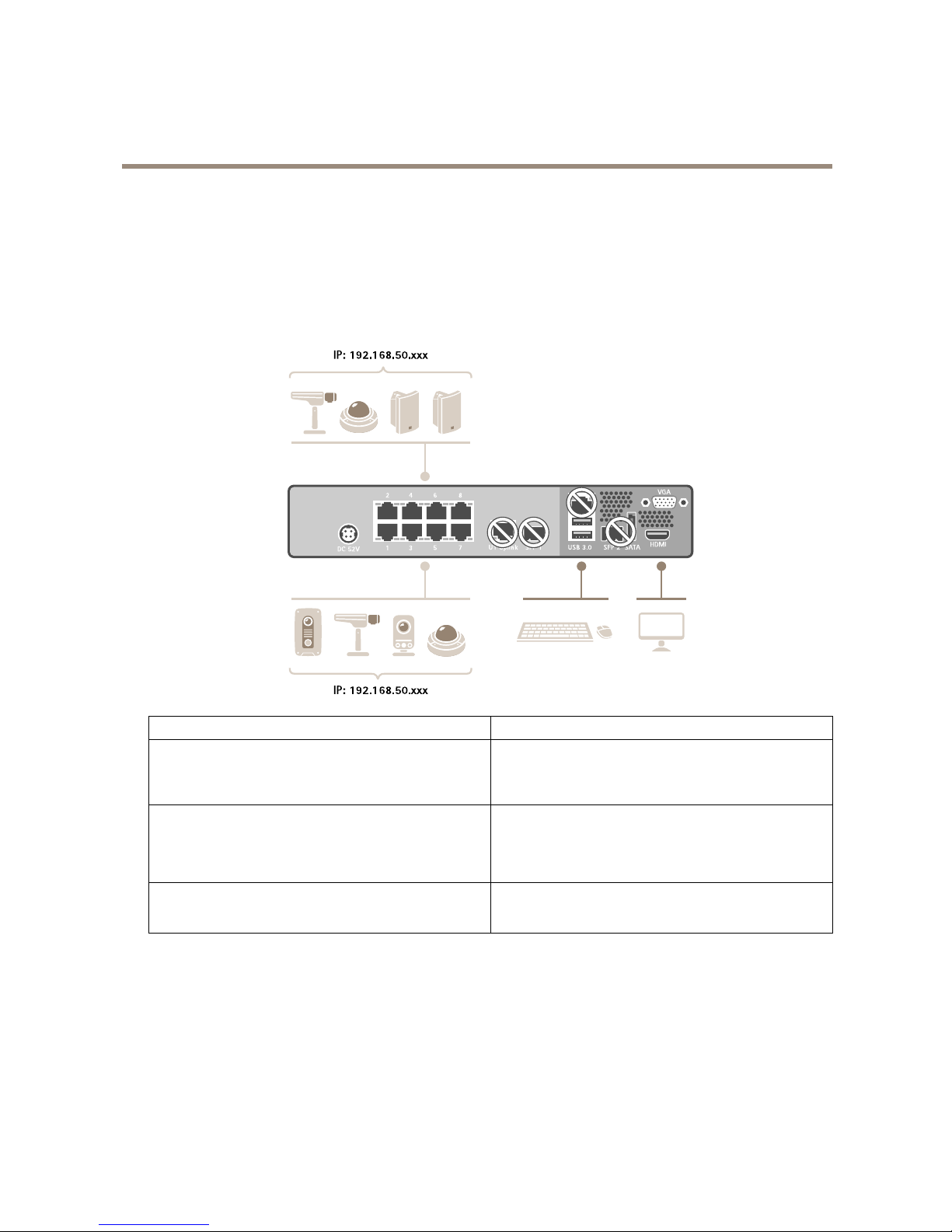
UseAXISCameraStationS20Applianceinanindependentsurveillancenetwork
Youcancreateanindependentsurveillancenetworkwhichhasnointerconnectivitytoanotherexternalnetwork.Thissetupisabasic
plugandplayinstallation.Thebuilt-inswitch’sDHCPserverisenabledbydefault.AssoonasyouplugthecamerasintothePoE
ports,thecameraswillpoweronandobtainanIPaddressandbeaccessibleviaAXISCameraStation.
Difcultylevel
Basic
Benets
Dedicatedsurveillancenetworkwithnointerconnectivityto
anotherexternalnetwork
Plugandplayinstallation
LimitationsBandwidth
PoEbudget
Noremoteaccess
Actionsneeded
Changethedefaultpasswordforthebuilt-inswitch.
RegistertheAXISCameraStationlicense.
4
Page 5

AXISCameraStationS20ApplianceSeries
Setupexamples
Connectorsused
PoEenablednetworkconnectors,port1—8
USB3.0connectorx2(forkeyboardandmouse)
VGAorHDMIconnector
ConnectorsNOTused
U1switchuplink
SFP1switchuplink
U2servernetwork
SFP2servernetwork
eSATAconnector
USB2.0connectorx2(frontpanel)
UseAXISCameraStationS20Applianceinanexistingnetwork
Youcancreateasurveillancenetworkwithinanexistingnetwork.Thismeansthatthesurveillancenetworkisseparatedfrom
theexistingnetwork.
Difcultylevel
Advanced
BenetsAbilitytouseanAXISCameraStationClienttoconnectto
S2008overthenetwork.
Networksegregation.
LimitationsMayrequireyoutofollowcorporatenetworkpolices.
5
Page 6

AXISCameraStationS20ApplianceSeries
Setupexamples
Actionsneeded
Changethedefaultpasswordforthebuilt-inswitch.
RegistertheAXISCameraStationlicense.
Connectorsused
PoEenablednetworkconnectors,port1—8
U2servernetwork(forconnectiontonetwork)
(Optional)USB3.0connectorx2(forkeyboardandmouse)
(Optional)VGAorHDMIconnector
ConnectorsNOTused
U1switchuplink
SFP1switchuplink
SFP2servernetwork
eSATAconnector
USB2.0connectorx2(frontpanel)
6
Page 7

AXISCameraStationS20ApplianceSeries
Managethebuilt-inswitch
Managethebuilt-inswitch
Aboutthebuilt-inswitch
TheAXISCameraStationS20ApplianceSeriescomeswithanintegratedPoweroverEthernet(PoE)switch.Youcongureandmanage
thebuilt-inswitchfromawebpage.
Thepurposeoftheswitchistosegregatetrafconthenetworksothatsecuritycamerasandrelatedtrafcmanagedbytheswitch
(PoEportsandU1networkconnections)arenotsharedwithothernetworks.
Theswitch’spowermanagementfollowtheserules:
•Eachportreservespoweraccordingtotheconnectedpowereddevice’sPoEclass.
•Iftheactualpowerconsumptionforagivenportexceedsthereservedpowerforthatport,itwillshutdown.
•Portswillshutdownwhentheactualpowerconsumptionforallportsexceedsthetotalamountofpowerthatthe
powersupplycandeliver .Theportsarethenshutdownaccordingtotheportsprioritywherealowerportnumber
meanshigherpriority.
Howtoopentheswitch'swebpage
1.Fromyourdesktop,opentheGetStartedapplicationandgotoPoESwitch.
2.ClickGotoPoEswitchwebsite.
3.Loginwithusernameadminandpasswordsystem.
Thersttimeyouloginyou’llbepromptedtochangethepassword.
Note
Youcanalsoopentheswitch’swebpageviaabrowser:entertheswitch’sIPaddress192.168.50.1inthebrowser’s
addresseld.
Howtoreboottheswitch
Important
Whiletheswitchreboots,allconnecteddeviceswilltemporarilyloseconnectionwiththeswitch(includingPoE).
1.Opentheswitch’swebpage.
2.GotoAdmin>Maintenance.
3.ClickRebootswitch.
Howtoimprovesecurityforusedports
YoucanlockaMACaddresstoaportsothatonlytrafccomingfromthatMACaddresswillpass.Thisimprovessecurityandprevents
unauthorizedusersfromconnectingalaptoporotherdevicestothesecuritynetwork.
1.Opentheswitch’swebpage.
2.GotoACL.
3.ForeachportyouwanttolocktheMACaddressfor ,clickACLenabled.
Note
ClickEnablealltolocktheMACaddressesforallportsatonce.
7
Page 8

AXISCameraStationS20ApplianceSeries
Managethebuilt-inswitch
Howtoimprovesecurityforunusedports
Youcandisableportsthatyoudonotuse.Thisimprovessecurityandpreventsunauthorizedusersfromconnectingalaptopor
otherdevicestothesecuritynetwork.
1.Opentheswitch’swebpage.
2.GotoOverview>Portstatus.
3.Foreachportyouwanttodisable,turnoffPortenabled.
Howtoconguretheswitch'sIPaddress
Youcanchangetheswitch’sIPaddressbutformostcamerainstallationswerecommendtousethedefaultsettings.Thereasonfor
thisisthatasurveillancenetworkisnormallyisolatedfromothernetworks,forexampleacorporateLAN.Inthiscase,youwould
onlyusethesurveillancenetworktomanageandcollectsurveillancedevicesanddatafromthevideomanagementsoftware
installedontheserver.
Important
MakesureyourecordthenewIPaddress.Ifyou’veforgottenthenewIPaddress,contactAxissupport.
Note
Thefactorydefaultsettingsare:astaticIPconnectionwithaddress192.168.50.1andasubnetmaskwithaddress
255.255.255.0.
1.Opentheswitch’swebpage.
2.GotoNetwork>Conguration.
3.EnterIPaddress,Subnetmask,Gateway,DNS1andDNS2.
4.ClickSave.
5.Reboottheswitch.
HowtoconguretheDHCPserver
Important
Iftheswitch’sDHCPserverisenabledandtheAXISCameraStationS20Applianceisconnectedtoanexternalnetwork
withitsownDHCPserverviatheU1orSFP1connectors,youwillhaveIPaddressconicts.Thismightresultinthe
corporatenetworknotworking.
YoucanconguretheswitchtouseitsinternalDHCPserverforassigningIPaddressestoconnecteddevices.WhenyouusetheU1
connectiontoallowdevicestoaccessorbeingaccessedbyexternalapplication,youmustspecifythegatewayandDNSaddresses.
1.Opentheswitch’swebpage.
2.GotoNetwork>DHCPserver.
3.EnterStartIPaddress,EndIPaddress,Subnetmask,Gateway,DNS1,DNS2andLeaselength.
4.ClickSave.
5.Reboottheswitch.
8
Page 9

AXISCameraStationS20ApplianceSeries
Managethebuilt-inswitch
Howtoresettheswitchtofactorydefaultsettings
Note
Ifyou’veforgottenyournewIPaddressorpasswordandcan’taccesstheswitch,contactAxissupport.
1.Opentheswitch’swebpage.
2.GotoAdmin>Maintenance.
3.ClickResettofactorydefault.
4.Reboottheswitch.
Howtochangetheswitch'spassword
Youcanchangethedefaultpasswordtoapasswordyouchooseyourself.
Important
Makesureyouselectapasswordyouremember.Ifyou’veforgottenthenewpassword,contactAxissupport.
1.Opentheswitch’swebpage.
2.GotoAdmin>Security.
3.EnterUsernameandPassword.
4.EntertheNewpasswordandconrmit.
5.ClickSave.
6.Reboottheswitch.
Howtobackuptheswitch'ssettings
Note
Theusernameandpasswordarenotincludedinthebackuple.
1.Opentheswitch’swebpage.
2.GotoAdmin>Maintenance.
3.ClickBackupsettings.
4.Savethe.gzle.
Howtorestoretheswitch'ssettingstopreviousbackup
Note
Torestoretheswitch’ssettingsyoumustpreviouslyhavecreatedabackuple.
1.Opentheswitch’swebpage.
2.GotoAdmin>Maintenance.
3.ClickBrowse.
4.Selecttheappropriate.gzle.Makesurethatthemodelnameandserialnumberinthelenamematchyourdevice.
5.ClickRestore.Oncethesettingsarerestored,theswitchwillautomaticallyreboottoacceptallrestoredchanges.
9
Page 10

AXISCameraStationS20ApplianceSeries
Managethebuilt-inswitch
Theusernameandpasswordarenotincludedintherestorele.Youhavetologintotheswitch’swebpagewiththesame
credentialsasbeforeyourestoredthesettings.
HowtoaddaVLAN
WerecommendtocreateaseparateVLANforendpointsotherthandevicesbelongingtothesurveillancesystem.Eachmemberof
theVLANcanonlycommunicatewithothermembersoftheVLANwiththeexceptionoftheswitch’swebpage.EveryVLAN,ifits
endpointisenabledtoincludeanIPaddressinthesamesubnetastheswitch’swebpage,canbrowsetotheswitch’swebpage(ifyou
havethecorrectcredentials).Inthisway,switchadministratorscanneverbelocked-outfromtheswitch.
Example
YoucouldcreateasecondVLANforIPphones,printers,orcomputerssharingthesameswitch.ThedefaultVLAN(VLAN1)wouldthen
beusedstrictlybythesecuritysystem.Inthisway,youpreventtrafcfromaseparatenetworkwithadifferentpurposetomingle
withorgainaccesstosecurityequipmentoraccesssecuritytrafcandviceversa.
Note
Firmwareversion1.4.5.418orhighersupportsVLAN.
1.Opentheswitch’swebpage.
2.GotoVLANandclickAdd.
3.Selectwhichport,uplinkorCPUconnectionsyouwanttoaddtothenewVLAN.
Eachport,uplink,orCPUconnectioncanonlybelongtooneVLANatatime.
4.(Optional)ClicktheVLANnameeldandtypeadescription,forexample“BuildingA,2ndoorcameras”.
5.Reboottheswitch.
Howtoencrypttrafctotheswitch'swebpage
YoucanimplementHTTPStoaddatransportlayerencryption(TLS)ondatathatpassesfromthebrowsertotheswitch.Thisis
importantwhenyouresettheswitch’spasswordtopreventnon-authorizedusersfromobtainingtheswitch’spasswordthrough
unencryptedtrafc.
ThedevicesupportsthreemodesforimplementingHTTPS:HTTPonly,HTTPorHTTPS(basedontheURLselected),orHTTPSonly.
Ifyouwanttoencrypttrafc,werecommendtodisableHTTPandonlyuseHTTPS.
1.Opentheswitch’swebpage.
2.GotoHTTPS>Managecerticate.
3.Generateaself-signedcerticateoruploadmatchingbundle,certicate,andkeyles.
BeforeyoucanactivateHTTPS,theswitchveriesthatthesearevalidandthatthelesmatch.
4.GotoAdministration.
5.SelectHTTPSanddisableHTTP.
6.Reboottheswitch.
Overviewtab
IntheOverviewtab,youndinformationaboutthedevice,resourceusageandportstatus.
PaneFunctionDescription
Systeminformation
ModelThedevice’smodelname.
10
Page 11

AXISCameraStationS20ApplianceSeries
Managethebuilt-inswitch
SerialnumberThedevice’sserialnumber.Canbeusefulformaintenanceorwhenyou
needtotrackindividualdevices.
Firmwareversion
Thermwareversioninstalledonyoudevice.Canbeusefultodetermine
whetheryouneedtoupgradetheswitchrmware.
PortcountThenumberofnetworkportsthedevicesupports,includingacorporate
uplinkport.
MaxPoE
Thetotalpoweravailableforpoweroverethernet(PoE)devices.
ResourceusageTotalPoEusage
Displayshowmuchpower(inwatts)thePoEdevicesconnectedtothe
switchareusing.
Oncethemaximumpowerhasbeenreached,thedevicescannotprovide
anyfurtherpower.
PoEstatusIndicateswhetherPoEisenabledandhowmanyportshavebeenenabled
tosupportPoE.
ACLstatus
IndicateswhetherACL(AccessControlList)isenabledandhowmany
portsareenabledwiththisaddedsecurityfeature.
ACLbindsaspecicMACaddresstoaport,preventingtrafc(sentor
received)fromdeviceswithotherMACaddresses.
PortstatusPort#Theportnumbertowhichtheselecteddeviceisconnected.
LinkstateUpindicatesthatadeviceisconnectedtothisport.
Downindicatesthatnodeviceisconnected.
LinkspeedThecurrentnegotiatedlinkspeedforeachport.
TransmitrateAnoverviewoftrafcloadoneachportshowingtheaveragedataratein
megabitspersecondforoutbounddataontheport.
ReceiverateAnoverviewoftrafcloadoneachportshowingtheaveragedataratein
megabitspersecondforinbounddataontheport.
Powerdraw
Theaveragepower(inwatts)beingdrawnviaPoEbythedeviceattached
totheport.
PoEstatusDisplaysifPoEisenabledordisabledforeachport.
ACLstatusDisplaysifACLisenabledordisabledforeachport.
Portenabled
Allowsyoutoviewandchangetheenabledordisabledportstatus(the
port'sabilitytoreceiveorsenddata).Thisisseparatefromthelink
statusandPoE.
AdisabledportmayormaynotstillbeprovidingpowertoaPoEdevice,
anditmaystillbephysicallyconnectedtodevice,butitcannotbeused
tosendorreceivedata,eventhoughitslinkstatusmaystillbeUpand
theattacheddeviceisstilldrawingpower.Disablingtheportprevents
anydevicefromaccessingtheswitchornetwork.Portsthatarenotin
useshouldbedisabledforincreasedsecurity .
Uplink1
IfU1orSFP1containsanactiveconnectionitwilldisplayUp.
IfU1orSFP1containsannon-activeconnectionitwilldisplayDown.
Themaximumlinkspeedandaveragetransmitandreceivedatain
megabitspersecondhelpyouunderstandtrafcpatternsandverify
operationalstatusofassociatedapplications.
11
Page 12

AXISCameraStationS20ApplianceSeries
Managethebuilt-inswitch
PoEtab
InthePoEtab,youndformationaboutthesetupandstatusofpoweroverEthernet(PoE)foreachportandforthePoEenabled
devicesasawhole.Thisdataisusefulforsetting,enabling,disabling,andmanagingtheswitch’spowerbudget.
PaneFunctionDescription
PortstatusPort#Theapplianceportnumbertowhichtheselecteddeviceisconnected.
LinkstateUpindicatesthatadeviceisconnectedtothisport.
Downindicatesthatnodeviceisconnected.
PoEmodeTypeofdevicetheswitchhasdetected.Thisisnotcongurable,the
valuesareassignedbytheswitchbasedonitsinteractionandpower
drawoftheconnecteddevice.
PoEmodevaluesareeitherATorAF.ThesevaluesrefertotheIEEE
802.3atorIEEE802.3afstandards.
PoEclassTypeofdevicetheswitchhasdetected.Thisisnotcongurable,the
valuesareassignedbytheswitchbasedonitsinteractionandpower
drawoftheconnecteddevice.
PoEClassvaluesrangefrom0to4andcorrespondtothefollowing
propertiesasdenedintheIEEEstandard:
Class
Usage
ClassicationCurrent
(mA)
Power
Range
(watts)
Class
Description
0
Default
0-40.44-12.94
Classicationunimplemented
1
Optional
9-120.44-3.84
Verylow
power
2
Optional
17-203.84-6.49
Lowpower
3
Optional
26-306.49-12.95
Midpower
4
Validfor802.3at
(Type2)devices;
notallowedfor
802.3afdevices
36-4412.95-
25.50
Highpower
PowerdrawTheaveragenumberofwattstheconnecteddeviceisconsuming.
PowerlimitDisplaysadefaultlimitbasedonthePoEmodeandclass.
PoEenabledAllowsyoutoviewandchangethePoEenabledordisabledstatustoturn
thePoEtothedeviceonorofffordevices.
DevicesrequiringPoEwillbeturnedoffwhendisabledandthelinkstate
willchangetoDown.
PoEadministrationWattsscale
Theamountofpower(inwatts)drawnbyalldevicescurrentlyconnected
totheswitch.
TotalPoEusage
Thetotalpowerconsumed(inwattsandpercentages)byallconnected
devices.
Thisinformationishelpfulwheninstallingdevicesandverifyingyour
powerbudget.
12
Page 13

AXISCameraStationS20ApplianceSeries
Managethebuilt-inswitch
PortsenabledThenumberofportsthatarecurrentlyenabledfordataprovidingpower
overEthernet.
MasterPoEAllowsyoutoenableordisablePoEforallportsinonecommand.
ACLtab
IntheACLtab,youndinformationabouttheaccesscontrollist(ACL)settings.InthistabyoucanforexamplelockaMACaddress
toaportsothatonlytrafccomingfromthatMACaddresswillbepassed.Thisimprovessecurityandpreventsunauthorizedusers
fromattachingalaptoporotherdevicestothesurveillancenetwork.
PaneFunctionDescription
AdministrationPortsenabled
ThenumberofportsboundtoaspecicMACaddressusingACL.
MasterACLEnablesordisablesACLforallportswithaboundedMACaddress.Only
portswithadiscoveredMACaddressorboundedaddresswillbeaffected.
PortstatusPort#Theportnumbertowhichtheselecteddeviceisconnected.
LinkstateUpindicatesthatadeviceisconnectedtothisport.
Downindicatesthatnodeviceisconnectedtothisport
DiscoveredMAC
addresses
TheswitchautomaticallydetectstheMACaddressofanydevice
connectedtotheportanddisplaysithere.Datatrafcwillonlybe
allowedtoorfromthisMACaddress.
BoundMACaddressesEnablingACLwillbindtheporttothediscoveredMACaddress.Noother
devicewillbeabletocommunicateonthisport.WhenyouenableACL,
ifthereisaDiscoveredMACAddress,itwillmovetotheBoundMAC
Addresscolumn,bindingittothisport.
UnauthorizedMAC
addresses
DisplaystheMACaddressofanyunauthorizedcameraorothernetwork
deviceattemptingtosendtrafcoveranACLenabledport.
PoEstatus
DisplaysthecurrentPoEstatus(enabledordisabled).
ACLenabledWhenyouenableACL,ifthereisaDiscoveredMACAddressitwillmove
totheBoundMACAddresscolumn,bindingittothisport.Disabling
ACLclearstheBoundMACAddressvaluesoyoumaybindadifferent
devicetothisport.
VLANtab
IntheVLANtab,youndinformationabouthowtoaddandmanagevirtualLANs(VLAN).
FunctionDescription
IDTheautomaticallygeneratednameoftheVLAN.
VLANnameThemanuallyentereddescriptionoftheVLAN.
Selectall
AddsallavailableportstotheVLAN.
1–8
1—16
1—24
Theavailableports.Thenumberdependonthedevicemodel.
U1Uplink1
CPUNetworkconnectiontotheserver’sCPU.
13
Page 14

AXISCameraStationS20ApplianceSeries
Managethebuilt-inswitch
DHCP
Theswitch’sDHCPserverisonlyavailableonVLAN1(default).DHCPwilldisplayasenabled
oncetheswitch’sDHCPserverisactivatedintheNetworktab.
IfotherVLANsrequireDHCPaddressassignment,anexternalDHCPservermustbeprovided
andaccessiblewithinthenetworksofVLANs2orgreater.
DeleteWhenyoudeleteaVLAN,anymembersofthatVLANareimmediatelyreturnedtothe
membershipofVLAN1,thedefaultVLAN.
HTTPStab
IntheHTTPStab,youndinformationaboutcerticatesandHTTPSsettings.
PaneFunctionDescription
AdministrationHTTPTurnonoroffHTTP.
HTTPSTurnonoroffHTTPS.
Currentcerticate
Version
Serialnumber
Signaturealgorithm
Validfrom
Validto
Subject
Issuer
Fingerprint
Informationabouttothecurrentlyinstalledcerticate(third-partyor
self-signed),ifany.
Toupdatecerticatesoranyoftheinformationinthispaneoncenew
certicatesorkeysareprovided,youmustreboottheswitch.Once
rebooted,theswitchwilldisplaythemostcurrentcerticateinformation.
Managecerticate
CAbundlele
Certicatele
Privatekeyle
Selectcountry
Organization
Commonname
Theseeldsallowyoutogenerateaself-signedcerticateorupload
matchingbundle,certicate,andkeyles.
Networktab
IntheNetworktabyoucanconguretheIPaddressoftheswitchandmanagethebuilt-inDHCPserver.TheDHCPservercontrols
theassignmentofIPaddressesdevicesconnectedtotheswitch’sports.
PaneFunctionDescription
Conguration
IPaddressTheIPaddressoftheU1switchconnection.
Youcanopentheswitch’swebpagethroughthisaddress
Subnetmask
ThesubnetmaskoftheU1switchconnection.
Gateway
ThegatewayforaccessingtheU1switchconnection.
DNS1
Theprimarydomainnameserverusedbytheswitch.
DNS2
Analternatedomainnameserverusedbytheswitch.
14
Page 15

AXISCameraStationS20ApplianceSeries
Managethebuilt-inswitch
DHCPserver
Enabled
ThestatusoftheDHCPserver.
WhentheDHCPserverisdisabled,youmustassignIPaddressesmanually
tothecamerasoruseanexternalDHCPserveraccessibleviatheU1
networkconnectionforIPassignment.
StartIPaddress
EndIPaddress
WhenDHCPisenabled,youcanchooseaStartIPaddressandEndIP
addressrangeforassignmentofattacheddevices
Subnetmask
ThesubnetmaskoftheU1switchconnection.
Gateway
ThegatewaytoaccesstheU1switchconnection.
DNS1
Theprimarydomainnameserverusedbytheswitch.
DNS2
Analternatedomainnameserverusedbytheswitch.
Leaselength
ThesuggestedlengthoftimeinminutesthattheDHCPserverwillusefor
potentiallyreassigningitspoolofdynamicIPaddresses.Theminimum
leaselengthis60minutes.
Admintab
IntheAdmintab,youndinformationaboutthermwareversion.Inthistabyoucanalsochangethepassword,backupsettings
andreboottheswitch.
PaneFunctionDescription
Security
Username
Password
Newpassword
Conrmnewpassword
Theseeldsallowyoutosetthepasswordfortheswitchadministrator.
Theswitchonlyhasoneuser:admin.
Thefactorydefaultpasswordissystem.
FirmwareVersionTheinstalledrmwareversion.
UpgradermwareAllowsyoutoupdatethermwaretoanewversion.
MaintenanceResettofactorydefaultResetsallswitchsettingstofactorydefaultvalues.
RebootswitchRebootstheswitch.Whilerebooting,alldeviceswilltemporarilylose
connectionwiththeswitch(includingPoE).
Backupsettings
StoresabackupofyoursettingsinaleintheDownloadsfolderof
yourbrowser.
RestoresettingsAllowsyoutoselectasavedbackupletorestoresettings.
15
Page 16

AXISCameraStationS20ApplianceSeries
Productoverview
Productoverview
FrontPanelAXISCameraStationS20Series
1
USB2.0connectorx2(notused)
2
SystempowerLED
3
DiskactivityLED
4
StatusLEDs,PoEport1–8,1–16or1–24
16
Page 17
AXISCameraStationS20ApplianceSeries
Productoverview
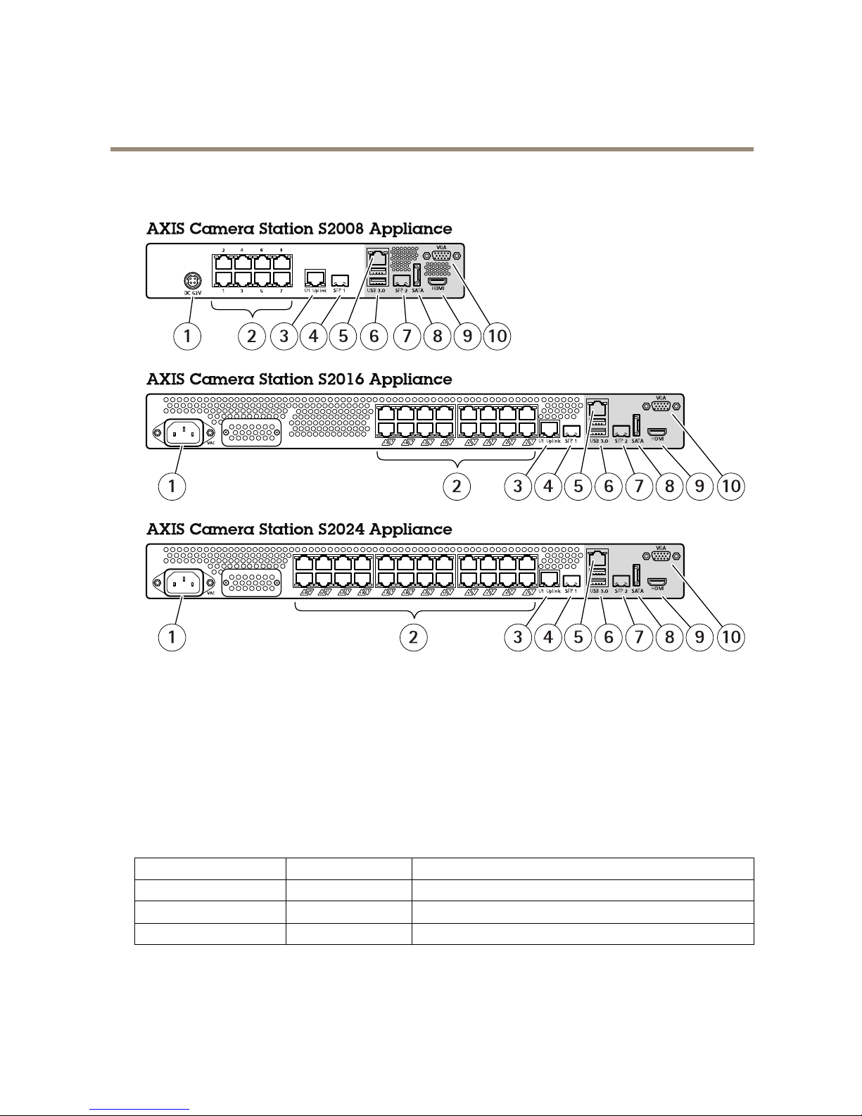
BackPanelAXISCameraStationS20Series
1
Powerconnector
2
PoEenablednetworkconnectors,port1–8,1–16or1–24
3
U1switchuplink,RJ45connector
4
SFP1switchuplink,SFPconnector
5
U2servernetwork,RJ45connector
6
USB3.0connectorx2
7
SFP2servernetwork,SFPconnector
8
eSATAconnector
9
HDMIconnector(audiooutputsupported)
10
VGAconnector
LEDIndicators
LEDindicator
Color
Indication
SystemPowerLEDSteadygreenOn
DiskactivityFlashingyellow
Read/write
PoEports
Steadyred
Portconnected
17
Page 18

UserManualVer.M2.15
AXISCameraStationS20ApplianceSeries
Date:November2017
©AxisCommunicationsAB,2016-2017
PartNo.T10084515
 Loading...