

Page 1

AXIS Panorama PTZ
Network Camera
User’s Manual
Page 2

2
AXIS Panorama PTZ User’s Manual
About This Document
This document is intended for administrators and users of
the AXIS Panorama PTZ Network Camera, and is applicable
for firmware release 2.34. This document should be used as
a supplement to the Installation Guide and online
information available via the Web-based interface. Later
versions of this document will be posted to the Axis
Website, as and when required.
Safety Notices Used In This Manual
Caution! - Indicates a potential hazard that can damage the
product.
Important! - Indicates a hazard that can seriously impair
operation.
Do not proceed beyond any of the above notices until you
have fully understood the implications.
Intellectual Property Rights
Axis AB has intellectual property rights relating to
technology embodied in the product described in this
document. In particular, and without limitation, these
intellectual property rights may include one or more of the
patents listed at http://www.axis.com/patent.htm and one
or more additional patents or pending patent applications
in the US and other countries.
Legal Considerations
Camera surveillance can be prohibited by laws that vary
from country to country. Check the laws in your local
region before using the AXIS Panorama PTZ for
surveillance purposes.
Electromagnetic Compatibility (EMC)
This equipment generates, uses, and can radiate radio
frequency energy, and if not installed and used in
accordance with the instruction manual, may cause
interference to radio communications. Shielded cables
should be used to ensure compliance with EMC standards.
USA - This equipment has been tested and found to
comply with the limits for a Class A computing device
pursuant to Subpart B of Part 15 of FCC rules, which are
designed to provide reasonable protection against such
interference when operated in a commercial environment.
Operation of this equipment in a residential area is likely to
cause interference, in which case the user at his/her own
expense will be required to take whatever measures may be
required to correct the interference.
Europe - This digital equipment fulfills the requirements
for radiated emission according to limit B of EN55022/1994,
and the requirements for immunity according to EN55024/1998
residential, commercial, and light industry.
Liability
Every care has been taken in the preparation of this manual; if
you detect any inaccuracies or omissions, please inform your
local Axis office. Axis Communications AB cannot be held
responsible for any technical or typographical errors and
reserves the right to make changes to the product and manuals
without prior notice. Axis Communications AB makes no
warranty of any kind with regard to the material contained
within this document, including, but not limited to, the implied
warranties of merchantability and fitness for a particular
purpose. Axis Communications AB shall not be liable nor
responsible for incidental or consequential damages in
connection with the furnishing, performance or use of this
material.
Trademark Acknowledgments
Acrobat, Adobe, Boa, Ethernet, IBM, Internet Explorer, LAN
Manager, Linux, Macintosh, Microsoft, Netscape Navigator,
OS/2, Scalado, UNIX, Windows, WWW are registered trademarks
of the respective holders. Java and all Java-based trademarks
and logos are trademarks or registered trademarks of Sun
Microsystems, Inc. in the United States an d other countries. Axis
Communications AB is independent of Sun Microsystems Inc.
Support Services
Should you require any technical assistance, please contact
your Axis reseller. If your questions cannot be answered
immediately, your reseller will forward your queries through
the appropriate channels to ensure a rapid response. If you are
connected to the Internet, you can:
• Download user documentation and firmware updates.
• Find answers to resolved problems in the FAQ database.
Search by product, category, or phrases.
• Report problems to Axis support staff by logging in to your
private support area.
Visit the Axis Support Web at www.axis.com/techsup/
AXIS Panorama PTZ Network Camera User’s
Manual
Revision 1.0
Part no: 20188
Dated: June 2003
Copyright © Axis Communications AB, 2003
AXIS COMMUNICATIONS
<Product Name> Quick User’s Guide
Page 3

AXIS Panorama PTZ User’s Manual
Table of Contents
Overview. . . . . . . . . . . . . . . . . . . . . . . . . . . . . . . . . . . . . . . . . . . . . . . . . . . . . . . . 4
Features and Benefits . . . . . . . . . . . . . . . . . . . . . . . . . . . . . . . . . . . . . . . . . . . . . . . . . . 5
Physical Description . . . . . . . . . . . . . . . . . . . . . . . . . . . . . . . . . . . . . . . . . . . . . . . 7
Front Panel . . . . . . . . . . . . . . . . . . . . . . . . . . . . . . . . . . . . . . . . . . . . . . . . . . . . . . . . . . 7
Rear Panel . . . . . . . . . . . . . . . . . . . . . . . . . . . . . . . . . . . . . . . . . . . . . . . . . . . . . . . . . . . 8
Assembling the AXIS Panorama PTZ . . . . . . . . . . . . . . . . . . . . . . . . . . . . . . . . . . . 9
Hardware Inventory . . . . . . . . . . . . . . . . . . . . . . . . . . . . . . . . . . . . . . . . . . . . . . . . . . . . 9
The Mounting Assembly . . . . . . . . . . . . . . . . . . . . . . . . . . . . . . . . . . . . . . . . . . . . . . . . 9
Network Installation . . . . . . . . . . . . . . . . . . . . . . . . . . . . . . . . . . . . . . . . . . . . . . 10
Configuration . . . . . . . . . . . . . . . . . . . . . . . . . . . . . . . . . . . . . . . . . . . . . . . . . . . 12
Minimum Configuration . . . . . . . . . . . . . . . . . . . . . . . . . . . . . . . . . . . . . . . . . . . . . . . 12
Configuring the Panorama Application . . . . . . . . . . . . . . . . . . . . . . . . . . . . . . . . . . . . 13
3
Using the Panorama PTZ Tools . . . . . . . . . . . . . . . . . . . . . . . . . . . . . . . . . . . . . . . . . . . 13
Setting up Preset Postions . . . . . . . . . . . . . . . . . . . . . . . . . . . . . . . . . . . . . . . . . . . . . . 14
The Administration Tools . . . . . . . . . . . . . . . . . . . . . . . . . . . . . . . . . . . . . . . . . . . . . . . 15
Reinstating the Factory Default Settings . . . . . . . . . . . . . . . . . . . . . . . . . . . . . . . . . . . 18
Appendix A - Lenses and Focusing . . . . . . . . . . . . . . . . . . . . . . . . . . . . . . . . . . . 19
Manual Focusing . . . . . . . . . . . . . . . . . . . . . . . . . . . . . . . . . . . . . . . . . . . . . . . . . . . . . 19
Focusing using the Focus Assistant . . . . . . . . . . . . . . . . . . . . . . . . . . . . . . . . . . . . . . . 20
Appendix B - Troubleshooting. . . . . . . . . . . . . . . . . . . . . . . . . . . . . . . . . . . . . . . 22
Pinging Your IP Address . . . . . . . . . . . . . . . . . . . . . . . . . . . . . . . . . . . . . . . . . . . . . . . . 22
Problems, Possible Causes and Remedial Actions . . . . . . . . . . . . . . . . . . . . . . . . . . . . . 23
Appendix C - Other IP Setup Methods . . . . . . . . . . . . . . . . . . . . . . . . . . . . . . . . 25
Using the AXIS IP Installer . . . . . . . . . . . . . . . . . . . . . . . . . . . . . . . . . . . . . . . . . . . . . . 26
Appendix D - Upgrading the Firmware . . . . . . . . . . . . . . . . . . . . . . . . . . . . . . . . 27
Appendix E - Technical Specifications . . . . . . . . . . . . . . . . . . . . . . . . . . . . . . . . . 28
Index . . . . . . . . . . . . . . . . . . . . . . . . . . . . . . . . . . . . . . . . . . . . . . . . . . . . . . . . . 29
Glossary of Terms . . . . . . . . . . . . . . . . . . . . . . . . . . . . . . . . . . . . . . . . . . . . . . . . 30
Page 4

4
Overview AXIS Panorama PTZ User’s Manual
Overview
The AXIS Panorama PTZ Network Camera is a digital TCP/IP network camera kit that
includes 2 cameras with wide-angle lenses, a complete camera stand, and all of the
required networking connectivity for distributing images or live video over an intranet or
the Internet.
By mounting the 2 cameras on the special stand provided, the combination of the cameras
and the special software installed in them provides a lateral view of up to approximately
140 degrees. Special Pan, Tilt and Zoom controls are also provided, so that users can
quickly and easily steer the view to any point in the panorama.
The AXIS Panorama PTZ’s
built-in Web server allows
high-quality remote
surveillance images to be
viewed directly from any
browser on the network, and
provides full Web-based
control of the various
management and
configuration functions.
The AXIS Panorama PTZ can
be used in both indoor and
outdoor environments. When
used outdoors, the cameras
must be housed in a suitable
outdoor enclosure.
Use the camera for intruder
detection, process control,
industrial and public
surveillance, visual security,
image archiving, or any other application requiring remote monitoring.
The AXIS Panorama PTZ minimizes the need for costly and complex coaxial cabling - to
press your installation overheads and provide you with an advanced yet cost-effective
network imaging solution. None of the hidden accessories normally associated with digital
cameras are required.
Page 5

AXIS Panorama PTZ User’s Manual Overview
Features and Benefits
140 degrees of lateral view - The image stream from the AXIS Panorama PTZ features a wide
lateral display of almost 140 degrees and up to 65 degrees of tilt. The controls in the web
interface allow the image to be zoomed, tilted up and down and panned from right to left.
Multiple viewers can see any part of the panorama, independently of each other.
Full coverage all the time - The full field of view is constantly being covered. Even if a user is
zoomed in on a particular part of the view, images are still streamed from the whole
panorama, which is useful if you are recording (see below) from one particular part of the
view, but are viewing another part. This allows you to go back and view the part you
weren't looking at at the time of the event.
Continuous recording - The entire panorama can be recorded continuously, or after an alarm
event has occurred. Images are sent from the two cameras regardless of pan, tilt and zoom
actions by users, and in a non-panorama raw format. This is an advantage if images are to
be used as evidence in legal proceedings, as they are then in their original unaltered state.
Note that recording/upload must be configured for each camera.
5
Static Camera - The AXIS Panorama PTZ is defined as a static camera, that is, the camera
combination does not physically move when the panorama is viewed (there are no moving
parts at all). This can be significant when using the camera in a surveillance situation
where manoeverable cameras are prohibited.
Easy to Use - The AXIS Panorama PTZ requires no other special hardware or software. All
you need is Microsoft Internet Explorer 4.x or above. The AXIS Panorama PTZ has
complete plug-and-picture functionality - just assign an IP address and then view live
images in your browser.
Simple Installation and administration - Connects directly to Ethernet or Fast Ethernet
networks. Configuration and management via the product’s own Web-based
Administration Tools. Image control, time stamping and upload configuration are all
accessible from the tools.
Outdoor Use - When installed in an appropriate outdoor housing, the AXIS Panorama PTZ
can be used in outdoor applications.
Standard Image Format - The AXIS Panorama PTZ delivers high-quality pictures in standar d
JPEG format, one from each camera. These are then joined together by the Panorama
application.
Page 6

6
Overview AXIS Panorama PTZ User’s Manual
High Compression and Sensitivity - The fully configurable compression features afforded by
the AXIS ARTPEC chip allow a normal quality image to be compressed to around 8 kbytes.
Actual file sizes vary according to lighting conditions; although the product will work
even in dark environments - right down to 1 lux.
External Device Connection - Can be used with IR-sensors, switches and alarm relays.
Security - By using the AXIS Panorama PTZ’s multi-user password protection in
combination with a company Internet firewall, an administrator can decide whether
individuals, groups, the whole company or the whole world can access the camera.
Compression and Performance - With an adaptive frame rate dependent on the prevailing
lighting conditions, the AXIS Panorama PTZ delivers Motion-JPEG images at up to 15
images per second, as well as single JPEG images that feature user-defined compression
levels.
Linux Operating System - Including a Boa Web server, the Linux operating system provides a
stable platform for open-source development in future releases of the product. In
accordance with the GNU General Public License, Axis have published the kernel for this
product at http://developer.axis.com/
AXIS Technology - Axis renowned chipset technology is built upon an open architechture
streamlined to provide device connectivity independent of any file server. The AXIS
Panorama PTZ is driven by a powerful AXIS ETRAX 32-bit RISC processor and includes
the industry's first dedicated digital video remote monitoring compression chip - the AXIS
ARTPEC-1.
Network Camera Servers Developer's Pages - Axis maintains a specialist site for network camera
developers. New ideas and tools for software developers are often added. For more
information, please visit: www.axis.com
Other functions and features - The AXIS Panorama PTZ is intended primarily as a "live view"
panorama camera. The product may however contain other unsupported functions and
features not covered in this manual. For further information please see the AXIS 2110
User’s Manual, available from www.axis.com
Page 7
AXIS Panorama PTZ User’s Manual Physical Description
Physical Description
Please read the following information to familiarize yourself with the AXIS Panorama PTZ,
making particular note of where the connectors and indicators are located. This
information provides a useful reference during the installation of the product.
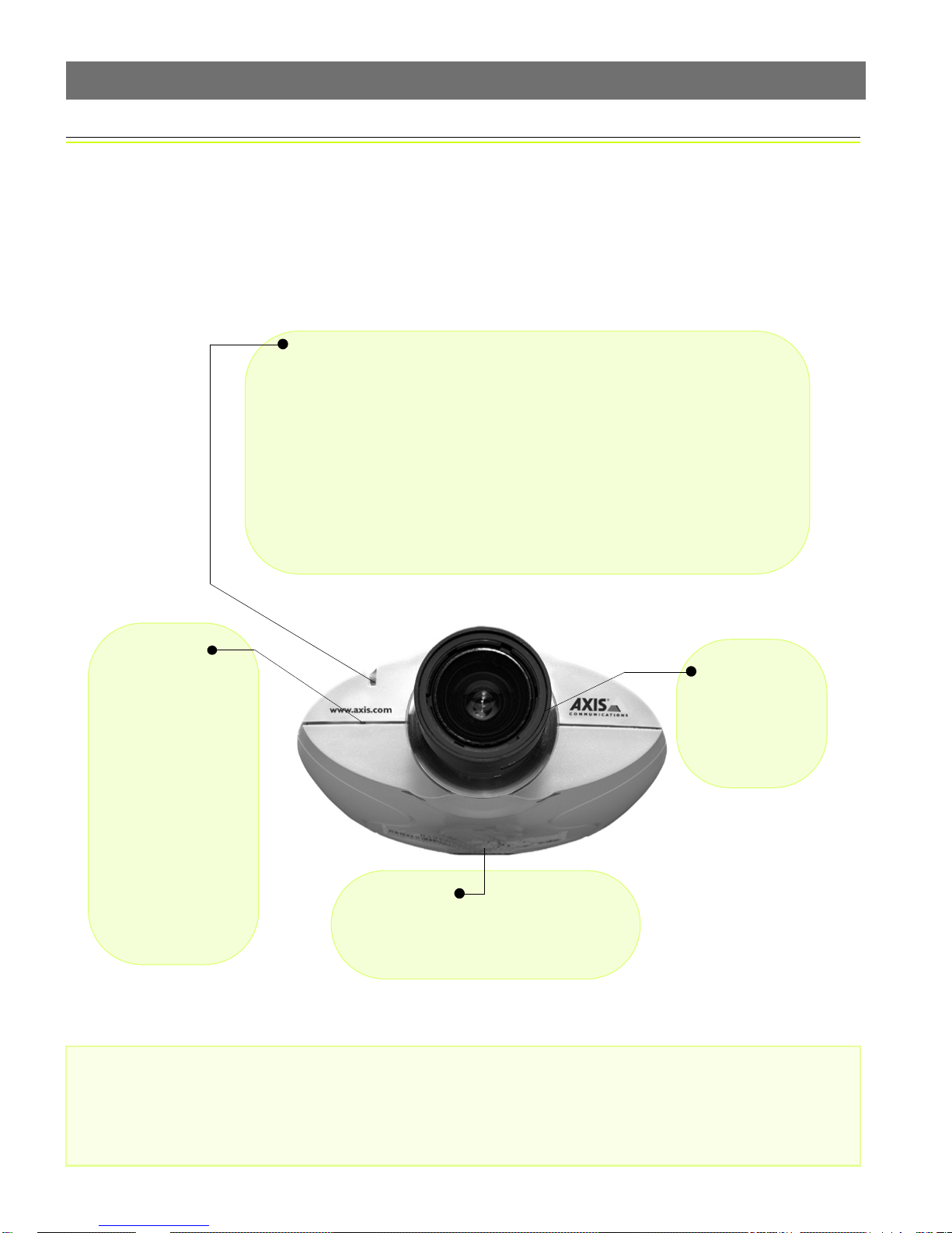
Front Panel
Status Indicator
Used in conjunction with the Focus Assistant, this multi-colored indicator can be configured for use as a local focusing aid (for further details please see page 19). Under
normal conditions however, the indicator shows the operational status of the camera,
as described below:
• green - indicates a healthy unit status.
• red - the indicator will display red only if a problem with the AXIS Panorama
PTZ has occurred. Refer to Appendix B - Troubleshooting.
Note: The Status indicator also displays orange when re-setting to the factory default
settings, as described on page 18. The Status Indicator can also be made to flash whenever images are displayed in a browser. See the on-line help for more information.
7
Control Button
Located to the left of
the lens assembly, this
button is recessed
within the product casing. Using a pointed
object, press the button
to restore the factory
default settings as
described in Reinstating
the Factory Default Settings, on page 18; or to
enable the Focus Assistant, as described in
Lenses and Focusing, on
page 19.
Serial Number
Located on the underside label of the AXIS
Panorama PTZ, the serial number is identical to the unit’s MAC/Ethernet addr e ss .
Lens Assembly
Manual iris
wide-angle lens,
with rotational
focus control.
Important!
Although the AXIS Panorama PTZ can be used both indoors and outdoors, it is important to note that the charged
coupled device (CCD) in the camera can become permanently damaged if exposed to too much direct sunlight or
halogen light. It is therefore important that the Adjustment Ring is not set fully open when installing the camera in
bright light conditions. The Axis warranty does not cover CCD damage caused by prolonged exposure to strong light.
To use the product outdoors, it must be housed within a proper outdoor enclosure.
Page 8
8
Physical Description AXIS Panorama PTZ User’s Manual
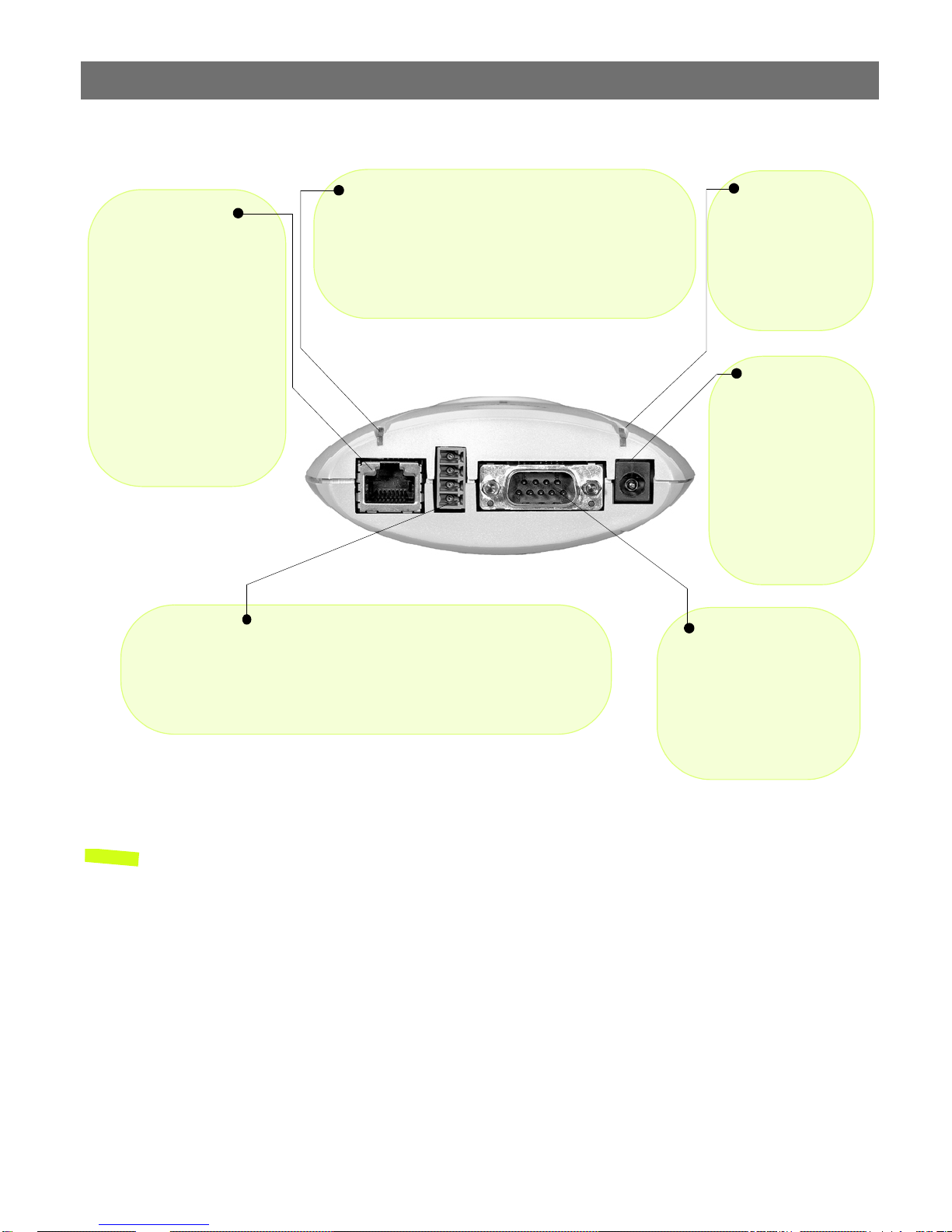
Rear Panel
Network Indicato r
Network Connector
The AXIS Panorama PTZ
connects 10/100 Mbps
Ethernet networks via a
twisted pair category 5
cable (10baseT and
100baseTX), terminated
using a standard RJ-45
connector. The AXIS Panorama PTZ detects the
speed of the local network
segment and varies the
speed of data communication accordingly.
I/O Connector
Provides the physical interface to a digital output, and a single digital
photo-coupled input that is used for connecting a variety of external alarm
devices to the AXIS Panorama PTZ; including, IR-sensors, switches and
alarm relays. For more information on using these devices, please see the
AXIS 2110 User’s Manual.
After completion of the startup and self test routines, this
multi-colored indicator flashes as follows:
• yellow - activity on a 10Mbps network
• green - activity on a 100Mbps network
• red - no physical connection to the network
Power Indicator
Normally lit when
power is applied. If
not lit, or if flashing,
there is a problem
with the external
power source.
Power Supply
Connector
A single Jack socket
(PS-D) for connection
of AXIS Panorama PTZ
power supply. The terminal block connector
provides an auxiliary
connection point for
AC or DC power to the
unit.
RS-232 Serial
Connector
The serial connector provides the RS-232 interface
for connecting a modem or
the AXIS 2191 Audio Module (these functions are
not supported.)
Note: The power adapter supplied with your AXIS Panorama PTZ is country-specific. Please
check that the type you are using is correct.
Page 9
AXIS Panorama PTZ User’s Manual Assembling the AXIS Panorama PTZ
Assembling the AXIS Panorama PTZ
The information provided in this section will help you unpack and assemble the product
correctly. Please contact your dealer if anything is missing or damaged.
Hardware Inventory
The following items are supplied with the AXIS Panorama PTZ:
Item Description/type Quantity
Network Camera AXIS Panorama PTZ Network Camera 2
Power adapter PS-D 2
Power extension cable 3.3 meters 2
Camera Stand - 1
Mounting bracket - 1
Printed Materials AXIS Panorama PTZ Installation Guide 1
AXIS Warranty 1
9
Note: The power supply for your AXIS Panorama PTZ is country-specific. Please check that the type
you are using is correct.
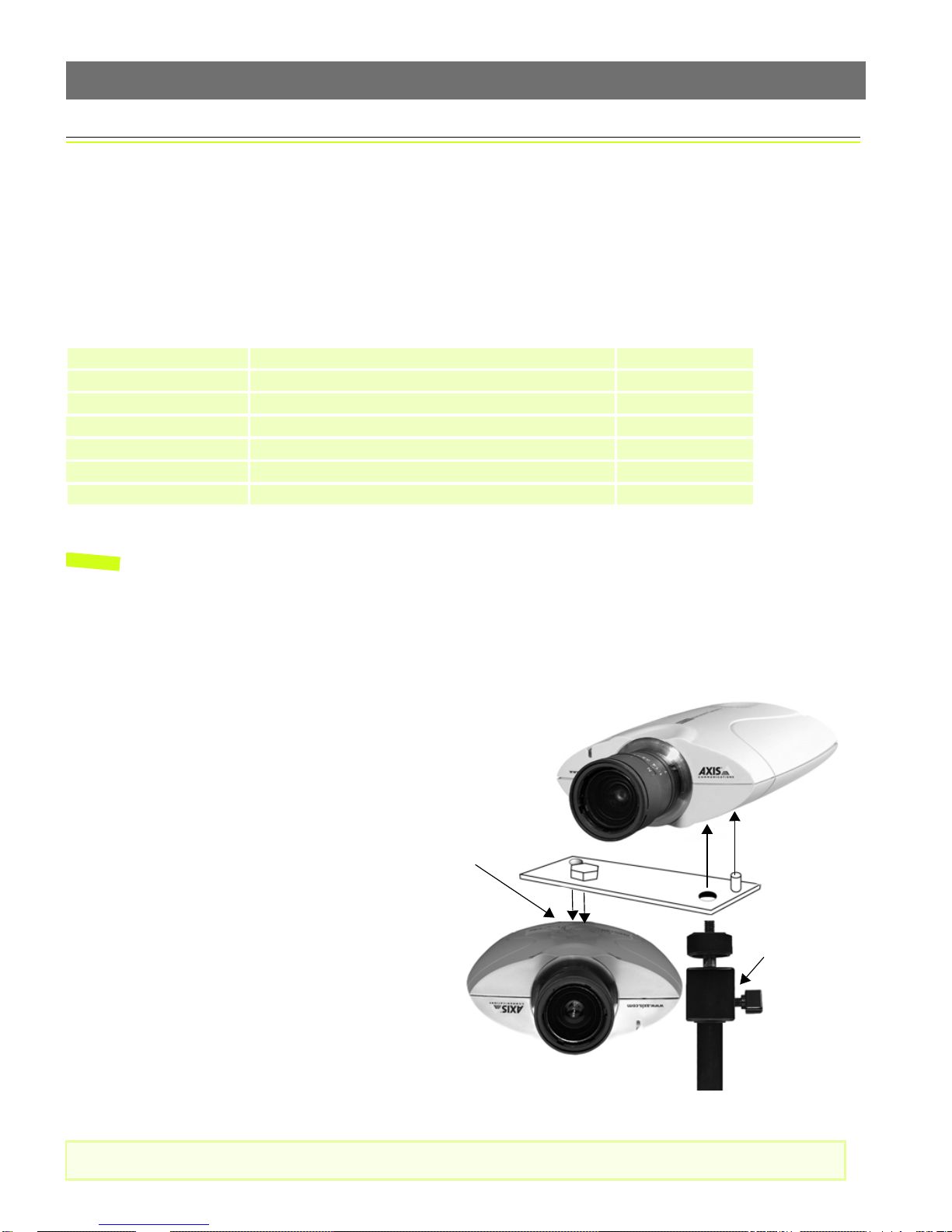
The Mounting Assembly
The mounting assembly consists of a single bracket, used to join the 2 cameras together,
and a single stand, on which the bracket and the 2 cameras are mounted. See below.
The cameras are mounted as shown here,
one the right way up and the other
upside-down. The underside of each
camera has one screw hole and one
guide hole, so that the bracket can only
be fitted in the correct position.
Although the screw holes in the base of
the stand allow the unit to be fastened to
a wall or ceiling, the cameras must still
be horizontal. This can be achieved by
adjusting the ball and socket joint on the
stand by up to 90
o
.
Screw hole and
guide hole.
Ball and socket
joint.
Important!
Please read the important information about outdoor use, on page 19.
Page 10

10
Network Installation AXIS Panorama PTZ User’s Manual
Network Installation
The AXIS Panorama PTZ Network Camera includes 2 cameras. The installation p rocedur e descr ibed
below should be followed for each camera. 2 IP addresses are required.
❶ Note the Serial number on the underside of the unit. You need to know this to set the IP address.
Serial number same as
MAC/Ethernet number; e.g.
00408c100086 =
00-40-8c-10-00-86
❷ Assign your product with a unique IP address (do not use the example address) from a computer
on your network, as follows:
Start a Command Prompt and type these commands:
Syntax:
arp -s <Camera IP address> <MAC address> <my PC IP address>
ping -t <Camera IP address>
Example:
arp -s 172.21.1.200 00-40-8c-10-00-86 172.21.1.193
ping -t 172.21.1.200
Notes: •In Windows you can find out the IP address of your workstation by running winipcfg (Win
95/98/ME) or
•Server Privileges: Although no special privileges are required for Windows 95/98/XP-Home, you
do need Administrator privileges for Windows NT/2000/XP-Professional.
ipconfig (Win NT/2000/XP) from a command prompt.
You will now see ‘Request timed out ...’ messages repeatedly returned in the window.
❸Connect an Ethernet cable to your AXIS
Network socket
RJ-45 connector
❺Approximately 10-15 seconds after connecting power, the message
‘Reply from 172.21.1.200...’ - or similar, is returned in the Command
Prompt window. Ensure that the Power Indicator is permanently lit and
that the Network Indicator flashes intermittently.
Panorama PTZ and attach it to the network.
❹Connect the power adapter to the unit and
connect it to your main power supply.
Power Supply
socket
❻Exit Ping. The installation is now complete, and you are ready
to access the AXIS Panorama PTZ from your browser, as
described in the next section.
Network
Indicator
Power
Indicator
Page 11

AXIS Panorama PTZ User’s Manual Network Installation
Verifying and Completing the Installation From Your Browser
To access the AXIS Panorama PTZ, start your browser and enter the IP address of either camera in
the location or address field, e.g. 171.21.1.200.
This opens the Live View page, which is the default application page. The page provides a link to
the product’s Administration Tools, providing access to all of the camera’s sett ings, including those
for the Panorama application, which must be configured correctly before use. Please see
Configuration, on page 12.
11
The Administration Tools provide
access to the Panorama settings,
and all other available settings.
To quickly find information and help when using the camera, please refer to the Online help,
available from the administration tool pages.
Important!
• To enable the Panorama application, you must set Microsoft Internet Explorer to allow ActiveX controls and install the Axis Panorama Viewer ActiveX component onto your computer. The application
will not function without this component.
• When accessing the Admin Tools for the first time in a browser, you will not be prompted for a username or password. You will be assumed to be the Administrator and will automatically be logged on
as such, with the user name root
be changed as soon as possible, to enable the security function. Also, all Axis products are shipped
with the same password as default. For more information, refer to System Security, on page 17.
and the default password pass. This root password should, however,
Page 12

12
Configuration AXIS Panorama PTZ User’s Manual
Configuration
Having installed your AXIS Panorama PTZ and confirmed that it is accessible on the
network, it is now ready for further configuration. Please note that both
installed and configured.
This section provides information on the minimum configuration necessary for the AXIS
Panorama PTZ, help on configuring the Panorama application, as well as a general
overview of the Web-based Administration Tools.
Minimum Configuration
The minimum configuration required for the AXIS Panorama PTZ should contain the
following points:
• Configured TCP/IP network settings, allowing the product to communicate on the network
• The password for the default user Admin should be changed, to enable the security
function
cameras must be
• Users should be defined and added, thus providing these with access to the camera
Although not required, you may also wish to configure the following:
• The system date and time.
• Images settings for resolution, brightness, compression, etc. Note that to maintain balance
in the Panorama application, these image settings should be made in each camera.
All of these settings can be configured and/or modified at any time from the
Administration Tools. Please see the product’s Online Help for more information.
Important!
• To access the Administration Tools, the product must first be installed on the network, as described
in Network Installation, on page 10.
• Javascript must be enabled in your Web browser for the AXIS Panorama PTZ Web-based interface to
work.
Page 13

AXIS Panorama PTZ User’s Manual Configuration
Configuring the Panorama Application
After completing the minimum configuration of the AXIS Panorama PTZ’s 2 cameras, click
Panorama in the Administration Tools. Note that the Panorma settings only need to be
made in one of the two cameras.
1. Configure/check the IP addresses for the 2 cameras used by the application. The IP
address for the camera currently being used for the configuration should already be
shown, but the IP address for the other (attached) camera must be entered manually.
2. Select the orientation for each camera, i.e. select which camera will be the right way up
and which will be upside down.
3. Set the maximum frame rate to be used, or leave as Unlimited.
4. Select the required image size. The available options are 320x240 and 640x480. Other
image settings are made in the standard administration tools in each camera. See
Minimum Configuration above.
13
Using the Panorama PTZ Tools
The most common way of changing the Panorama view is to use the Pan, Tilt and Zoom
bars provided in the product’s web page, as shown in the illustration below. The bars can
either be clicked anywhere along their length, whereupon they will go directly to that
position or zoom, or alternatively, the arrow heads at the ends of each bar can be used,
whereupon the position or zoom is changed step-by-step.
Zoom bar
Preset positions list
Tilt bar
Snapshot button
Home button
Pan bar
Page 14

14
Configuration AXIS Panorama PTZ User’s Manual
It is also possible to pan and tilt the view simply by left-clicking with the mouse in the
image, whereupon the image centers on the clicked position. To zoom in or out, either use
the mouse wheel, or right-click in the image and select the operation from the menu that
appears. Selecting Zoom in or Zoom out will change the zoom in steps, whereas selecting
Maximize view will zoom the image all the way out.
To go to an existing Preset position select it from the drop-down list to the left. The view
automatically changes to that position. See the following for information on setting up
preset positions.
To save a JPEG snapshot of the current view, click the button provided. This will open a
dialog asking where the image should be saved. Select the location and click Save.
Setting up Preset Postions
A preset position is a defined and saved configuration that steers the panorama view to a
pre-configured area of interest. Up to 16 preset positions can be configured.
Preset positions are configured in the Administration tools, by clicking Panorama>PTZ
Presets. To set up a new preset, steer the view to the desired position, by clicking in the
image or by using the Pan Tilt and Zoom bars. When at the desired position, enter a
descriptive name in the field for Current Position and then click the Save button.
To set a position as the Home position (that is, the default position that is assumed
whenever the Panorama is viewed), position the view as desired, check the box for Use
current position as Home and finally, click the Save button. Any existing position named
Home will be overwritten.
The Preset position time, configurable from 0.0 to 2.0 seconds, determines how quickly
the view changes when selecting another preset position.
The Click time is similar to the Preset position time above, but describes instead how
quickly the view will change when clicking in the image.
Page 15

AXIS Panorama PTZ User’s Manual Configuration
The Administration Tools
The Web-based Administration Tools are used for configuring and managing your AXIS
Panorama PTZ. These tools are can be used at any time for reviewing and/or refining the
configuration. The tools are accessed from the Live View page, as shown on page 11.
Important!
• When accessing the Administration Tools for the first time during a session, you will be assumed to
be the administrator and will be logged in as such, with the username root
pass
.
• You should change the root password as soon as possible. Until this has been done, the security features in the product be will not
password by default. For further information, refer to System Security, on page 17.
be enabled. Furthermore, all Axis products are shipped with the same
The Administration Tools are presented as links in the margin of the Administration Page.
Simply click the relevant link for the parameters you wish to configure. The entire system
is configured and modifed directly from these tools.
and default password
15
Page 16

16
Configuration AXIS Panorama PTZ User’s Manual
Tools Overview
The table below provides an overview of the Administration Tools:
Settings Tool Description
Image Focus the camera using the Focus Assistant, and define the image attributes for your AXIS Panorama PTZ.
Network Configure TCP/IP and SMTP E-mail settings, and make settings for Notification of change in IP address.
System Set the Date and Time, create and delete Users and passwords, and change the Administrator’s password.
External
Devices
Panorama Configure the Panorama application. See page 13.
Applications Description
Operation Choose to run your AXIS Panorama PTZ in Sequential or Alarm Mode; determine when and how often images are
Layout Determine the Layout for the Web page in which your images will appear. Customize the page to your own design
Support Description
General Displays various useful information about how and where to get help, as well as providing tools for restarting and
Help Starts the product’s on-line help
Set the COM-Port on the AXIS Panorama PTZ to use the AXIS 2191 Audio Module. For further information, please
refer to the AXIS 2110 User’s Manual.
taken using the Scheduler; and define when the images are uploaded to an ISP, or target FTP/Web server. Note
that although these options may be enabled and available, their use is not supported. For further information,
please refer to the AXIS 2110 User’s Manual.
and include your own logos, links and title texts, and enable or disable specific function buttons.
resetting the unit.
Page 17

AXIS Panorama PTZ User’s Manual Configuration
System Security
To prevent unauthorized use, the AXIS Panorama PTZ supports multi-user password
protection and access is restricted to defined users only. The system Administrator(s) has
unrestricted access to the camera’s Administration Tools and can determine the registration
and access rights for all users.
User Access Rights
Click System and then Users to perform any of the following tasks:
• edit the administrator (root) password
• define, add and delete user names and passwords
• assign individual access rights to a selected user, where each user is given one or all of the following levels of access:
•Admin: a user granted Admin rights has unrestricted access to the camera’s Administra-
tion Tools and can consequently determine the registration of all users.
17
•Dial-in: provides the user with dial-in modem access to the AXIS Panorama PTZ.
•View: provides the lowest level of access, which allows the user to view the images only.
Adding at least one such user will disable anonymous users.
Important!
• The Administrator’s default user name and password (set to root and pass) can be used for logging in
to the unit for the first time, but the default passw ord must be changed to enable the camera’s security functions. All Axis products are shipped with the same password as default.
• By default, the AXIS Panorama PTZ is set for anonymous user access, which means that anybody on
the network can view the video images from a browser. To restrict open access, simply register a single authorized user with viewing rights. This effectively disables the anonymous user service and
restricts camera access to specified users. If the anonymous user service is satisfactory for your
application, simply do not add any other users.
Page 18

18
Configuration AXIS Panorama PTZ User’s Manual
Reinstating the Factory Default Settings
In certain circumstances, it may be necessary to reinstate the Factory Default settings for
your AXIS Panorama PTZ. This is performed by clicking the Support link in the
Administration Tools and then selecting Restart/Reset, or by pressing the Control Button.
Follow the instructions below to reinstate the product factory default settings using the
Control button:
1. Switch off the AXIS Panorama PTZ by disconnecting the power cable.
2. Press and keep the Control Button pressed, and then reconnect the power cable.
3. Keep the Control Button pressed until the Status Indicator displays yellow (note that
this may take up to 15 seconds), then release the button. When the Status Indicator
displays green (which can take up to 1 minute) the AXIS Panorama PTZ will then have
been reset to the original factory default settings.
Notes: •Reinstating the original default settings will cause all parameters (including the IP address) to
be reset.
•Refer to Network Installation, on page 10, for information on how to set the camera’s IP
address.
Page 19

AXIS Panorama PTZ User’s Manual Lenses and Focusing
Appendix A - Lenses and Focusing
The AXIS Panorama PTZ can be focused manually, or with the help of the Focus Assistant.
The latter is useful if your AXIS Panorama PTZ is located remotely from your viewing
workstation. Having positioned the camera, follow the instructions below to focus it.
Important!
Although the AXIS Panorama PTZ is intended for both outdoor and indoor use, it is important to note
that the charged coupled device (CCD) in the camera can become permanently damaged if it is exposed
to excessive direct sunlight or halogen light. It is therefore important that the Adjustment Ring is not set
fully open when installing the camera in bright light conditions. The Axis warranty does not cover CCD
damage caused by prolonged exposure to strong light.
Manual Focusing
19
❶Power-on the AXIS Panorama PTZ and wait 10 seconds.
❷The Iris Adjustment Ring effectively closes
and opens the camera lens to regulate the
amount of light entering the camera. Closing
the ring reduces the amount of light to produce a better depth of field and focus over a
greater distance, whereas, a more open lens
provides better results in low-light conditions.
Rotate the Iris Adjustment Ring to an appropriate position for your chosen installation,
as follows:
• indoor scene - fully open (O)
• outdoor scene - mid position
(between C and O)
Iris Adjustment Ring
Focus Ring
Status Indicator
Control Button
Note: The unit is supplied with the lens set in approximate focus position.
❸Start your browser
and check the picture.
❹Rotate the Focus Ring
to an appropriate positon - until you are satisfied with the quality of
the camera image.
Page 20

20
Lenses and Focusing AXIS Panorama PTZ User’s Manual
Focusing using the Focus Assistant
The Status Indicator, used in conjunc tion with the Focus Assistant, provides an immediate
visual display that will help you achieve a good basic level of focus at the point of
installation.
Focus Quality
Once set to Focus Mode, the Status Indicator displays the following colors, which
represent predefined levels of focus:
Color Level of Focus (%) Focus Quality
Red 0 - 60 Poor
Yellow 60 - 80 Reasonable
Green 80 - 100 Good
Rotational Focus Control
The lens provided with the AXIS Panorama PTZ has rotational focus control that allows
the focal length of the lens to be adjusted manually. The lens is used to establish the basic
level of focus when the image is stable, that is, when there is little or no movement. Rotate
the lens clockwise for close focus, or anti-clockwise for distant focus.
You will probably find that the Status Indicator displays green, indicating a good level of
focus, several times during the full traverse of the lens assembly. This is because several
planes of focus exist within the camera's normal field of view.
Focusing the Camera Under Stable Conditions
Before you begin:
For the focusing algorithm to work effectively, always ensure that there is minimal movement within the
camera’s field of view when focusing, as described below.
With reference to the illustrations, follow the instructions below to achieve a good basic
level of focus under normal stable conditions:
Important!
Do not press the Control Button for at least 10 seconds after powering on the unit - as this will cause
the product to return to the factory default settings.
Page 21

AXIS Panorama PTZ User’s Manual Lenses and Focusing
21
1. Set the Focus Ring to its extreme far-focus
Status Indicator
position by turning it fully anti-clockwise.
2. Rotate the Iris Adjustment Ring to an
appropriate position for your installation, as
follows:
• indoor scene - fully open (O)
• outdoor scene - mid position (between C
Control Button
and O)
3. Press and hold the Control Button using a
paper clip, or any other pointed object (see
illustration) - until the Status Indicator
flashes Yellow. This enables the Focus
Assistant, sets the Status Indicator to Focus
Mode, and simultaneously starts a focusing algorithm that regularly calculates the
quality of focus within the camera's field of view.
4. Turn the Focus Ring slowly clockwise until the Status Indicator displays Green; that is,
until a Good level of focus is achieved. The Status Indicator displays different colors to
represent a predefined level of focus (see table below).
5. Return to your browser application and review the picture quality . Repeat step 5 only
if
you consider the focal distance as too distant - until you are satisfied with both the
focal distance and focus quality.
6. To exit the Focus Assistant: press and hold the Control button until the Status
Indicator flashes Yellow. The Status Indicator displays Green after releasing the button.
Notes: •The Focus assistant can also be enabled and disabled from the Image-Focus page.
•A Good level of focus is normally attainable throughout several planes within the camera’s
focusing spectrum.
•The Status Indicator displays Green to indicate a Good level of focus at 80% of optimum focus.
•Since optimum focusing is dependent on the camera’s field of view, it is important to scan the
focusing plane from the closest to furthest perspectives before attempting any fine-tuning.
Replacing the Lens
The lenses supplied with the AXIS Panorama PTZ are intended specifically for use with the
Panorama application. Other compatible lenses may also be used with the cameras, but
there is no guarantee that the Panorama application will function correctly. For more
information on replacing lenses, please see the AXIS 2110 User’s Manual.
Page 22

22
Troubleshooting AXIS Panorama PTZ User’s Manual
Appendix B - Troubleshooting
This appendix provides useful information on solving problems you might have with your
AXIS Panorama PTZ.
Pinging Your IP Address
By sending a packet to the specified address and waiting for a reply, the Ping utility can
determine whether a specific IP-address is accessible. It also provides a useful method for
confirming addressing conflicts on the network.
Follow the instructions below in association with Problems, Possible Causes and Remedial
Actions, on page 23, and run the Ping utility to troubleshoot TCP/IP problems on your
network:
1. Start a Command window and type
ping x.x.x.x, where x.x.x.x is the IP address of
the AXIS Panorama PTZ.
2. If you receive the reply
destination host unreachable, then the AXIS Panorama
PTZ is not accessible on your subnet. You must obtain a new IP address and reinstall
the unit.
If this does not solve the problem, disconnect
the AXIS Panorama PTZ from the network
and run Ping again. See the table below for an interpretation of the results.
Ping Reply Interpretation and recommendation
Reply from <IP address>: bytes = 32; time = 10
ms.....
Request timed out This IP address is not used and is available for use with your AXIS
The IP address is already in use and cannot be used again. You must obtain
a new IP address.
Panorama PTZ. If you already installed the unit using this IP address, the
installation may have failed. Reinstall the unit. Also check all cabling.
Page 23

AXIS Panorama PTZ User’s Manual Troubleshooting
Problems, Possible Causes and Remedial Actions
Symptoms Possible causes Remedial actions
The AXIS Panorama PTZ
cannot be accessed from a
browser.
The Power indicator is not
constantly lit.
The Network indicator
displays red.
The IP address is already in
use by another device.
The IP address is located on a
different subnet.
In Windows 95, the ARP
table was empty when you
tried to set the IP address.
Possible probl e m with your
proxy server.
Other networking problems. Try replacing your network cable.
Faulty power supply. Verify that you are using an AXIS PS-D power supply.
Faulty cabling. To verify that the cables are functional, Ping the address of a
Disconnect your AXIS Panorama PTZ from the network.
Run the Ping utility (as described in Pinging Your IP Address, on
page 22) and follow the appropriate recommendations.
Note: The assigned IP number can be assumed valid if Ping returns
“request timed out” - in which case you should set the IP address
again, power on the AXIS Panorama PTZ and then try accessi ng it
again.
Run the Ping utility (as described inPinging Your IP Address, on page
22). If Ping returns “Destination host unreachable” or similar, the
diagnosis is probably correct.
In Windows, check that the IP address for your AXIS Panorama PTZ
is on the same subnet as your workstation. Exactly how this is done
varies from one version of Windows to another. See Windows’ help
for more information.
If your AXIS Panorama PTZ and your workstation are on different
subnets, you will not be able to set the IP address. Contact your
network administrator.
If the table is empty, re-install the product ensuring that the IP
address for your own PC is also used. Type
ARP table.
Note: The AXIS IP Installer provides a good alternative to ARP.
Try disabling the proxy default in your browser.
Test the network interface of the product by connecting a local
computer to the unit, using a standard Crossover (hub-to-hub)
Cable.
If the above actions don’t solve the problem, the AXIS Panorama
PTZ may be faulty. In this case, try to localize the problem by
connecting the AXIS Panorama PTZ to the serial port of a local
computer, using a Null Modem Cable; and report your findings to
your local reseller.
known unit on your network.
If the cabling is OK and your network is reachable, you should
receive a reply similar to this:
Reply from x.x.x.x: bytes = 32 time = 2 ms,
arp -a to view the
23
The Active and Network
indicators flash every 0.5
seconds.
The AXIS Panorama PTZ
works locally, but not
externally.
Hardware failure. Contact your Axis reseller.
Firewall protection Check the Internet firewall with your system administrator.
Default routers required Check if you need to configure the default router setti ngs.
The Internet sit e is too
heavily loaded.
Configure the AXIS Panorama PTZ to upload your video images to
an FTP server or an ISP.
Page 24

24
Troubleshooting AXIS Panorama PTZ User’s Manual
Symptoms Possible causes Remedial actions
The Panorama application
displays an incomplete image
and the text "No image
available."
The two images in the
Panorama application are
not joined satisfactorily.
No image using Refresh
and/or slow updating of
images.
A series of broad vertical
white lines appears across
the image.
Bad focus. Focus has not been correctly
Noisy images. Images may be noisy if you
Poor quality images. The display properties are
No images available in your
browser application.
The second camera has not
been correctly configured.
Incorrect mounting on
bracket.
Requests for images of
varying size and resolution
place a greater demand on
the available file space
within the AXIS Panorama
PTZ.
The CCD sensor becomes
overloaded when the light is
too bright. This can happen
e.g. with sunlight reflexes.
adjusted.
No adaptor fitted with your
C-type lens.
are using the AXIS Panorama
PTZ in a very low light
environment.
incorrectly configured for
your desktop.
ActiveX disabled. In Microsoft Internet Explorer, ensure that ActiveX has not been
Configure the second camera, using the Administration tools.
Check that both cameras are securely fastened on the bracket.
Ensure that all the clients accessing the images are u sing the same
image resolution and compression.
Although the AXIS Panorama PTZ can be used outdoors, exposure
to extreme sunlight or halogen light may still cause serious damage
to the CCD sensor. Reposition your AXIS Panorama PTZ in a more
shaded location immediately.
Note: damage caused to the AXIS Panorama PTZ through
overexposure to direct sunlight or halogen light is not covered
under the product warranty.
Referring to the on-line help, adjust the White Balance setting and
then try resetting the camera focus again using the Focus
Assistant, as described in Lenses and Focusing, on page 19.
If you have previously replaced the supplied CS-type lens, you may
have inadvertently installed a C-type lens witho ut first fitting the
required adaptor. See also page 21.
To solve this problem, you need more light. The performance of the
camera is best in the range 100 - 3.000 lux.
Open the Display Properties in your desktop and configure your
display to show at least 65 000 colors, i.e. at least 16-bit.
Note: Using only 16 or 256 colors on your computer will produce
dithering artifacts in the image.
disabled in the Internet Options m enu.
Notes: •If using a DHCP server to set the IP addresses for the two cameras, please ensure that these
addresses are configured as static and not dynamic, otherwise the Panorama application will
need to be reconfigured each time the IP address changes.
•If you still have a problem after reading this information, please contact your reseller, or visit
the Axis Support Web at www.axis.com/techsup/
Page 25

AXIS Panorama PTZ User’s Manual Other IP Setup Methods
Appendix C - Other IP Setup Methods
In addition to the ARP command (described in the Installation section), you can
alternatively set the IP address for your AXIS Panorama PTZ using the following methods:
Method Operating Systems Notes
25
AXIS IP Installer Windows 95/98/ME and
NT/2000
DHCP
This method should only be used if you know which
IP address the DHCP server will give the camera, or
if your version of DHCP can update a DNS server,
which then allows you to access the camera using
a name.
Most Wh en using a DH CP server to set th e IP
See Using the AXIS IP Installer, on page 26.
addresses for the two cameras, ensure that
these addresses are configured as static and
not dynamic, otherwise the Panorama application will need to be reconfigured each time
the IP address changes.
Notes: •Do not use the default or IP address featured in these examples when installing your AXIS Pan-
orama PTZ. If in doubt, consult your network administrator to obtain an unused IP address.
•Make sure the AXIS Panorama PTZ is powered up and attached to the network.
•Server Privileges: Although no special privileges are required for Windows 95/98, you do need
Administrator privileges for Windows NT/2000.
MAC/Ethernet Address: The AXIS Panorama PTZ is pre-configured with a unique MAC/Ethernet address
based upon the serial number printed on the underside label of the unit; where the serial number typically
follows the format 00-40-8c-xx-yy-zz. You must know the MAC/Ethernet address to complete the
installation.
Page 26

26
Other IP Setup Methods AXIS Panorama PTZ User’s Manual
Using the AXIS IP Installer
AXIS IP Installer is a Windows program that is ideal for setting the IP addresses for
multiple Axis networking products on your network. Also allowing you to access the home
Web page of any Axis ThinServer device connected to your network, this freely distributed
software is available for download from www.axis.com.
Installing the AXIS IP Installer:
1. Download the latest AXIS IP Installer software to your workstation and run the
Setup_IPInstaller.exe program to start the installation.
2. The AXIS IP Installer - Setup dialog is displayed on the screen.
3. Follow the instructions as they appear on the screen.
4. Click Finish to complete the installation.
Setting the IP Address with the AXIS IP Installer:
1. Run the AXIS IP Installer from the Start menu. The following window will appear:
2. Restart your AXIS Panorama PTZ.
3. Select the serial number of your AXIS Panorama PTZ in the list. The serial number is
identical to the unit’s MAC/Ethernet address.
4. Enter the IP address. Click Set IP address. The IP address will now be set.
5. To access the home page of the AXIS Panorama PTZ, click Home page of selected
Axis-server... You can now configure the AXIS Panorama PTZ according to your
requirements.
6. Click OK to exit the program.
For more help during the installation of the IP address, click Help or press the F1 key.
Page 27

AXIS Panorama PTZ User’s Manual Upgrading the Firmware
Appendix D - Upgrading the Firmware
The AXIS Panorama PTZ camera firmware is stored in flash memory. This memory is
provided by a silicon chip that, just like any other ROM device, retains data content even
after power is removed. Flash memory is unique because it allows its data to be erased and
re-written. This means you can install firmware upgrades for your AXIS Panorama PTZ as
they become available - without having to replace any parts. New firmware can simply be
loaded into the AXIS Panorama PTZ over the network.
Obtaining Upgraded firmware
The latest version of the AXIS Panorama PTZ firmware is available free of charge from the
Axis Website at www.axis.com, or from your local distributor.
Upgrading the firmware
The AXIS Panorama PTZ firmware is upgraded over the network using FTP. See the
detailed instructions supplied with each new release.
27
Important!
• Always read the instructions provided with each new release, prior to upgrading your firmware.
• Upgrading normally takes between 30 seconds and 10 minutes, although it can take longer. After
starting the process, you should always
orama PTZ - even if you suspect the upgrade procedure has failed.
• In controlled environments, flash memory upgrades provide a very safe method for upgrading firmware. However, flash products can become damaged if the upgrade operation is not performed correctly. Your dealer reserves the right to charge for any repair attributable to faulty upgrading by the
user.
wait at least 20 minutes before power-cycling the AXIS Pan-
Page 28

28
Technical Specifications AXIS Panorama PTZ User’s Manual
Appendix E - Technical Specifications
System Requirements - TCP/IP support on Windows 95, 98, NT, 2000 or XP. Microsoft
Internet Explorer 4.x, or higher (to use the Axis ActiveX component AXIS Camera Control)
Network Connection - RJ45 twisted pair cable, or remote connection using any standard
serial modem.
Networking - 10baseT Ethernet or 100baseTX Fast Ethernet, TCP/IP, HTTP, FTP, SMTP,
NTP, ARP and BOOTP.
I/O Connector - 1 optical-isolated alarm input. 1 digital output (max 24 V, 100 mA) with
programmable digital input/output for remote image storage via FTP or SMTP, pre/post
alarm image storage.
Pan/Tilt/Zoom - Pan: up to 140
Image Updating - Up to 15 frames/second on 10/100 Mbit networks.
Pre/Post Alarm Buffer - Up to 500 KB memory available for pre/post alarm image storage.
Modem Connector - Single 9-pin D-SUB RS-232 connector, max 115 Kbit/s, half duplex
Operating Conditions: - Temp: 40
Approvals - EMC: FCC Class A, EN 55022/1994, EN55024/1998
o
. Tilt: up to 65o. Zoom; from 0.24x to 4x.
o
to 105o F (+5o to +40o C), Humidity: 20-80% RHG.
Safety: EN 60950, UL, CSA.
Metrics (per camera): - Height: 1.6” (4.1 cm), Width: 4.1” (10.5 cm), Length: 6.9” (17.5 cm),
Weight: 0.56 lb. (0.26 kg) excluding power supply.
Hardware - ARTPEC-1 compression chip; ETRAX-100, including, 32-bit RISC, 100 MIPS
CPU, 8 MB RAM, 2 MB FLASH PROM.
Power - External power supply 12 V AC, 9.6 VA (PS-D, included), 9-15 V AC, min. 10 VA,
or 9-15 V DC, min. 7 W.
Page 29

AXIS Panorama PTZ User’s Guide Index
L
Index
Linux 6
Live View page 11
A
Access rights 17
Administrator password 17
Anonymous user access 17
ARP 23
ARTPEC-1 28
AXIS IP Installer 25
M
Manual focusing 19
N
Network connector 8
Network indicator 8, 23
Network installation 10
C
Compression 6
Configuration 12
Configure Panorama 13
Configure preset postions 14
O
Obtaining upgraded firmware 27
Other IP setup methods 25
29
D
DHCP server 24
E
Ethernet 5
Ethernet address 25
ETRAX-100 28
F
Factory Default Settings 18
Fast Ethernet 5
Firmware 27
Focus Assistant 20
Focusing 19
I
I/O connector 8
Installation 10
IP address 10
IP setup methods 25
J
JPEG image format 5
P
Panorama 13
Password protection 17
Pinging Your IP Address 22
Power indicator 23
Power supply connector 8
Preset positions 14
Proxy server 23
PTZ tools 13
R
Reset 18
RS-232 connector 8
S
Security 17
Serial number 7
Status Indicator 20
T
Technical specifications 28
Troubleshooting 22
U
Upgrading the firmware 27
Users and passwords 17
Page 30

30
Glossary of Terms AXIS Panorama PTZ User’s Guide
Glossary of Terms
photographs. Also known as JPG.
ActiveX - A control (or set of rules) used by a browser.
ActiveX controls are often downloaded and installed
automatically as required.
ARP - Address Resolution Protocol. A protocol for
assigning an IP address to a physical device address that is
recognized in the local network. The ARP command can be
used to set the IP-address for your product.
ARTPEC - Axis Real Time Picture Enc oder - used for image
compression.
BOOTP - A protocol that can automatically configure a
network device (give it an IP address).
Bps - Bits per second. A unit for measuring speeds in
networks. A LAN might run at 10Mbps or 100Mbps.
CCD - Charged Coupled Device. This is the camera
component that converts the image to digital signals.
CGI - Common Gateway Interface. A set of rules (or a
program) that allows a Web Server to communicate with
other programs.
CS-Mount/C-Mount - Industry standards defining types of
lens fittings. The CS-Mount positions the lens approx. 5mm
further from the CCD than the C-Mount does.
DSL - Digital Subscriber Line. A means of transferring data
via standard phone lines.
Ethernet - A widely used networking standard.
ETRAX - Axis' own microprocessor.
Firewall - A virtual barrier between a LAN (Local Area
Network) and other networks, e.g. the Internet.
Frame Grabber card - Plug-in hardware for "grabbing"
images
FTP - File Transfer Protocol. Used for simple transfer of
files to and from an ftp-server.
HTML - Hypertext Mark-up Language. Used widely for
authoring documents viewed in web browsers.
HTTP - Hypertext Transfer Protocol. The set of rules for
exchanging files (text, images, sound, video, and other
files) on the World Wide Web.
Intranet - A private network limited to an organisation or
corporation. Usually closed to external traffic.
IP - Internet-Protocol. See TCP/IP.
LAN - A local area network (LAN) is a group of computers and
associated devices that typically share common resources within
a limited geographical area.
Linux - A popular operating system, that is “open source” and
practiclly free of charge.
Lux - A standard unit for light measurement.
NWAY - A network protocol that automatically negotiates the
highest possible common transmission speed between two
devices.
Null Modem Cable - A cable used for conne cting a PC to a serial
device, using the modem protocol for communication.
Ping - A small utility used for sending data packets to network
resources to check that they are working and that the network is
intact.
PPP - Point-to-Point Protocol. A method allowing one computer
to connect to another, usually via a modem over a phone line.
Pre/post alarm image - The images from immediately before and
after an alarm.
Protocol - A special set of rules governing how two entities will
communicate. Protocols are found at many levels of
communication, and there are hardware protocols and software
protocols.
SMTP - A common e-mail protocol.
TCP/IP - Transmission Control Protocol/Internet Protocol. A suite
of network protocols that determine how data is transmitted.
TCP/IP is used on many networks, including the Internet. TCP
keeps track of the individual packets of information and and IP
contains the rules for how the packets are actually sent and
received.
URL - Uniform Resource Locator. An "address" on the network.
V.90 - An operating standard for telephone modems.
WAN - Wide-Area-Network. Similar to a LAN, but on a larger
geographical scale.
Web server - A program on a computer that delivers the
resources (usually web pages) requested by the web user (the
client).
Wizard - A program designed specifically to guide the user
through a procedure. Typically used for installations and
configurations.
IP number (address) - A unique number used by a computer
on the network to allow it to be identified and found.
JPEG - A standard image format, used widely for
AXIS COMMUNICATIONS
<Product Name> Quick User’s Guide
 Loading...