

Page 1

INSTALLATION GUIDE
Drop Ceiling Mount
for
AXIS P33 Network Camera Series
ENGLISH DEUTSCH
FRAN
Ç
AIS
ITALIANO
ESPAÑOL
Page 2
About this Document
This document includes instructions for installing the
Drop Ceiling Mount for the AXIS P33 Network Camera
Series. For information about compatible products, go to
www.axis.com
Equipment Modifications
This equipment must be installed and used in strict
accordance with the instructions given in the user
documentation.
Liability
Every care has been taken in the preparation of this
document. Please inform your local Axis office of any
inaccuracies or omissions. Axis Communications AB
cannot be held responsible for any technical or
typographical errors and reserves the right to make
changes to the product and documentation without
prior notice. Axis Communications AB makes no
warranty of any kind with regard to the material
contained within this document, including, but not
limited to, the implied warranties of merchantability
and fitness for a particular purpose. Axis
Communications AB shall not be liable nor responsible
for incidental or consequential damages in connection
with the furnishing, performance or use of this material.
This product is only to be used for its intended purpose.
RoHS
This product complies with both the European
RoHS directive, 2002/95/EC, and the Chinese
RoHS regulations, ACPEIP.
Disposal and Recycling
When this product has reached the end of its useful life,
dispose of it according to local raws and regulations. For
information about your nearest designated collection
point, contact your local authority responsible for waste
disposal.
In accordance with local legislation, penalties may be
applicable for incorrect disposal of this waste.
Europe
This symbol means that the product shall not
be
disposed of together with household or
commercial waste.
Directive 2012/19/EU on waste electrical and electronic
equipment (WEEE) is applicable in the European Union
member states. To prevent potential harm to human
health and the environment, the product must be
disposed of in
an approved and environmentally safe recycling process.
For information about your nearest designated
collection point, contact your local authority responsible
for waste
disposal. Businesses should contact the product supplier
for information about how to dispose of this product
correctly.
This product complies with the requirements of Directive
2011/65/EU on the restriction of the use of certain
hazardous substances in electrical and electronic
equipment (RoHS).
Support
Should you require any technical assistance, please
contact your Axis reseller. If your questions cannot be
answered immediately, your reseller will forward your
queries through the appropriate channels to ensure a
rapid response. If you are connected to the Internet, you
can:
• download user documentation and software updates
• find answers to resolved problems in the FAQ database.
Search by product, category, or phrase
• Report problems to Axis support staff by logging in to
your private support area
• chat with Axis support staff (selected countries only)
visit Axis Support at www.axis.com/techsup/
Contact Information
Axis Communications AB
Emdalavägen 14
223 69 Lund
Sweden
Tel: +46 46 272 18 00
Fax: +46 46 13 61 30
www.axis.com
Page 3
Drop Ceiling Mount Installation Guide Page 3
Important!
This product must be used in
compliance with local laws and
regulations.
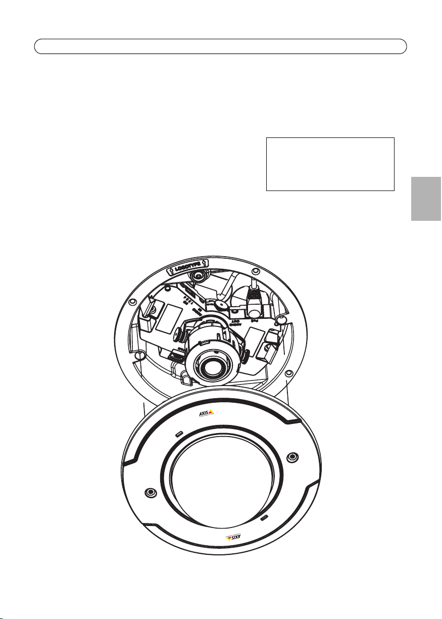
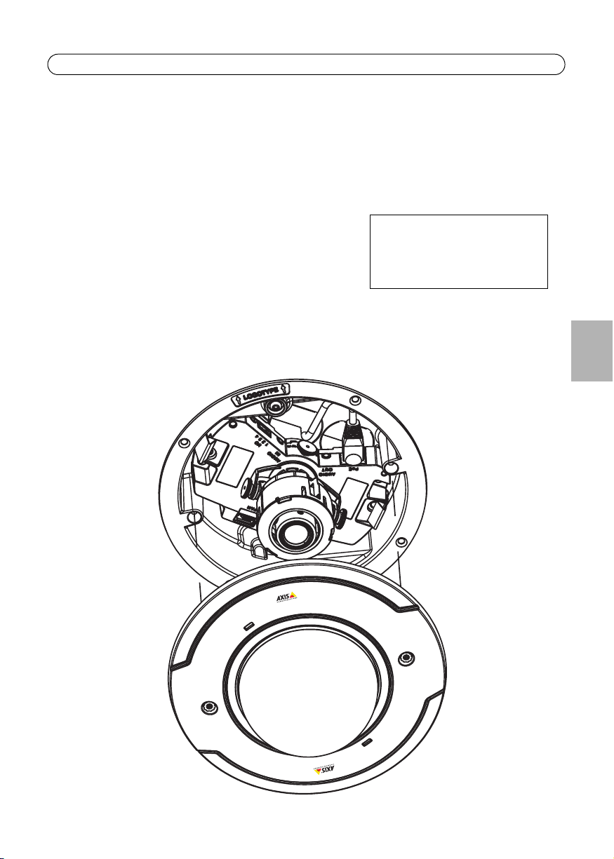
Drop Ceiling Mount Installation Guide
This installation guide provides instructions for installing the drop ceiling mount for the AXIS P33
Network Camera Series. Please read through the entire guide before proceeding with the
installation.
For all other aspects of using the Axis network camera,
please see the Installation Guide and User’s Manual,
available from www.axis.com/techsup
Installation steps
• Check the package contents against
the list on page 4.
• Installation instructions. See page 6.
ENGLISH
Page 4
Page 4 Drop Ceiling Mount Installation Guide
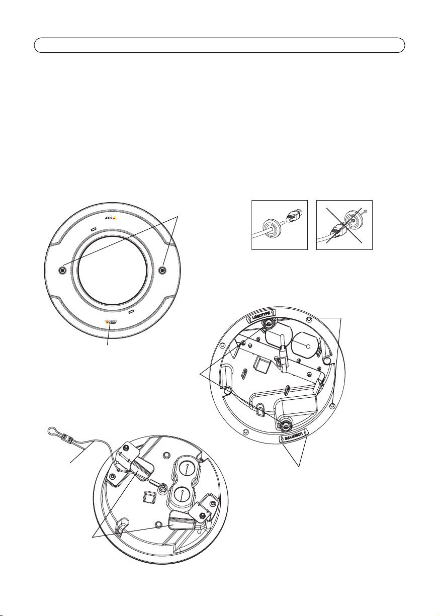
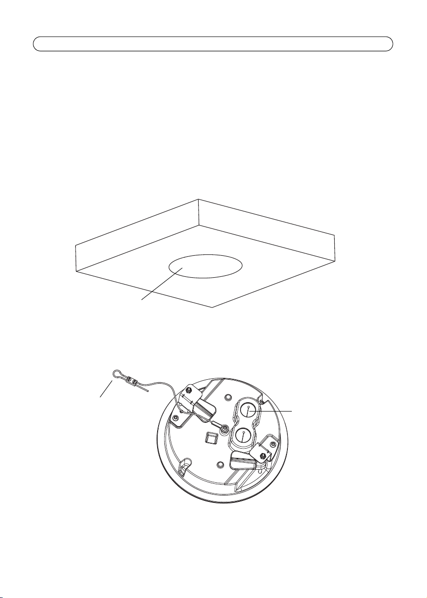
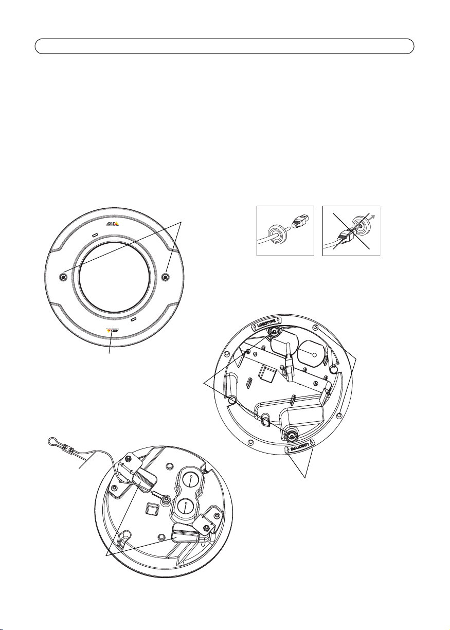
Ceiling bracket
(bottom)
Logotype arrow points to where the
logo will appear when the installation
is complete
Plastic dome cover
Captive
screws
Logotype
Safety wire
Ceiling bracket
(top)
Support arms
Support arm
screws
Alternate
screw holes
(4x)
Rubber cable gasket (cable not included)
Package contents
• 1 Plastic dome cover
• 1 Ceiling bracket
• 1 Safety wire & M4x6 screw
• 2 Rubber gaskets
• 1 Hole template
• 1 Drop Ceiling Mount Installation Guide (this document)
Page 5
Drop Ceiling Mount Installation Guide Page 5
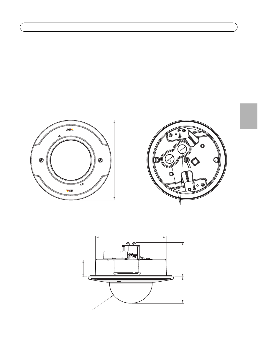
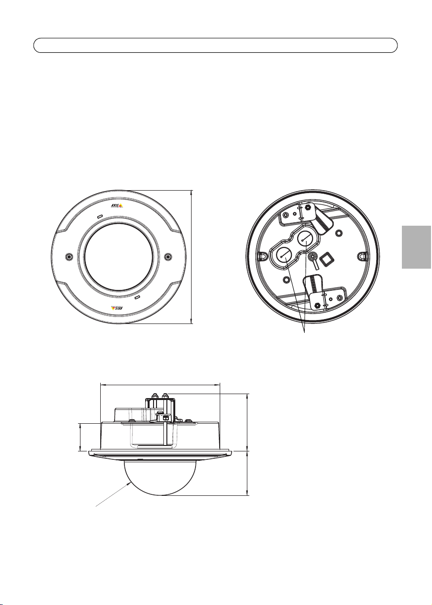
Ceiling bracket (top)
Plastic dome cover
Cable holes for gaskets
Ceiling bracket
(side view)
Ø21mm/0.8”
Ø191mm/7.5”
159.3 mm/6.27”
85 mm/3.2”
63 mm/2.5”
10-60 mm/
0.4-2.4”
48 mm/1.9”
Specifications
• Total weight (camera plus ceiling mount): 0.9kg (2.0 lb)
• Plastic dome cover diameter: 191 mm (7.5”)
• Ceiling hole (ceiling bracket top) diameter: 159.3 mm (6.27”)
• Cable hole for gasket (2 holes) diameter: 21 mm (0.8“)
• Ceiling thickness: 10-60 mm (0.4” - 2.4”), if using the support arms to secure the drop ceiling mount into place
ENGLISH
Note:
The IP51-rating of the installation using support arms and rubber cable gaskets applies to
the installation above the ceiling tile only.
Page 6
Page 6 Drop Ceiling Mount Installation Guide
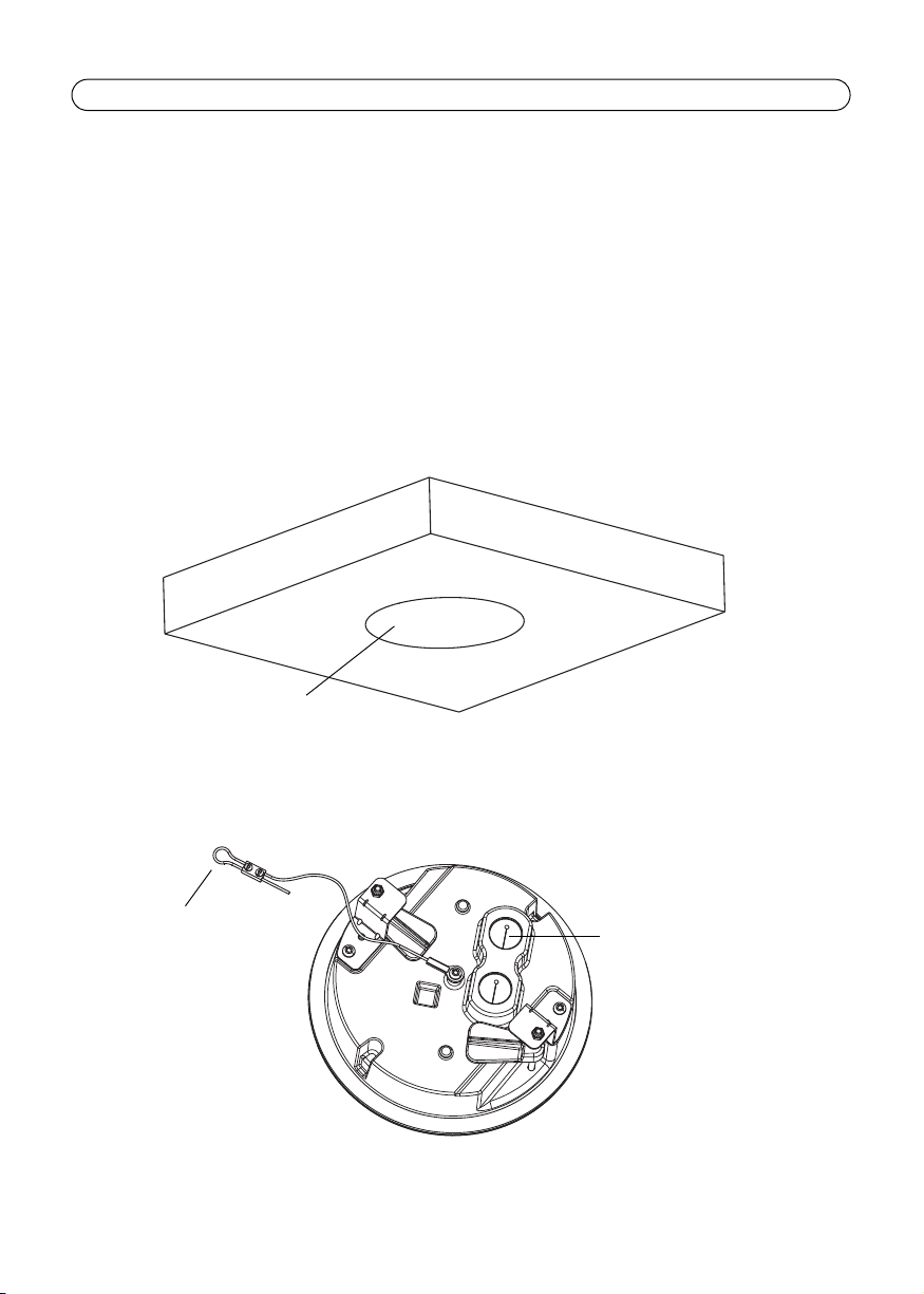
Ceiling tile
Hole diameter 159.3mm/6.27”
Attach to ceiling
Cable hole with
black foam gasket
Install the Drop Ceiling Mount
1. If possible, remove the ceiling tile in which the drop ceiling mount is to be fitted.
2. Use the supplied template to mark the position for the 159.3 mm (6.27”) hole in the ceiling tile.
Remove the protective paper, fix to ceiling tile and cut around the template.
Notes:
• The combined weight of the camera and ceiling mount is 0.9 kg (2.0 lb). Check that the ceiling
material is strong enough to support this weight.
• The thickness of the ceiling tile should be 10-60 mm (0.4” - 2.4”).
• Make sure the surface is flat so the bracket will fit securely all round.
3. To secure the camera using the supplied safety wire, replace the ceiling tile and attach the end
of the safety wire to a suitable point in the ceiling, above the drop ceiling.
4. Route the network cable through the ceiling hole.
5. Remove the black foam gaskets from the cable holes in the bracket.
Page 7
Drop Ceiling Mount Installation Guide Page 7
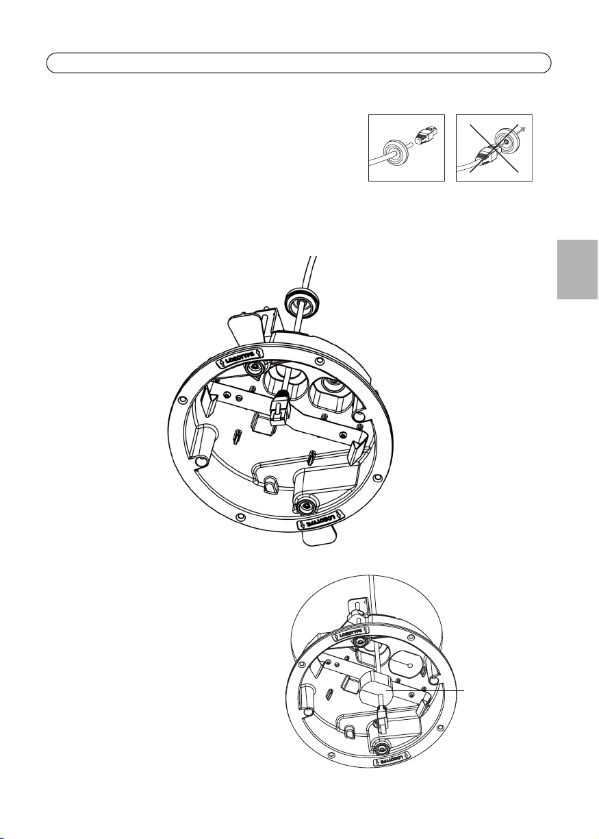
Network cable and rubber gasket
Foam gasket
6. For an IP51-rated installation, prepare the network
cable with a rubber gasket (supplied):
Gently force the cable through the rubber gasket and
attach a network connector.
7. Plug both cable holes with the supplied rubber gaskets.
Notes:
• If necessary, pierce a hole in the gasket with the resitorx screwdriver, do not use a knife or other
sharp object.
• Do not force the network connector through the gasket
ENGLISH
Alternatively, fit the black foam gasket
around the network cable, and place the
foam gasket with the network cable into the
cable hole.
Note:
The installation with the black foam gasket is not IP51-rated.
Page 8
Page 8 Drop Ceiling Mount Installation Guide
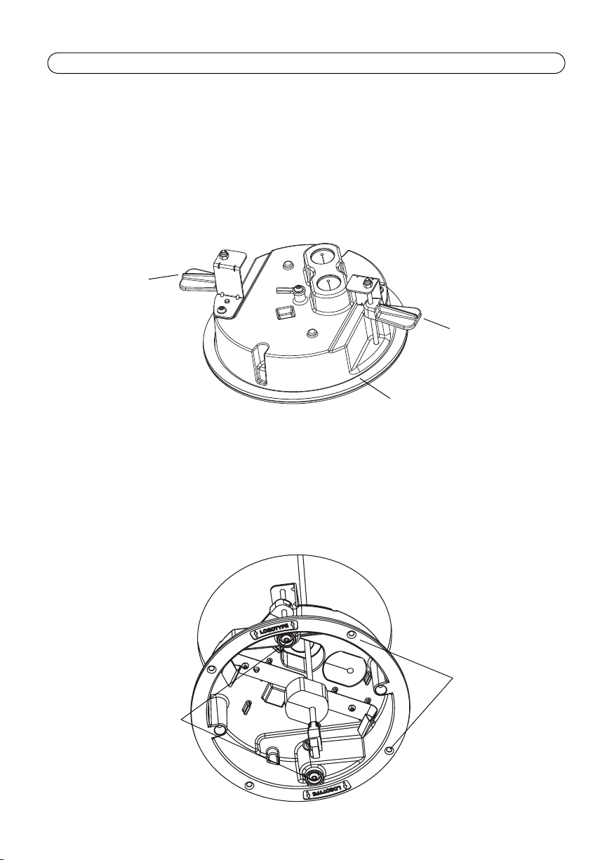
Support arm
Support arm
Black rubber rim
Support arm screws
Alternate screw
holes (4x)
Complete the installation
1. Put the ceiling bracket up into the ceiling, and position the logotype labels where you want the
logotypes on the plastic cover.
2. Tighten the support arm screws using a torx 20 screwdriver. The arms will fold out over the
ceiling and lock into place. Make sure that screws are securely and evenly tightened so the
black rubber rim is completely attached to the ceiling tile.
Alternatively, secure the ceiling bracket using the four alternate screw holes (this method is not
IP51-rated).
Note:
• If you secure the drop ceiling mount with the alternate screw holes, use flat head screws which will
not obstruct the plastic dome cover.
Page 9
Drop Ceiling Mount Installation Guide Page 9
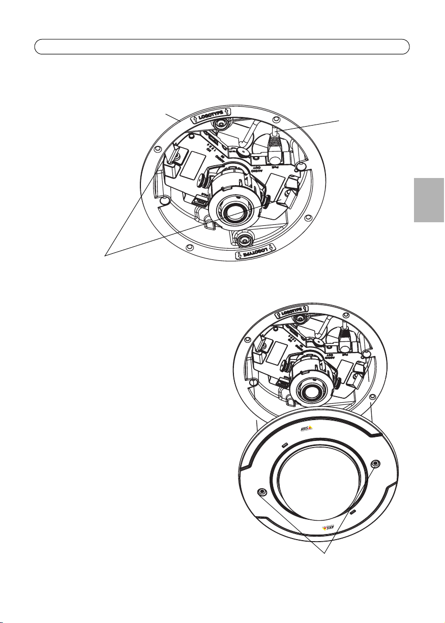
Network cable
Camera holders
Ceiling bracket
with camera
Captive screws
3. Connect the network cable to the camera, and then snap the camera into place in the ceiling
bracket.
4. Refer to the camera’s installation guide for instructions on how to install the camera.
5. Once the camera is installed and the view
angle adjusted, rotate the black protective
shield inside the plastic dome cover so it is
aligned with the camera’s position.
6. Place the plastic dome cover over the ceiling
bracket and tighten it into place using a
resitorx 20 (i.e. tamper proof) screwdriver.
7. The installation is now complete.
ENGLISH
Page 10

Page 11
Guide d'installation du kit de montage pour faux-plafond Page 11
Important !
Ce produit doit être utilisé
conformément aux lois et
dispositions locales en vigueur.
Guide d'installation du kit de montage pour
faux-plafond
Le présent guide fournit des instructions d'installation pour le kit de montage pour faux-plafond
pour les caméras réseau série AXIS P33. Lisez l'ensemble de ce guide avant de procéder à
l'installation.
Pour toute autre instruction d'utilisation de la caméra réseau
Axis, consultez le guide d'installation et le manuel de
l'utilisateur, disponibles sur le site www.axis.com/techsup
Procédure d'installation
• Vérifiez le contenu de l'emballage par rapport
à la liste de la page 12.
• Instructions d'installation. Reportez-vous à la page 14.
FRAN
Ç
AIS
Page 12
Page 12 Guide d'installation du kit de montage pour faux-plafond
Support pour installation au plafond
(vue de dessous)
La flèche du logo pointe vers l’endroit
Couvercle de dôme en plastique
Vis captives
Logo
Fil de sécurité
Support pour installation au plafond
(vue de dessus)
Bras de support
Vis du bras
de support
Autres trous
de vis (x4)
Joint de câble en caoutchouc
(câble non inclus)
où le logo apparait une fois
l’installation terminée
Contenu de l'emballage
• 1 couvercle de dôme en plastique
• 1 support pour installation au plafond
•1fil de sécurité+vis M4x6
• 2 joints en caoutchouc
• 1 modèle de trou
• 1 guide d'installation du kit de montage pour faux-plafond (le présent document)
Page 13
Guide d'installation du kit de montage pour faux-plafond Page 13
Support pour installation au plafond
(vue de dessus)
Couvercle de dôme en plastique
Trous de câble pour les joints
Support pour installation au plafond
(vue latérale)
Ø21 mm/0,8"
Ø191 mm/7,5"
159,3 mm/6,27"
85 mm/3,2"
63 mm/2,5"
10-60 mm/
0,4-2,4"
48 mm/1,9"
Caractéristiques techniques
• Poids total (caméra + kit de montage) : 0,9 kg (2,0 lb)
• Diamètre du couvercle de dôme en plastique : 191 mm (7,5")
• Diamètre du trou au plafond (partie supérieure du support) : 159,3 mm (6,4")
• Diamètre des trous de câble pour les joints (2 trous) : 21 mm (0,8")
• Épaisseur du plafond : de 10 à 60 mm (0,4" à 2,4") si vous utilisez les bras de support pour
fixer le kit de montage.
FRAN
Ç
AIS
Note:
La classification IP51 d´une installation utilisant des bras de support et des joints de câble
en caoutchouc s'applique uniquement à l'installation située au-dessus de la plaque du
faux-plafond.
Page 14
Page 14 Guide d'installation du kit de montage pour faux-plafond
Plaque de plafond
Diamètre du trou 159,3 mm/6,27"
À attacher au plafond
Trou de câble avec
joint en mousse noir
Installation du kit de montage pour faux-plafond
1. Retirez, si possible, la plaque de plafond à laquelle le kit de montage doit être fixé.
2. Utilisez le modèle fourni pour marquer l'emplacement du trou de 159,3 mm (6,27") dans la
plaque de plafond. Retirez le film protecteur, fixez le support sur la plaque et coupez en suivant
le modèle.
Remarques :
• Le poids total de la caméra et du kit de montage est de 0,9 kg (2,0 lb). Assurez-vous que le matériau
du plafond est suffisamment solide pour supporter ce poids.
• L'épaisseur de la plaque de plafond doit être comprise entre 10 et 60 mm (0,4" à 2,4").
• Assurez-vous que la surface est plane pour que le support soit parfaitement fixé et en toute sécurité.
3. Pour fixer la caméra à l'aide du fil de sécurité fourni, replacez la plaque de plafond et attachez
l'extrémité du fil de sécurité à un endroit adéquat sur le plafond, au-dessus du faux-plafond.
4. Acheminez le câble réseau via le trou dans le plafond.
5. Retirez les joints en mousse noirs des trous de câble situés dans le support.
Page 15

Guide d'installation du kit de montage pour faux-plafond Page 15
Câble réseau et joint en caoutchouc
Joint en
mousse
6. Pour une installation équipée d'une protection IP51,
préparez le câble réseau avec le joint en caoutchouc
fourni :
Faites passer délicatement le câble à travers le joint en
caoutchouc et branchez un connecteur réseau.
7. Connectez les deux trous de câble aux joints en
caoutchouc fournis.
Remarques :
• Au besoin, percez un trou dans le joint à l'aide du tournevis resitorx. N'utilisez pas de couteau ou
d'objet pointu.
• Ne forcez pas l'entrée du connecteur réseau via le joint
.
FRAN
Ç
AIS
De même, vous pouvez disposer le caoutchouc
en mousse noir autour du câble réseau et
placer l'ensemble dans le trou de câble.
Note:
L'installation et le joint en mousse noir ne
sont pas équipés d'une protection IP51.
Page 16

Page 16 Guide d'installation du kit de montage pour faux-plafond
Bras de support
Bras de support
Bord du caoutchouc noir
Vis du bras de
support
Autres trous
de vis (x4)
Fin de l'installation
1. Placez le support au plafond et positionnez les étiquettes du logo à l'endroit où vous souhaitez
que le logo apparaisse sur le couvercle en plastique.
2. Serrez les vis du bras de support à l'aide d'un tournevis torx 20. Les bras se déplient sur le
plafond et se bloquent. Assurez-vous que les vis sont serrées de manière homogène et en toute
sécurité, de sorte que le bord du caoutchouc noir soit parfaitement fixé à la plaque du fauxplafond.
De même, vous pouvez fixer le support pour plafond à l'aide de quatre autres trous de vis (cette
méthode n'est pas conforme à la norme IP51).
Note:
• Le cas échéant, utilisez des vis à tête plate afin de ne pas gêner l'attache du couvercle de dôme en
plastique.
Page 17

Guide d'installation du kit de montage pour faux-plafond Page 17
Câble réseau
Supports de caméra
Support pour installation
au plafond avec caméra
Vis captives
3. Connectez le câble réseau à la caméra, puis insérez la caméra dans le support.
4. Reportez-vous au guide d'installation de la caméra pour savoir comment installer la caméra.
5. Une fois la caméra installée et la mise au
point réglée, tournez l'écran protecteur noir à
l'intérieur du couvercle du dôme afin de
l'aligner sur la position de la caméra.
6. Placez le couvercle du dôme en plastique sur
le support de montage et serrez-le à l'aide
d'un tournevis resitorx 20 (pour vis
inviolables).
7. L'installation est maintenant terminée.
FRAN
Ç
AIS
Page 18

Page 19

Installationsanleitung für die Halterung für Hängedecken Seite 19
Wichtig!
Verwenden Sie dieses Produkt
unter Beachtung der geltenden
rechtlichen Bestimmungen.
Installationsanleitung für die Halterung für
Hängedecken
Diese Installationsanleitung enthält Anweisungen zur Montage der Halterung für Hängedecken für
die Netzwerk-Kameramodelle AXIS P33 serie. Bitte lesen Sie zunächst die Anleitung vollständig
durch, bevor Sie mit der Montage beginnen.
Alle weiteren Hinweise zur Verwendung der Axis NetzwerkKamera finden Sie in der Installationsanleitung und im
Benutzerhandbuch, die auf unserer Website unter
„www.axis.com/techsup“ zur Verfügung stehen.
Installationsschritte
• Prüfen Sie, ob alle in der
Liste auf page 20 aufgeführten Komponenten vorhanden sind.
• Befolgen Sie die Montageanweisungen. Weitere Informationen hierzu finden Sie auf
page 22.
DEUTSCH
Page 20

Seite 20 Installationsanleitung für die Halterung für Hängedecken
Deckenhalterung (unten)
LOGOTYPE-Pfeil zeigt auf die Stelle,
Kunststoff-Kuppelabdeckung
Unverlierbare
Schrauben
LOGOTYPE-Pfeil
Sicherheitsdraht
Deckenhalterung (oben)
Haltevorrichtungen
Schrauben für
Haltevorrichtung
4 alternative
Schraublöcher
Gummikabeldichtung
(Kabel nicht enthalten)
an der das Logo nach der Installation
erscheint
Inhalt des Produktpakets
• 1 Kunststoff-Kuppelabdeckung
• 1 Deckenhalterung
• 1 Sicherheitsdraht und M4x6-Schraube
• 2 Gummidichtungen
•1 Kreisschablone
• 1 Installationsanleitung für die Halterung für Hängedecken (dieses Dokument)
Page 21

Installationsanleitung für die Halterung für Hängedecken Seite 21
Deckenhalterung (oben)
Kunststoff-Kuppelabdeckung
Kabellöcher für Dichtungen
Deckenhalterung
(Seitenansicht)
Ø 21 mm
Ø 191 mm
159,3 mm
85 mm
63 mm
10 bis 60 mm
0.4-2.4”
48 mm
Spezifikationen
• Gesamtgewicht (Kamera plus Deckenhalterung): 0,9 kg
• Durchmesser der Kunststoff-Kuppelabdeckung: 191 mm
• Durchmesser des Lochs in der Decke (Deckenhalterung oben): 159,3 mm
• Durchmesser der Kabeldurchführung für Dichtung (2 Löcher): 21 mm
• Deckenstärke: 10 bis 60 mm, wenn Sie die Halterung für Hängedecken mit den Haltevor-
richtungen sichern.
Note:
Der IP51-Schutz durch Verwendung der Haltevorrichtungen und Gummikabeldichtungen
wird nur bei Anbringung über der Deckenplatte erzielt.
DEUTSCH
Page 22

Seite 22 Installationsanleitung für die Halterung für Hängedecken
Deckenplatte
Lochdurchmesser 159,3 mm
An Decke befestigen
Kabeldurchführung
mit schwarzer
Schaumstoffdichtung
Montage der Halterung für Hängedecken
1. Wenn möglich, nehmen Sie die Deckenplatte ab, in der die Halterung für Hängedecken angebracht werden soll.
2. Markieren Sie mithilfe der mitgelieferten Schablone die Position des 159,3-mm-Lochs in der
Deckenplatte. Ziehen Sie das Schutzpapier ab, fixieren Sie die Schablone auf der Deckenplatte
und schneiden Sie das Loch entlang der Schablone aus.
Hinweise:
• Das Gesamtgewicht von Kamera und Deckenhalterung beträgt 0,9 kg. Vergewissern Sie sich, dass das
Deckenmaterial stabil genug ist, um dieses Gewicht zu tragen.
• Die Stärke der Deckenplatte sollte zwischen 10 und 60 mm betragen.
• Stellen Sie sicher, dass die Oberfläche flach genug ist, sodass die Halterung sicher montiert werden
kann.
3. Um die Kamera mit dem beiliegenden Sicherheitsdraht zu sichern, setzen Sie die Deckenplatte
wieder ein und befestigen Sie das Ende des Sicherheitskabels mit dem Verschluss an einer
geeigneten Stelle in der Hängedecke.
Page 23

Installationsanleitung für die Halterung für Hängedecken Seite 23
Netzwerkkabel und Gummidichtung
Schaumstoffdichtung
4. Führen Sie das Netzwerkkabel durch das Loch in der Decke.
5. Entfernen Sie die schwarzen Schaumstoffdichtungen von den Kabellöchern in der Halterung.
6. Um den IP51-Schutz zu erzielen, bereiten Sie das
Netzwerkkabel mit einer Gummidichtung (im
Lieferumfang enthalten) vor:
Führen Sie das Kabel vorsichtig durch die
Gummidichtung und bringen Sie einen Netzwerkstecker
am Kabel an.
7. Drücken Sie die beiliegenden Gummidichtungen in die
beiden Kabellöcher.
Hinweise:
• Stechen Sie, falls nötig, mit dem Resitorx-Schraubendreher ein Loch in die Dichtung. Verwenden Sie
hierzu kein Messer oder einen anderen scharfen Gegenstand.
• Versuchen Sie nicht, den Netzwerkstecker durch die Dichtung zu führen.
DEUTSCH
Legen Sie alternativ die schwarze
Schaumstoffdichtung um das
Netzwerkkabel und führen Sie sie
zusammen mit dem Netzwerkkabel in die
Kabeldurchführung.
Note:
Die Montage mit der schwarzen
Schaumstoffdichtung entspricht nicht
dem Schutz nach IP51.
Page 24

Seite 24 Installationsanleitung für die Halterung für Hängedecken
Haltevorrichtung
Haltevorrichtung
Schwarzer Gummirand
Schrauben für
Haltevorrichtung
4 alternative
Schraublöcher
Montage abschließen
1. Platzieren Sie die Deckenhalterung in der Decke und positionieren Sie die LOGOTYPE-Etiketten
an der für das Logo auf der Kunststoffabdeckung vorgesehenen Stelle.
2. Ziehen Sie die Schrauben der Haltevorrichtung mit einem Torx-Schraubenzieher für Torx 20Schrauben fest. Die Haltevorrichtungen werden oberhalb der Decke ausgeklappt und arretieren
dadurch die Deckenhalterung an der richtigen Position. Vergewissern Sie sich, dass die
Schrauben sicher und gleichmäßig festgezogen werden, sodass der schwarze Gummirand
vollständig auf der Deckenplatte sitzt.
Alternativ können Sie die Deckenhalterung mithilfe der vier alternativen Schraublöcher befestigen
(diese Methode entspricht nicht dem Schutz nach IP51).
Note:
• Verwenden Sie Flachkopfschrauben für die Anbringung der Halterung für Hängedecken mit den
alternativen Schraublöchern, damit keine Probleme bei der Befestigung der KunststoffKuppelabdeckung auftreten.
Page 25

Installationsanleitung für die Halterung für Hängedecken Seite 25
Netzwerkkabel
Deckenhalterung
mit Kamera
Kamerahalter
Unverlierbare Schrauben
3. Schließen Sie das Netzwerkkabel an der Kamera an und lassen Sie anschließend die Kamera in
der Deckenhalterung einrasten.
4. Entsprechende Anweisungen zur Installation der Kamera finden Sie in der Installationsanleitung
der Kamera.
5. Nachdem Sie die Kamera installiert und den
Sichtwinkel eingestellt haben, passen Sie die
schwarze Schutzabdeckung in der KunststoffKuppelabdeckung durch Drehen an die
Kameraposition an.
6. Platzieren Sie die KunststoffKuppelabdeckung auf der Deckenhalterung
und befestigen Sie sie mit einem Resitorx 20Schraubenzieher (manipulationsgeschützt).
7. Die Installation ist damit abgeschlossen.
DEUTSCH
Page 26

Page 27

Guida all'installazione per il montaggio su controsoffitto Pagina 27
Importante!
Questo prodotto deve essere
usato in conformità alle leggi e
ai regolamenti locali.
Guida all'installazione per il montaggio su
controsoffitto
Questa guida all'installazione fornisce le istruzioni per il montaggio su controsoffitto delle
telecamere di rete serie AXIS P33. Leggere per intero la guida all'installazione prima di procedere
con l'installazione.
Per altre informazioni relative all'utilizzo delle telecamere di
rete di Axis, consultare la Guida all'installazione e la Guida
per l'utente disponibili sul sito web www.axis.com/techsup.
Procedura di installazione
• Controllare il contenuto della confezione utilizzando
l'elenco a page 28.
• Istruzioni per l'installazione. Vedere a page 30.
ITALIANO
Page 28

Pagina 28 Guida all'installazione per il montaggio su controsoffitto
Staffa per il montaggio a soffitto (basso)
La freccia del logo diretta dove
Copertura della cupola in plastica
Viti imperdibili
Logo
Cavo di
Staffa per il montaggio a soffitto (alto)
Braccia di
supporto
Viti del braccio
di supporto
Fori alternativi
per le viti (4x)
Guarnizione in gomma per il cavo
(cavo non incluso)
sicurezza
apparirà il logo quando l’installazione
é completa
Contenuto della confezione
• 1 Copertura della cupola in plastica
• 1 Staffa per soffitto
• 1 Filo di sicurezza e vite M4x6
• 2 Guarnizioni in gomma
• 1 Maschera per foratura
• 1 Guida all'installazione per il montaggio su controsoffitto (questo documento)
Page 29

Guida all'installazione per il montaggio su controsoffitto Pagina 29
Staffa per il montaggio a soffitto (alto)
Copertura della cupola in plastica
Fori dei cavi per le guarnizioni
Staffa per il montaggio a soffitto (vista laterale)
Ø21 mm
Ø191 mm
159,3 mm
85 mm
63 mm
10-60 mm
48 mm
Specifiche
• Peso totale (telecamera e montaggio a soffitto): 0,9 kg
• Diametro della copertura della cupola in plastica. 191 mm
• Diametro del foro per soffitto (parte superiore della staffa per soffitto): 159,3 mm
• Diametro del foro del cavo per la guarnizione (2 fori): 21 mm
• Spessore del soffitto: 10-60 mm, se si utilizzano le braccia di supporto per fissare in
posizione il montaggio a controsoffitto
Note:
La classe IP51 dell'installazione mediante bracci di supporto e guarnizioni per cavi in
gomma e' valida solo per l'installazione sopra il pannello del soffitto.
ITALIANO
Page 30

Pagina 30 Guida all'installazione per il montaggio su controsoffitto
Pannello del soffitto
Diametro del foro 159,3 mm
Fissare al soffitto
Foro del cavo con guarnizione
in spugna nera
Installazione per il montaggio su controsoffitto
1. Se possibile, rimuovere il pannello del soffitto su cui deve essere eseguito il montaggio.
2. Utilizzare la maschera fornita per contrassegnare la posizione del foro da 159,3 mm nel
pannello del soffitto. Rimuovere la carta protettiva, fissare al pannello del soffitto e tagliare
intorno al modello.
Note:
• Il peso totale della telecamera del supporto per il montaggio a soffitto è di 0,9 kg. Controllare che il
materiale del soffitto sia sufficientemente robusto per sostenere tale peso.
• Lo spessore del pannello del soffitto deve essere compreso fra 10 e 60 mm.
• Assicurarsi che la superficie sia piana, in modo che la staffa sia fissata tutto intorno.
3. Per fissare la telecamera usando il filo di sicurezza fornito, sostituire il pannello del soffitto e
fissare l'estremità del filo di sicurezza a un punto adatto del soffitto, sopra il controsoffitto.
4. Far passare il cavo di rete attraverso il foro del soffitto.
5. Rimuovere le guarnizioni in spugna nera dai fori dei cavi nella staffa.
Page 31

Guida all'installazione per il montaggio su controsoffitto Pagina 31
Cavo di rete e guarnizione in gomma
Guarnizione
in spugna
6. Per un'installazione di classe IP51, preparare il cavo di
rete con una guarnizione in gomma (fornita):
Spingere delicatamente il cavo nella guarnizione in
gomma e fissarlo al connettore di rete.
7. Tappare entrambi i fori dei cavi con le guarnizioni in
gomma fornite.
Notes:
• Se necessario, praticare un foro nella guarnizione con il cacciavite resitorx, non usare un coltello o un
altro oggetto affilato.
• Non spingere a forza il connettore di rete attraverso la guarnizione
In alternativa, adattare la guarnizione di spugna
nera intorno al cavo di rete e collocare la
guarnizione di spugna nel foro del cavo, insieme
al cavo di rete.
Note:
L'installazione con la guarnizione di spugna
nera non è di classe IP51.
ITALIANO
Page 32

Pagina 32 Guida all'installazione per il montaggio su controsoffitto
Braccio di supporto
Braccio di supporto
Orlo di gomma nera
Viti del braccio di
supporto
Fori alternativi
per le viti (4x)
Completamento dell'installazione
1. Collocare la staffa nel soffitto e posizionare le etichette del logo dove si desidera che i logotipi
appaiano sul coperchio di plastica.
2. Serrare le viti del braccio del supporto usando un cacciavite torx 20. Le braccia si piegheranno
sul soffitto e si bloccheranno in posizione. Assicurarsi che le viti siano strette in modo saldo e
uniforme, facendo in modo che l'orlo di gomma nera sia completamente fissato al pannello del
soffitto.
In alternativa, fissare la staffa a soffitto usando i quattro fori alternativi per le viti (questo metodo
non è di classe IP51).
Note:
• Se si fissa il montaggio a soffitto con i fori alternativi per le viti, usare viti a testa piatta che non
ostruiscano il coperchio in plastica della cupola.
Page 33

Guida all'installazione per il montaggio su controsoffitto Pagina 33
Cavo di rete
Supporti della
telecamera
Staffa per il montaggio a soffitto
con telecamera
Viti prigioniere
3. Collegare il cavo di rete alla telecamera, quindi far scattare la telecamera in posizione nella
staffa a soffitto.
4. Per istruzioni sull'installazione della telecamera, consultare la guida all'installazione della
telecamera.
5. Una volta che la telecamera è stata installata
e l'angolo visuale è stato regolato, ruotare la
schermatura protettiva nera nel coperchio in
plastica della cupola, in modo che sia allineato
con la posizione della telecamera.
6. Collocare il coperchio a cupola in plastica
sulla staffa per soffitto e farlo scattare in
posizione usando un cacciavite resitorx 20
(cioè un cacciavite antimanomissione).
7. A questo punto l'installazione è completata.
ITALIANO
Page 34

Page 35

Guía de instalación del montaje del falso techo Página 35
¡Importante!
Este producto debe utilizarse de
acuerdo con la legislación y
normativas locales.
Guía de instalación del montaje del falso techo
Esta guía de instalación incluye instrucciones para instalar el montaje del falso techo en las
cámaras de red serie AXIS P33. Lea toda la guía antes de iniciar la instalación.
Para otras cuestiones relacionadas con el uso de la cámara
de red Axis, consulte la Guía de instalación y el Manual del
usuario, disponibles en www.axis.com/techsup.
Pasos para la instalación
• Verifique el contenido del paquete de acuerdo con
la lista que aparece en la page 36.
• Instrucciones para la instalación. Véase la page 38.
ESPAÑOL
Page 36

Página 36 Guía de instalación del montaje del falso techo
Soporte del techo
(inferior)
Las flechas del logotipo
Cubierta de plástico del domo
Tornillos
cautivos
Logotipo
Cable de
Soporte del techo
(superior)
Brazos de
soporte
Tornillos para el
brazo de soporte
Agujeros para los
tornillos
alternativos (4x)
Junta de cable de goma
(cable no incluido)
seguridad
señalan el lugar en el que
aparecerá el logotipo una
vez finalizada la instalación
Contenido del paquete
• 1 cubierta de plástico del domo
• 1 soporte del techo
• 1 cable de seguridad y tornillo M4x6
• 2 juntas de goma
• 1 plantilla del agujero
• 1 guía de instalación del montaje del falso techo (este documento)
Page 37

Guía de instalación del montaje del falso techo Página 37
Soporte del techo
(superior)
Cubierta de plástico del domo
Agujeros del cable para las juntas
Soporte del techo
(vista lateral)
Ø21 mm/0,8”
Ø191 mm/7,5”
159,3 mm/6,27”
85 mm/3,5”
63 mm/2,5”
10-60 mm/
0,4-2,4”
48 mm/1,9”
Especificaciones
• Peso total (cámara y montaje del techo): 0,9 kg (2,0 libras)
• Diámetro de la cubierta de plástico del domo: 191 mm (7,5”)
• Diámetro del agujero del techo (parte superior del soporte del techo): 159,3 mm (6,27”)
• Diámetro del agujero del cable para la junta (2 agujeros): 21 mm (0.8“)
• Grosor del techo: entre 10 y 60 mm (entre 0,4” y 2,4”) si utiliza los brazos de soporte para
fijar el montaje del falso techo.
Nota:
La clasificación IP51 de la instalación utilizando los brazos de soporte y juntas de cable de
goma sólo afecta la instalación por encima de la placa del techo.
ESPAÑOL
Page 38

Página 38 Guía de instalación del montaje del falso techo
Placa del techo
Diámetro del agujero 159,3 mm (6,27”)
Fijación al techo
Agujero del cable con
junta de espuma negra
Instalación del montaje del falso techo
1. Si es posible, retire la placa del techo donde se instalará el montaje del falso techo.
2. Utilice la plantilla proporcionada para marcar la posición del agujero de 159,3 mm (6,27”) en la
placa del techo. Retire el papel protector, fíjela en la placa y corte alrededor de la plantilla.
Notas:
• El peso de la cámara junto con el montaje del techo es de 0,9 kg (2,0 libras). Asegúrese de que el
material del techo puede aguantar este peso.
• El grosor de la placa del techo debería ser de entre 10 y 60 mm (0,4” y 2,4”).
• Asegúrese de que la superficie es plana para que el soporte encaje con seguridad en todo su
alrededor.
3. Para fijar la cámara mediante el cable de seguridad suministrado, cambie la placa del techo e
inserte el extremo del cable de seguridad en un punto adecuado del techo por encima del falso
techo.
Page 39

Guía de instalación del montaje del falso techo Página 39
Cable de red y junta de goma
Junta de
espuma
4. Pase los cables de red por el agujero del techo.
5. Retire la junta de espuma negra del agujero del cable en el soporte.
6. Para una instalación de clase IP51, prepare el cable de
red con una junta de goma (suministrada):
Fuerce suavemente el cable a través de la junta de goma
y acople un conector de red.
7. Conecte ambos orificios para cable con la junta de goma
suministrada.
Notas:
• Si es necesario, perfore un orificio en la junta con el destornillador resitorx, no utilice un cuchillo ni
otro objeto afilado.
• No fuerce el conector de red en la junta.
Como alternativa, ponga la junta de espuma
negra alrededor del cable de red y coloque la
junta de espuma y el cable de red en el orificio
del cable.
Nota:
La instalación con junta de espuma negra no
es de clase IP51.
ESPAÑOL
Page 40

Página 40 Guía de instalación del montaje del falso techo
Brazo de soporte
Brazo de soporte
Borde de goma negro
Tornillos para el
brazo de soporte
Agujeros alternativos
para los tornillos (4x)
Finalización de la instalación
1. Coloque el soporte del techo mirando hacia el techo y sitúe las etiquetas del logotipo en la
parte de la cubierta de plástico que desee.
2. Apriete los tornillos para el brazo de soporte con un destornillador torx 20. Los brazos se
desplegarán en el techo y se fijarán. Asegúrese de que los tornillos están apretados de manera
segura y uniforme y que el borde de goma está completamente fijado en la placa del techo.
Como alternativa, fije el soporte del techo utilizando los cuatro agujeros alternativos (este método
no es de clase IP51).
Nota:
• Si fija el montaje del falso techo mediante los agujeros para los tornillos alternativos, utilice tornillos
de cabeza plana que no obstruirán el montaje de la cubierta de plástico del domo.
Page 41

Guía de instalación del montaje del falso techo Página 41
Cable de red
Soportes de la
cámara
Soporte del techo
con cámara
Tornillos cautivos
3. Conecte el cable de red a la cámara y coloque la cámara en el soporte del techo.
4. Consulte la guía de instalación de la cámara para obtener instrucciones sobre cómo instalar la
cámara.
5. Una vez haya instalado la cámara y haya
ajustado el ángulo de visión, gire el
revestimiento de protección negro del interior
de la cubierta de plástico del domo para que
coincida con la posición de la cámara.
6. Coloque la cubierta de plástico del domo por
encima del soporte del techo y apriétela con
un destornillador resitorx 20 (por ejemplo, de
alta resistencia).
7. La instalación ha finalizado.
ESPAÑOL
Page 42

Page 43

Page 44

Installation Guide Ver.6.0
Drop Ceiling Mount for AXIS P33 Network Camera Series Printed: July 2015
© Axis Communications AB, 2009-2015 Part No. 1491581
 Loading...