

Axis P3354 Installation Guide

INSTALLATION GUIDE
AXIS P3353 Network Camera
AXIS P3354 Network Camera
AXIS P3363-V Network Camera
AXIS P3364-V Network Camera
ENGLISH DEUTSCH
FRAN
Ç
AIS
ITALIANO
ESPAÑOL
About this Document
Japan -
この装置は、クラスB 情報技術装置です。
この装置は、家庭環境で使用することを目 的として
いますが、この装置がラジオやテレビジョン受信機
に近接して使用されると、 受信障害を引き起こすこ
とがあります。 取扱説明書に従って正しい取り扱い
をして下さい。
This document includes instructions for installing the AXIS
P3353/P3354/P3363-V/P3364-V on your network. Previous
experience of networking will be beneficial when installing
the product.
Legal Considerations
Video and audio surveillance can be prohibited by laws that
vary from country to country. Check the laws in your local
region before using this product for surveillance purposes.
This product includes one (1) H.264 decoder license. To
purchase further licenses, contact your reseller.
Electromagnetic Compatibility (EMC)
This equipment has been designed and tested to fulfill
applicable standards for:
Radio frequency emission when installed according to the
instructions and used in its intended environment.
Immunity to electrical and electromagnetic phenomena
when installed according to the instructions and used in its
intended environment.
USA - Depending on the characteristics of the electrical
environment, using shielded cables (STP) may be
appropriate, in which case the following is applicable: This
equipment has been tested using shielded cables (STP) and
found to comply with the limits for a Class B digital device,
pursuant to part 15 of the FCC Rules. These limits are
designed to provide reasonable protection against harmful
interference in a residential installation. This equipment
generates, uses and can radiate radio frequency energy and,
if not installed and used in accordance with the
instructions, may cause harmful interference to radio
communications. However, there is no guarantee that
interference will not occur in a particular installation. If this
equipment does cause harmful interference to radio or
television reception, which can be determined by turning
the equipment off and on, the user is encouraged to try to
correct the interference by one or more of the following
measures:
Reorient or relocate the receiving antenna.
Increase the separation between the equipment and
receiver.
Connect the equipment into an outlet on a circuit different
from that to which the receiver is connected.
Consult the dealer or an experienced radio/TV technician for
help
Canada - This Class B digital apparatus complies with
Canadian ICES-003.
Europe - This digital equipment fulfills the
requirements for RF emission according to the Class B limit
of EN 55022.
This product fulfills the requirements for immunity
according to EN 61000-6-1 residential, commercial and
light-industry environments.
This product fulfills the requirements for immunity
according to EN 61000-6-2 industrial environments.
This product fulfills the requirements for immunity
according to EN 55024 office and commercial
environments.
Australia - This digital equipment fulfills the
requirements for RF emission according to the Class B limit
of AS/NZS CISPR 22.
Equipment Modifications
This equipment must be installed and used in strict
accordance with the instructions given in the user
documentation. This equipment contains no
user-serviceable components. Unauthorized equipment
changes or modifications will invalidate all applicable
regulatory certifications and approvals.
Liability
Every care has been taken in the preparation of this
document. Please inform your local Axis office of any
inaccuracies or omissions. Axis Communications AB cannot
be held responsible for any technical or typographical errors
and reserves the right to make changes to the product and
documentation without prior notice. Axis Communications
AB makes no warranty of any kind with regard to the
material contained within this document, including, but not
limited to, the implied warranties of merchantability and
fitness for a particular purpose. Axis Communications AB
shall not be liable nor responsible for incidental or
consequential damages in connection with the furnishing,
performance or use of this material.
RoHS
This product complies with both the European RoHS
directive, 2002/95/EC, and the Chinese RoHS
regulations, ACPEIP.
WEEE Directive
The European Union has enacted a Directive
2002/96/EC on Waste Electrical and Electronic
Equipment (WEEE Directive). This directive is
applicable in the European Union member states.
The WEEE marking on this product (see right) or
its documentation indicates that the product must not be
disposed of together with household waste. To prevent
possible harm to human health and/or the environment, the
product must be disposed of in an approved and
environmentally safe recycling process. For further
information on how to dispose of this product correctly,
contact the product supplier, or the local authority
responsible for waste disposal in your area.
Business users should contact the product supplier for
information on how to dispose of this product correctly. This
product should not be mixed with other commercial waste.
For more information, visit
www.axis.com/techsup/commercial waste
Support
Should you require any technical assistance, please contact
your Axis reseller. If your questions cannot be answered
immediately, your reseller will forward your queries through
the appropriate channels to ensure a rapid response. If you
are connected to the Internet, you can:
• download user documentation and firmware updates
• find answers to resolved problems in the FAQ database.
Search by product, category, or phrases
• report problems to Axis support by logging in to your
private support area.

Safeguards
Please read through this Installation Guide carefully before installing the product. Keep the Installation Guide
for further reference.
CAUTION!
• When transporting the Axis product, use the original packaging or equivalent to prevent damage to the
product.
• Store the Axis product in a dry and ventilated environment.
• Avoid exposing the Axis product to vibration, shocks or heavy pressure and do not install the camera on
unstable brackets, unstable or vibrating surfaces or walls, since this could cause damage to the product.
• Only use hand tools when installing the Axis product, the use of electrical tools or excessive force could
cause damage to the product.
• Do not use chemicals, caustic agents, or aerosol cleaners. Use a damp cloth for cleaning.
• Use only accessories that comply with technical specification of the product. These can be provided by Axis
or a third party.
• Use only spare parts provided by or recommended by Axis.
• Do not attempt to repair the product by yourself; contact Axis or your Axis reseller for service matters.
IMPORTANT!
• This Axis product must be used in compliance with local laws and regulations.
• To use this Axis product outdoors, it must be installed in an approved outdoor housing.
Battery replacement
This Axis product uses a 3.0V CR2032 Lithium battery as the power supply for its internal real-time clock (RTC).
Under normal conditions this battery will last for a minimum of 5 years. Low battery power affects the
operation of the RTC, causing it to reset at every power-up. A log message will appear when the battery needs
replacing. The battery should not be replaced unless required!
If the battery does need replacing, please contact www.axis.com/techsup for assistance.
• Danger of Explosion if battery is incorrectly replaced.
• Replace only with the same or equivalent battery, as recommended by the manufacturer.
• Dispose of used batteries according to the manufacturer's instructions.
ENGLISH
Cleaning of dome cover
• Be careful not to scratch or damage the dome cover. Do not clean a dome cover that looks clean to the eye
and never polish the surface. Excessive cleaning can damage the surface.
• For general cleaning of a dome cover it is recommended to use a non-abrasive, solvent-free neutral soap or
detergent with water and a soft cloth. Rinse well with clean lukewarm water. Dry with a soft cloth to prevent water spotting.
• Never use harsh detergents, gasoline, benzene or acetone etc. and avoid cleaning in direct sunlight or at
elevated temperatures.

AXIS P33 Network Camera Installation Guide Page 5
AXIS P3353/P3354/P3363-V/P3364-V Network
Camera Installation Guide
This installation guide provides instructions for installing an AXIS P33 Network Camera on your
network. For all other aspects of using the product, please see the User Manual, available on
www.axis.com
1.
“Package contents”
“Hardware overview”
2.
3.
“Mount the camera”
“Assign an IP address”
4.
“Set the password”
5.
6.
“Adjust the Lens”
“Complete the installation”
7.
Notes:
• Before you begin, make sure that the package contents, the required cables, tools,
and documentation are available. See
• This network camera is intended to operate with PoE; if not available use AXIS PoE Midspan 1 port (not
included).
on page 5
on page 6
on page 7
on page 8
on page 11
on page 13
Package contents
on page 14
below.
ENGLISH
Package contents
Item Models/variants/notes
Network camera AXIS P3353, AXIS P3354, AXIS P3363-V
Dome covers Clear transparent cover
Labels 2 adhesive serial no. labels
Mounting kit Resitorx screw driver, drill template, terminal block connector
CD AXIS Network Video Product CD including installation tools and other
Printed materials Installation Guide (this document)
Optional accessories Mounting bracket (region specific)
AXIS P3364-V
Smoked transparent cover
software
Axis Warranty Document
AVHS Authentication key
See www.axis.com for information on available accessories

Page 6 AXIS P33 Network Camera Installation Guide
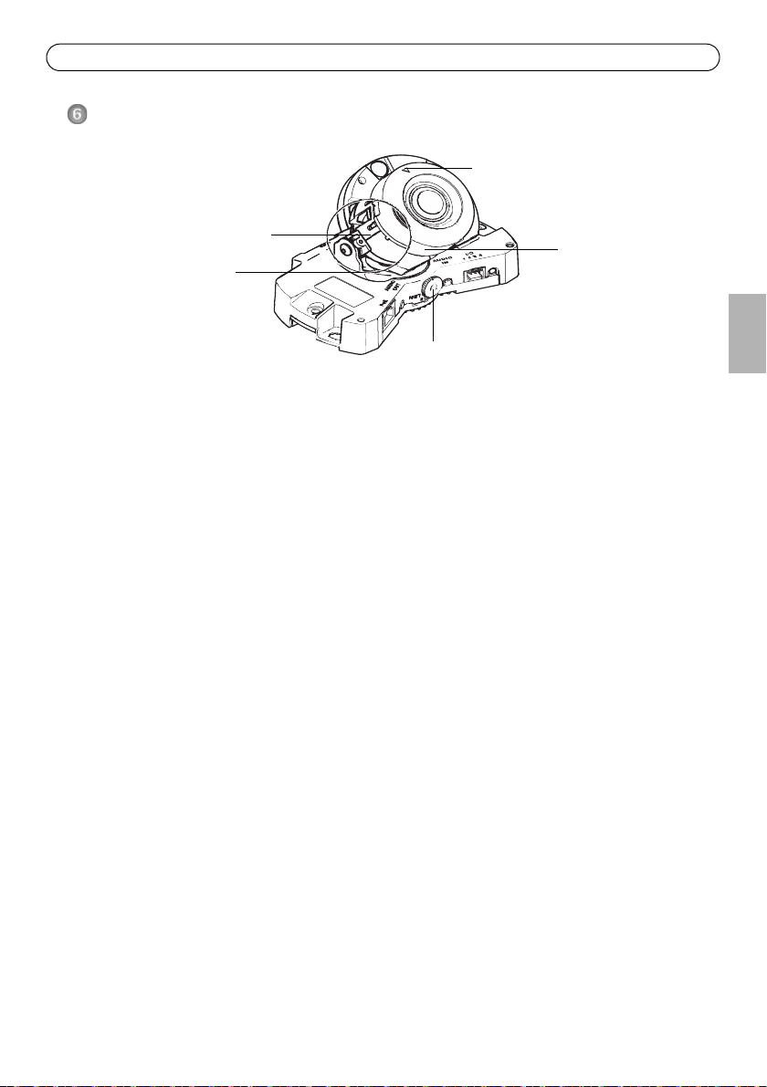
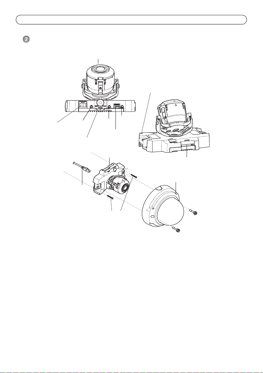
Network connector
LED indicators
I/O connector
(PoE)
Camera unit
Network cable
Dome cover
out
Audio in
SD memory card slot
Wall screws
Audio
Camera unit
Fan output
connector
Built-in microphone
Control button
Camera: P3363/P3364
Hardware overview
Note: AXIS P3353 and AXIS P3354 do not support I/O or audio.
Dimension (HxWxD)
AXIS P3353/AXIS P3354/AXIS P3363-V /AXIS P3364-V = 97 x 148 x 148 mm (3.82 x 5.83 x 5.83")
Weight
AXIS P3353/AXIS P3354 = 430 g (0.9 lb.)
AXIS P3363-V /AXIS P3364-V = 650 g (1.4 lb.)
AXIS P33 Network Camera Installation Guide Page 7
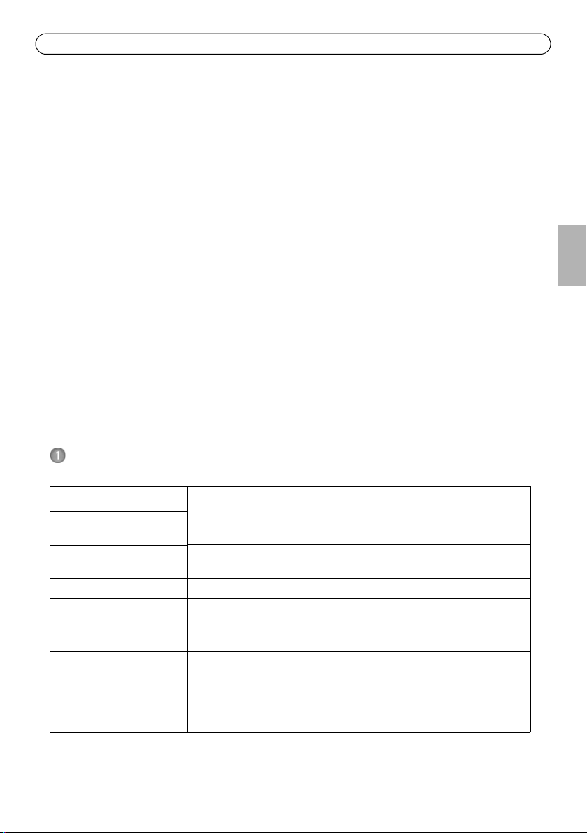
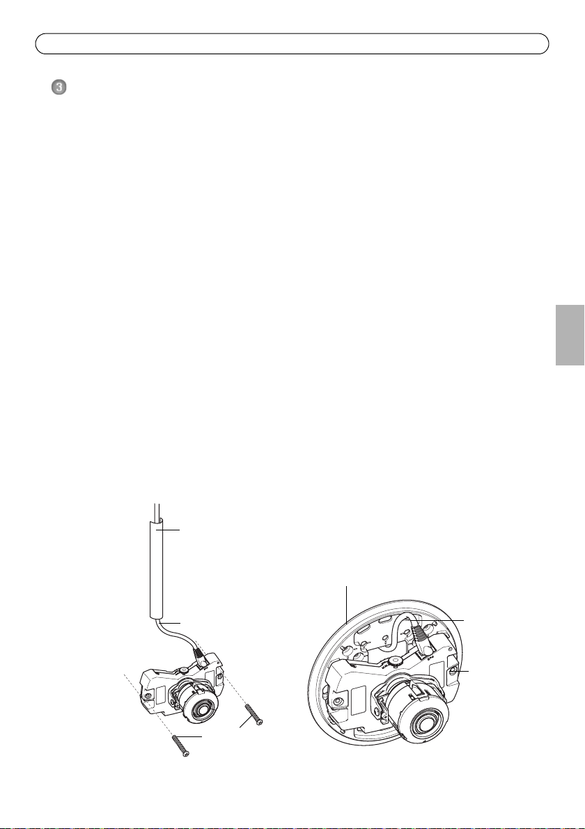
Metal conduit (Optional/not included)
Mounting bracket (Optional/not included)
Network cable
M4x8 screw
Wall screws
Network cable
Mount the camera
This Axis product can be mounted with the cables routed through or along the wall. This product
can also be fitted with a metal conduit for protecting the cabling when they are routed along the
wall. See the illustration that follows.
Mount camera directly onto the wall
1. Using the drill template drill 2 holes in the wall.
2. Route and connect the network cable.
3. Attach the camera unit to the wall using screws and plugs appropriate for the wall material.
Mount camera using a mounting bracket (not included)
1. Using the drill template drill 2 holes in the wall.
2. Route the network cable through the wall and through the holes in the mounting bracket.
3. Attach the mounting bracket to the wall, using screws and plugs appropriate for the wall
material.
4. Connect the network cable.
5. Optionally connect the I/O and audio cables; see page 17 for details.
6. Optionally insert the SD memory card.
7. Attach the camera unit to the mounting bracket using two appropriate screws.
Note:
• These instructions are for mounting the camera on a wall. The mounting bracket can also be used for
mounting the network camera to a junction box.
• AXIS P3353 and AXIS P3354 do not support audio and I/O.
ENGLISH

Page 8 AXIS P33 Network Camera Installation Guide
Assign an IP address
The network camera is designed for use on an Ethernet network and requires an IP address for
access. Most networks today have a DHCP server that automatically assigns IP addresses to
connected devices. If your network does not have a DHCP server, the network camera will use
192.168.0.90 as the default IP address.
AXIS IP Utility and AXIS Camera Management are the recommended methods for setting an IP
address in Windows. These free applications are available on the Axis Network Video Product CD
supplied with this product, or they can be downloaded from www.axis.com/techsup
Depending on the number of cameras you wish to install, use the method that suits you best.
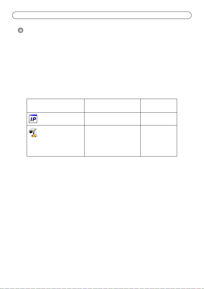
Method Recommended for Operating system
AXIS IP Utility
See page 9
AXIS Camera Management
See page 10
Notes:
• If you are unable to set the IP address, check for any firewall blocking the operation.
• See page 15 for other available methods for setting or discovering the IP address of the network camera,
in relation to other operating systems.
Single camera
Small installations
Multiple cameras
Large installations
Installation on a different subnet
Windows
Windows 2000
Windows XP Pro
Windows 2003 Server
Windows 2008 Server
Windows Vista
Windows 7

AXIS P33 Network Camera Installation Guide Page 9
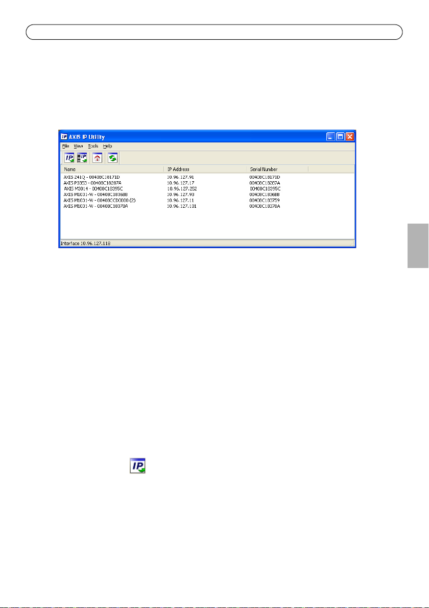
AXIS IP Utility - single camera/ small installation
AXIS IP Utility automatically discovers and displays Axis devices on your network. You can also
manually set a static IP address through this application. AXIS IP Utility is available on the Axis
Network Video Product CD, or it can be downloaded from www.axis.com/techsup
Note that you must install the network camera on the same network segment (physical subnet) as
the computer running AXIS IP Utility.
Automatic discovery
1. Check that the network camera is connected to the network and that power has been applied.
2. Start AXIS IP Utility.
3. When the camera’s name appears in the window, double-click to open the camera’s home page.
4. See page 11 for instructions on how to set the password.
ENGLISH
Set the IP address manually (optional)
1. Acquire an unused IP address on the same network segment your computer is connected to.
2. Select the network camera in the list.
3. Click the button Assign new IP address to selected device - and enter the serial number
and IP address for the network camera. The serial number is located on the product label.
4. Click the Assign button and follow on-screen instructions. Note that the camera must be
restarted within two minutes for the new IP address to be set.
5. Click the Home Page button to access the camera’s web pages.
6. See page 11 for instructions on how to set the password.
Page 10 AXIS P33 Network Camera Installation Guide
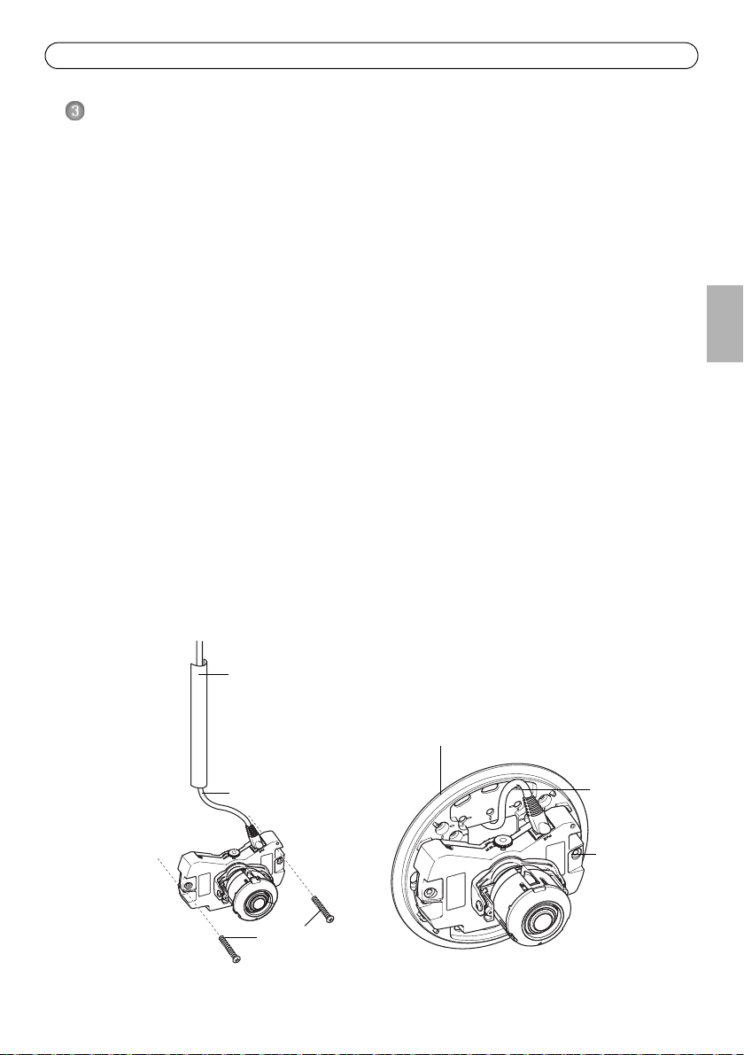
AXIS Camera Management - multiple cameras/large installations
AXIS Camera Management can automatically discover multiple Axis devices, show connection
status, manage firmware upgrades and set IP addresses.
Automatic discovery
1. Check that the camera is connected to the network and that power has been applied.
2. Start AXIS Camera Management. When the camera appears in the window, right-click the link
and select Live View Home Page.
3. See page 11 for instructions on how to set the password.
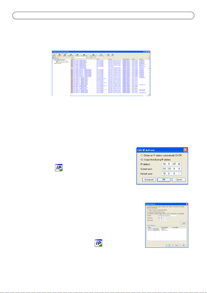
Assign an IP address in a single device
1. Select the camera in AXIS Camera Management and click the
Assign IP button .
2. Select Assign the following IP address and enter the IP
address, the subnet mask, and default router the device will
use.
3. Click OK.
Assign IP addresses in multiple devices
AXIS Camera Management speeds up the process of assigning IP
addresses to multiple devices, by suggesting IP addresses from a
specified range.
1. Select the devices you wish to configure (different models can be
selected) and click the Assign IP button .
2. Select Assign the following IP address range and enter the range
of IP addresses, the subnet mask, and default router the devices will use.
3. Click the OK button.
AXIS P33 Network Camera Installation Guide Page 11
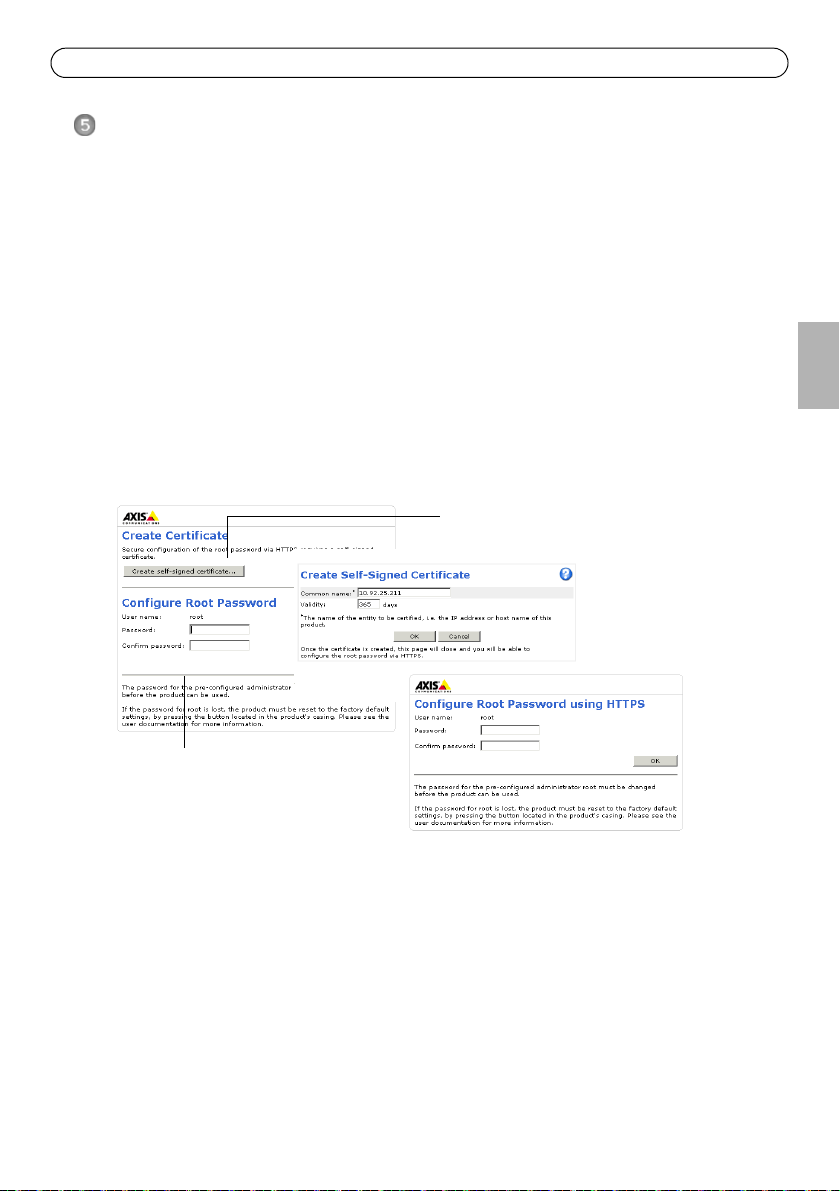
To configure the password directly via an
unencrypted connection, enter the
password here.
To create an HTTPS connection, start by
clicking this button.
Set the password
To gain access to the product, the password for the default administrator user root must be set. This
is done in the Configure Root Password dialog, which is displayed when the network camera is
accessed for the first time.
To prevent network eavesdropping when setting the root password, this can be done via an
encrypted HTTPS connection, which requires an HTTPS certificate.
To set the password via a standard HTTP connection, enter it in the Configure Root Password
window. To set the password via an encrypted HTTPS connection, follow these steps:
1. Click the Create self-signed certificate button.
2. Provide the requested information and click OK. The certificate is created and the password can
now be set securely. All traffic to and from the network camera is encrypted from this point on.
3. Enter a password and then re-enter to confirm the spelling. Click OK. The password has now
been configured.
ENGLISH
4. To log in, enter the user name “root” in the dialog as requested.
The default administrator user name root cannot be deleted.
Note:
5. Enter the password as set above, and click OK. If the password is lost, the network camera must
be reset to the factory default settings. See page 19.
If required, click Yes to install AMC (AXIS Media Control), which allows viewing of the video stream
in Internet Explorer. You will need administrator rights on the computer to do this.
To install AMC in Windows 7/Windows Vista, you must run Internet Explorer as administrator.
Note:
Right-click the Internet Explorer icon and select Run as administrator.

Page 12 AXIS P33 Network Camera Installation Guide
6. Select the power line frequency (50 Hz or 60 Hz) used
in your location
from the drop-down list the first time
network camera is accessed.
Power line frequency can be changed from Plain Con-
Note:
fig or by resetting the product to factory default.
Selecting the wrong frequency will cause image flicker
if the product is used in fluorescent light environments. When using 50 Hz, the maximum frame
rate is limited to 25 fps.
Access the video stream
The Live View page of the network camera is displayed with links to the setup tools which allow
you to customize the camera.
If required, click Yes to install AMC (AXIS Media Control), which allows viewing of the video stream
in Internet Explorer. You will need administrator rights on the computer to do this.
Note: To install AMC in Windows 7/Windows Vista, you must run Internet Explorer as an administrator.
Right-click the Internet Explorer icon and select Run as administrator.
AXIS P33 Network Camera Installation Guide Page 13
Locking screw
Lens holder
Lens
Horizontal line
Mark
Adjust the Lens
Open the Live View page in the web interface and make the following adjustments to the camera:
1. Loosen the locking screw.
2. Turn the lens holder to the desired position.
3. Turn the lens to ensure the (horizontal) lines on either side of the lens are aligned horizontally.
Ensure that the mark on the lens cover, between the horizontal lines, is facing up.
Note:
4. Once satisfied, gently tighten the locking screw to secure the camera’s position.
5. Open the Focus Adjustment page in the Web interface under Setup > Basic Setup > Focus &
Zoom, and follow the on-screen instructions. Use the image window to adjust the zoom and
focus. See the online help files for more information.
ENGLISH
Note:
• Due to the dome’s refraction, the image may appear slightly out of focus once the dome has been placed.
To correct this go to the Focus Adjustment page in the Web interface under Setup > Basic Setup >
Focus & Zoom, and adjust the focus again.
Warning! Adjusting the focus and zoom manually can damage the lens.
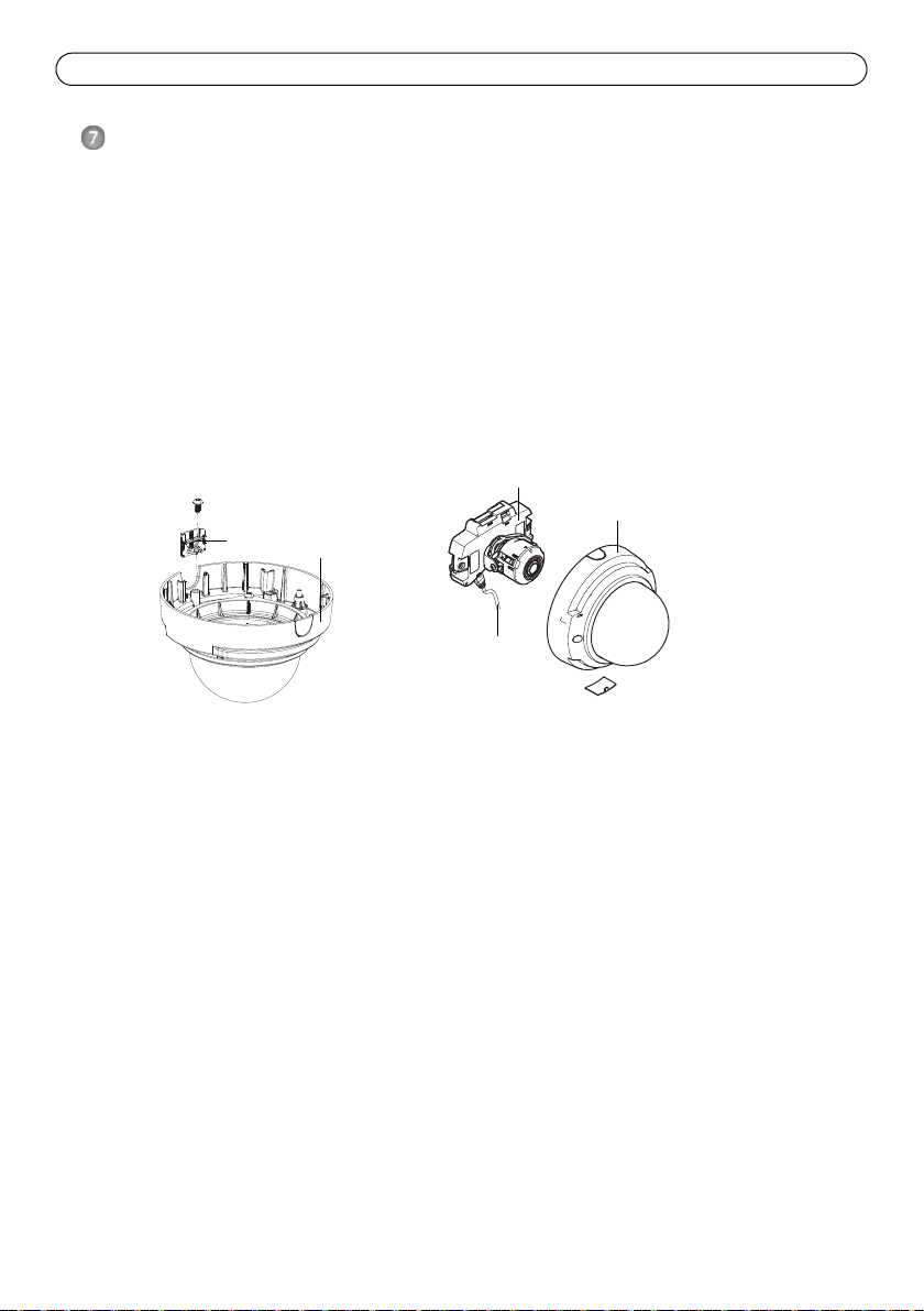
Page 14 AXIS P33 Network Camera Installation Guide
Side lid
Dome cover
Camera unit
Network cable
Dome cover
Complete the installation
1. If the cables are routed along the wall, remove the side lid from the camera’s dome cover.
2. Rotate the black protective shield inside the dome casing to match the camera’s position.
3. Clean the dome with a dry soft cloth to remove dust and finger prints and use a blower to
remove dust from the lens.
4. Mount the dome casing using the supplied tamper-proof screws and screw driver. Now that the
dome is in place, check that the camera is properly focused.
The installation is now complete.
AXIS P33 Network Camera Installation Guide Page 15
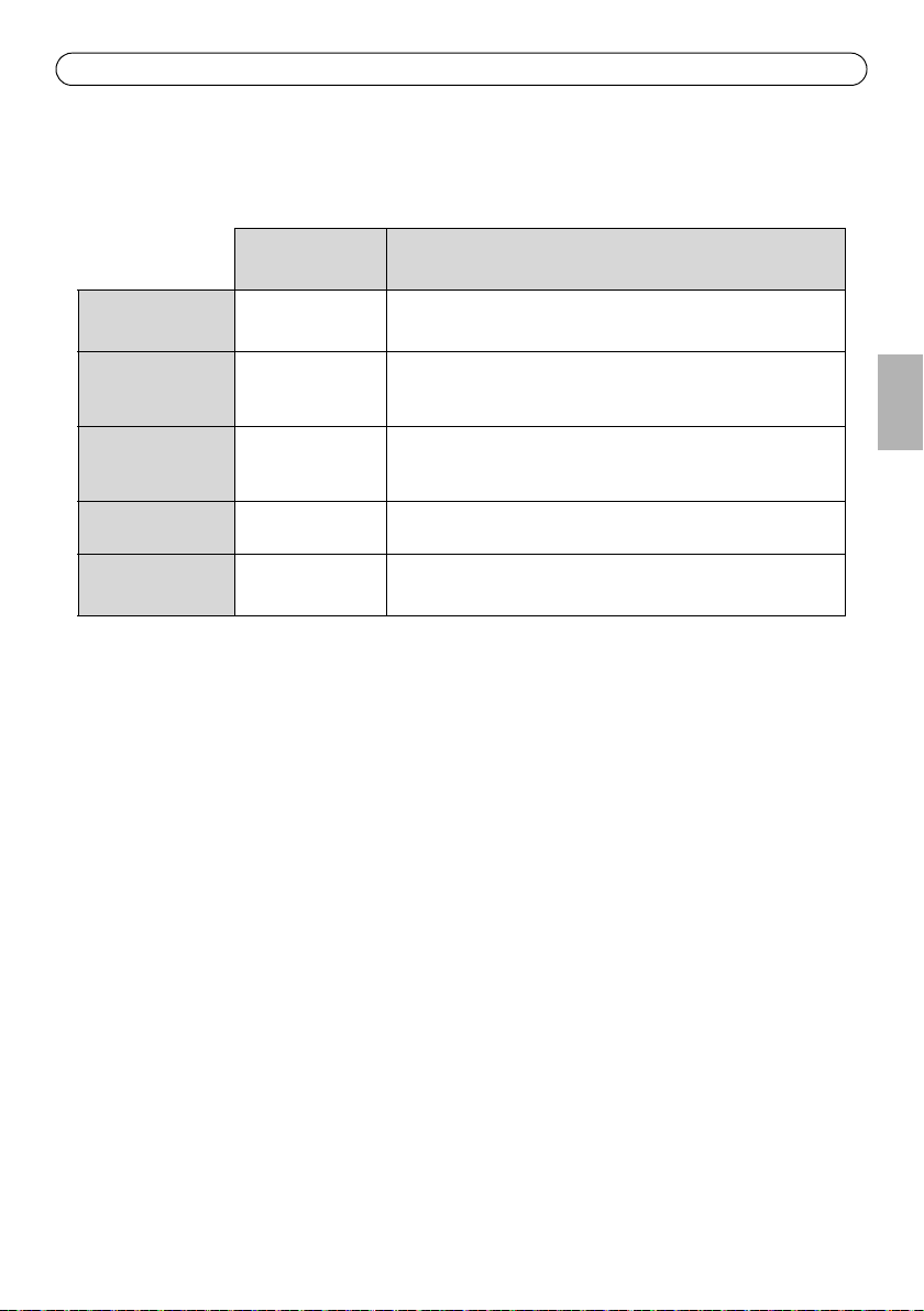
Other methods of setting the IP address
The table below shows the other methods available for setting or discovering the IP address. All
methods are enabled by default, and all can be disabled.
UPnP™
Bonjour
AXIS Dynamic DNS
Service
ARP/Ping
View DHCP server
admin pages
Use in operating
system
Windows When enabled on your computer, the camera is automatically
MAC OSX
(10.4 or later)
All A free service from Axis that allows you to quickly and simply
All See below. The command must be issued within 2 minutes of
All To view the admin pages for the network DHCP server, see the
Notes
detected and added to “My Network Places.”
Applicable to browsers with support for Bonjour. Navigate to the
Bonjour bookmark in your browser (e.g. Safari) and click on the
link to access the camera’s web pages.
install your camera. Requires an Internet connection with no
HTTP proxy. See www.axiscam.net for more information.
connecting power to the camera.
server’s own documentation.
AXIS Video Hosting System (AVHS)
The camera can also be connected to an AVHS service for hosted video. If you have subscribed to an
AVHS service, follow the instructions in the Service Provider’s Installation Guide. For more
information and help to find a local AVHS Service Provider, go to www.axis.com/hosting
The camera owner authentication key is supplied with this product. The key is associated with the
camera’s unique serial number (S/N) as shown on the top of the label.
Save the key for future reference.
Note:
ENGLISH

Page 16 AXIS P33 Network Camera Installation Guide
Set the IP address with ARP/Ping
1. Acquire a free static IP address on the same network segment your computer is connected to.
2. Locate the serial number (S/N) on the camera’s label.
3. Open a command prompt on your computer and enter the following commands:
Windows syntax Windows example
arp -s <IP Address> <Serial Number>
ping -l 408 -t <IP Address>
UNIX/Linux/Mac syntax UNIX/Linux/Mac example
arp -s <IP Address> <Serial Number> temp
ping -s 408 <IP Address>
4. Check that the network cable is connected to the network camera and then start/restart the
network camera, by disconnecting and reconnecting power. If PoE is used, start/restart the
network camera by disconnecting and then reconnecting the network cable.
5. Close the command prompt when you see ‘Reply from 192.168.0.125:...’ or similar.
6. In your browser, type in http://<IP address> in the Location/Address field and press Enter on
your keyboard.
Notes:
• To open a command prompt in Windows: from the Start menu, select Run... and type cmd. Click OK.
• To use the ARP command on a Mac OS X, use the Terminal utility in Application > Utilities.
arp -s 192.168.0.125 00-40-8c-18-10-00
ping -l 408 -t 192.168.0.125
arp -s 192.168.0.125 00:40:8c:18:10:00 temp
ping -s 408 192.168.0.125

AXIS P33 Network Camera Installation Guide Page 17
Pin1
Pin2
Pin3
Pin4
Unit connectors
Note: AXIS P3353 and AXIS P3354 do not support audio or I/O.
Network connector - RJ-45 Ethernet connector. Supports Power over Ethernet.
Due to local regulations or environmental and electrical conditions in which the product is to be
used, a shielded network cable (STP) may be appropriate or required. Network cables that are
routed in outdoor environments or similar shall be shielded (STP) and intended for their specific
use. Make sure that the network switch is properly grounded. See Electromagnetic Compatibility
(EMC) for regulatory requirements.
Audio in - 3.5mm input for a mono microphone, or a line-in mono signal (left channel is used from
a stereo signal).
Audio out - Audio output (line level) that can be connected to a public address (PA) system or an
active speaker with a built-in amplifier. A pair of headphones can also be attached. A stereo
connector must be used for the audio out.
SDHC memory card slot - The SD memory card can be used for local recording with removable
storage.
I/O terminal connector - Used in applications for e.g. motion detection,
event triggering, time lapse recording and alarm notifications. In addition to
an auxiliary power and a GND pin, it provides the interface to:
• 1 transistor output - For connecting external devices such as
relays and LEDs. Connected devices can be activated by the
VAPIX® Application Programming Interface (API), by the output buttons on the Live
View page or by an Action Rule. The output will show as active (shown under System
Options > Ports & Devices) if the alarm device is activated.
• 1 digital input - An alarm input for connecting devices that can toggle between an
open and closed circuit, for example: PIRs, door/window contacts, and glass break
detectors. When a signal is received the state changes and the input becomes active
(shown under System Options > Ports & Devices).
ENGLISH
Function Pin Notes Specifications
GND 1 Ground
3.3V DC
Power
Digital
Input
Digital
Output
2 Can be used to power auxiliary equipment.
Note: This pin can only
3 Connect to GND to activate, or leave floating (or
unconnected) to deactivate.
4 Uses an open-drain NFET transistor with the
source connected to GND. If used with an
external relay, a diode must be connected in
parallel with the load, for protection against
voltage transients.
be used as power out.
Max. load = 50mA
Min. input= 0 to - 40V DC
Max. input= 0 to + 40V DC
Max. load = 100mA
Max voltage = + 40V DC

Page 18 AXIS P33 Network Camera Installation Guide
LED indicators
LED Color Indication
Network Green Steady for connection to a 100 Mbit/s network. Flashes for network activity.
Amber Steady for connection to 10 Mbit/s network. Flashes for network activity.
Unlit No network connection.
Status Green Steady green for normal operation.
Amber Steady during startup, during reset to factory default or when restoring settings.
Red Slow flash for failed upgrade.
Power Green Normal operation.
Amber Flashes green/amber during firmware upgrade.

AXIS P33 Network Camera Installation Guide Page 19
Resetting to the Factory Default Settings
This will reset all parameters, including the IP address, to the factory default settings:
1. Disconnect power from the camera.
2. Press and hold the Control button and reconnect power (see Hardware overview, on page).
3. Keep the Control button pressed for about 15 seconds until the Status indicator flashes amber.
4. Release the Control button. The process is complete after about 1 minute (when the Status
indicator turns green). The network camera has been reset to the factory default settings. The
default IP address is 192.168.0.90
5. Re-assign the IP address.
6. Refocus the camera.
It is also possible to reset parameters to factory default via the web interface. Go to Setup > System
Options > Maintenance.
Accessing the camera from the Internet
Once installed, your network camera is accessible on your local network (LAN). To access the
camera from the Internet, network routers must be configured to allow incoming traffic, which is
usually done on a specific port
• HTTP port (default port 80) for viewing and configuration
• RTSP port (default port 554) for viewing H.264 video streams
Please refer to the documentation for your router for further instructions. For more information on
this and other topics, visit the Axis Support Web at www.axis.com/techsup
ENGLISH
Further information
The user manual is available from the Axis Web site at www.axis.com.
To learn more about Axis' products and technologies, visit www.axis.com/academy, global learning
center for network video.
Tip!
Visit www.axis.com/techsup to check if there is updated firmware available for your Axis product.
To see the currently installed firmware version, see Setup > About in your web interface.

Mesures de sécurité
Lisez attentivement ce guide d’installation avant d’installer le produit. Conservez le guide d’installation pour une
utilisation ultérieure.
ATTENTION!
• Pour éviter d’endommager le produit Axis, utilisez l’emballage d’origine ou un emballage équivalent pour le
transporter.
• Conservez le produit Axis dans un environnement sec et aéré.
• Évitez d’exposer le produit Axis à des vibrations, des chocs ou une trop forte pression et ne l’installez pas
sur des supports instables, ou encore sur des surfaces ou des murs instables ou vibrants; cela risquerait de
l’endommager.
• Utilisez uniquement des outils à main pour l’installation du produit Axis: l’utilisation d’outils électriques ou
l’usage excessif de la force risquent de l’endommager.
• N’utilisez ni produits chimiques, ni substances caustiques, ni nettoyeurs aérosol. Utilisez un chiffon humide
pour le nettoyage.
• N’utilisez que des accessoires conformes aux caractéristiques techniques du produit. Ceux-ci peuvent être
fournis par Axis ou un fournisseur tiers.
• Utilisez uniquement des pièces de rechange fournies ou recommandées par Axis.
• Ne tentez pas de réparer le produit vous-même, contactez Axis ou votre revendeur Axis pour tout problème
de maintenance.
IMPORTANT!
• Ce produit Axis doit être utilisé conformément aux lois et réglementations locales en vigueur.
• Pour pouvoir être utilisé à l’extérieur, ce produit Axis doit être placé dans un boîtier d’extérieur homologué.
Remplacement des piles
Ce produit Axis nécessite une pile au lithium CR2032 de 3V pour l’alimentation de son horloge en temps réel
interne. Dans des conditions normales d’utilisation, cette pile est censée durer au moins 5ans. Si la pile est
faible, le fonctionnement de l’horloge en temps réel peut être affecté et entraîner sa réinitialisation à chaque
mise sous tension. Un message enregistré apparaît lorsque la pile doit être remplacée. Ne remplacez la pile que
lorsque cela est nécessaire.
Si la pile doit être remplacée, veuillez contacter www.axis.com/techsup pour obtenir de l’aide.
• Le remplacement incorrect de la pile peut entraîner un risque d’explosion.
• Remplacez la pile par une pile identique ou équivalente uniquement, en respectant les recommandations du
fabricant.
• Jetez les piles usagées conformément aux consignes du fabricant.
Nettoyage de la bulle du dôme
• Veillez à ne pas rayer ou endommager la bulle du dôme. Ne nettoyez pas la bulle du dôme si elle semble
propre à l’œil nu et ne frottez jamais sa surface. Un nettoyage excessif peut l’endommager.
• Pour le nettoyage général de la bulle du dôme, il est recommandé d’utiliser un savon ou un détergent
neutre sans solvant, non abrasif, avec de l’eau et un chiffon doux. Rincez abondamment avec de l’eau douce
et tiède. Séchez à l’aide d’un chiffon doux pour éviter les salissures d’eau.
• N’utilisez jamais de détergents forts, d’essence, de benzène ou d’acétone, etc. et évitez toute exposition
directe aux rayons du soleil ou à des températures élevées lors du nettoyage.

Caméra réseau AXIS P33 Guide d’installation Page 21
Guide d’installation de la Caméra réseau AXIS
P3353/P3354/P3363-V/P3364-V
Ce guide d’installation explique comment installer la Caméra réseau AXIS P33 sur votre réseau. Pour
toute autre question concernant l’utilisation du produit, reportez-vous au manuel d’utilisation, que
vous trouverez sur le site www.axis.com.
1.
“Contenu de l’emballage”
“Présentation du matériel”
2.
3.
“Montage de la caméra”
“Attribution d’une adresse IP”
4.
“Configuration du mot de passe”
5.
6.
“Réglage de l’objectif”
“Fin de l’installation”
7.
Remarques :
• Avant de commencer, vérifiez le contenu de l’emballage et assurez-vous que les câbles, les outils
et la documentation nécessaires sont disponibles. Voir
• Cette caméra réseau est conçue pour fonctionner avec un connecteur réseau (PoE). Si vous n’en disposez
pas, utilisez Axis PoE Midspan à 1 port (non fourni).
à la page 21
à la page 22
à la page 23
à la page 24
à la page 29
à la page 30
à la page 27
Contenu de l’emballage
ci-dessous.
FRAN
Ç
AIS
Contenu de l’emballage
Élément Modèles/variantes/remarques
Caméra réseau AXIS P3353, AXIS P3354, AXIS P3363-V
AXIS P3364-V
Bulles de dôme Bulle transparente non fumée
Bulle transparente fumée
Étiquettes 2 étiquettes adhésives portant le numéro de série
Kit de montage Tournevis Resitorx, gabarit de perçage, connecteur de connexion
CD CD du produit de vidéo sur IP AXIS comprenant les outils d’installation ainsi
Documentation imprimée Guide d’installation (le présent document)
Accessoires en option Support de fixation (spécifique à la région)
que d’autres logiciels
Document de garantie Axis
Clé d’authentification AVHS
Consultez le site www.axis.com pour plus d’informations sur les accessoires
disponibles
Page 22 Caméra réseau AXIS P33 Guide d’installation
Connecteur réseau
Voyants lumineux
Connecteur d’E/S
(PoE)
Caméra
Câble réseau
Couvercle du dôme
audio
Entrée
Logement pour carte mémoire SD
Vis murales
Sortie
Caméra
Connecteur de sortie
du ventilateur
Microphone intégré
Bouton de
Caméra : P3363/P3364
audio
commande
Présentation du matériel
Remarque : L’AXIS P3353 et l’AXIS P3354 ne prennent pas en charge les câbles E/S et audio.
Dimensions (H x L x P)
AXIS P3353, AXIS P3354, AXIS P3363-V, AXIS P3364-V = 97 x 148 x 148 mm
Poids
AXIS P3353, AXIS P3354 = 430 g
AXIS P3363-V, AXIS P3364-V = 650 g
Caméra réseau AXIS P33 Guide d’installation Page 23
Conduit métallique (en option, non fourni)
Support de fixation (en option, non fourni)
Câble réseau
Vis M4x8
Vis murales
Câble réseau
Montage de la caméra
Ce produit peut être monté avec les câbles d’alimentation acheminés à travers ou le long du mur.
Ce produit peut également être doté d’un conduit métallique pour protéger le câblage lors d’un
acheminement des câbles le long du mur. Référez-vous à l’illustration suivante.
Montage de la caméra directement sur le mur
1. En vous servant du gabarit de perçage, percez 2 trous dans le mur.
2. Acheminez et branchez le câble réseau.
3. Fixez la caméra au mur à l’aide de vis et de chevilles appropriées.
Installez la caméra au moyen d’un support de fixation (non fourni).
1. En vous servant du gabarit de perçage, percez 2 trous dans le mur.
2. Acheminez tous les câbles à travers le mur et à travers les orifices du support de fixation.
3. Fixez le support de fixation au mur à l’aide de vis et de chevilles appropriées.
4. Branchez le câble réseau.
5. Vous pouvez aussi brancher les câbles E/S et audio. Pour plus d’informations, reportez-vous à la
page 33.
6. Si vous le souhaitez, insérez la carte mémoire SD.
7. Fixez la caméra au support de fixation à l’aide de deux vis appropriées.
Remarque :
• Ces instructions concernent l’installation de la caméra sur un mur. Le support de fixation peut aussi être
utilisé pour monter la caméra réseau à un boîtier de jonction.
• L’AXIS P3353 et l’AXIS P3354 ne prennent pas en charge les câbles E/S et audio.
FRAN
Ç
AIS
Page 24 Caméra réseau AXIS P33 Guide d’installation
Attribution d’une adresse IP
La caméra réseau est conçue pour une utilisation sur un réseau Ethernet et une adresse IP est
nécessaire pour y accéder. Aujourd’hui, la plupart des réseaux comportent un serveur DHCP qui
attribue automatiquement des adresses IP aux dispositifs connectés. Si votre réseau ne possède pas
de serveur DHCP, la caméra réseau utilisera l’adresse IP 192.168.0.90 comme adresse IP par défaut.
Si vous souhaitez définir une adresse IP sous Windows, nous vous recommandons d’utiliser
l’application AXIS IP Utility ou AXIS Camera Management. Ces deux applications gratuites sont
disponibles sur le CD joint à votre produit de vidéo sur IP AXIS. Vous pouvez également les
télécharger à partir du site www.axis.com/techsup.
Choisissez la méthode qui vous convient le mieux, selon le nombre de caméras à installer.
Méthode Recommandée pour Système
d’exploitation
AXIS IP Utility
Voir page 25
Logiciel AXIS Camera
Management
Voir page 26
Une seule caméra
Petites installations
Plusieurs caméras
Grandes installations
Installation sur un autre
sous-réseau
Windows
Windows 2000
Windows XP Pro
Windows 2003 Server
Windows 2008 Server
Windows Vista
Windows 7
Remarques :
• Si vous n’arrivez pas à configurer l’adresse IP, vérifiez qu’aucun pare-feu ne bloque l’opération.
• Pour connaître les autres méthodes de configuration ou de détection de l’adresse IP de la caméra réseau
sous d’autres systèmes d’exploitation, reportez-vous à la page 31.
Caméra réseau AXIS P33 Guide d’installation Page 25
AXIS IP Utility – Une seule caméra/petite installation
AXIS IP Utility détecte et affiche automatiquement les périphériques présents sur votre réseau.
Cette application permet également de définir manuellement une adresse IP statique. AXIS IP Utility
est disponible sur le CD accompagnant votre produit de vidéo sur IP Axis. Vous pouvez également la
télécharger depuis le site www.axis.com/techsup.
Notez que vous devez installer la caméra réseau sur le même segment de réseau (sous-réseau
physique) que l’ordinateur exécutant l’application AXIS IP Utility.
Détection automatique
FRAN
Ç
AIS
1. Vérifiez que la caméra réseau est connectée au réseau et qu’elle est sous tension.
2. Lancez AXIS IP Utility.
3. Lorsque le nom de la caméra apparaît dans la fenêtre, double-cliquez dessus pour ouvrir la page
d’accueil correspondante.
4. Reportez-vous à la page 27 pour savoir comment configurer le mot de passe.
Définir manuellement l’adresse IP (optionnel)
1. Trouvez une adresse IP non utilisée sur le même segment de réseau que celui de votre
ordinateur.
2. Sélectionnez la caméra réseau dans la liste.
3. Cliquez sur le bouton Assign new IP address to the selected device (Attribuer une
nouvelle adresse IP au périphérique sélectionné) et saisissez le numéro de série ainsi que
l’adresse IP de la caméra réseau. Le numéro de série figure sur l’étiquette du produit.
4. Cliquez sur le bouton Assign (Attribuer) et suivez les instructions qui s’affichent à l’écran. La
caméra doit être redémarrée dans les deux minutes qui suivent pour que la nouvelle adresse IP
soit prise en compte.
5. Cliquez sur le bouton Home Page (Page d’accueil) pour accéder aux pages web de la caméra.
6. Reportez-vous à la page 27 pour savoir comment configurer le mot de passe.

Page 26 Caméra réseau AXIS P33 Guide d’installation
AXIS Camera Management – Plusieurs caméras/grandes installations
AXIS Camera Management est capable de détecter automatiquement plusieurs périphériques Axis,
d’afficher leur état de connexion, de gérer les mises à niveau des micrologiciels et de définir les
adresses IP.
Détection automatique
1. Vérifiez que la caméra réseau soit bien connectée au réseau et qu’elle se trouve sous tension.
2. Lancez AXIS Camera Management. Lorsque la caméra apparaît dans la fenêtre, cliquez sur le
lien avec le bouton droit de la souris et sélectionnez Live View Home Page (Page d’accueil –
Vidéo en direct).
3. Reportez-vous à la page 27 pour savoir comment configurer le mot de passe.
Attribution d’une adresse IP à un seul périphérique
1. Sélectionnez la caméra dans l’application
AXIS Camera Management, puis cliquez sur le bouton Assign IP
(Attribuer une adresse IP).
2. Sélectionnez Assign the following IP address (Attribuer
l’adresse IP suivante) et saisissez l’adresse IP, le masque de
sous-réseau ainsi que le routeur par défaut que le périphérique
utilisera.
3. Cliquez sur OK.
Attribution d’adresses IP à plusieurs périphériques
AXIS Camera Management accélère le processus d’attribution d’adresses
IP à plusieurs périphériques en suggérant des adresses IP parmi une
plage spécifiée.
1. Sélectionnez les périphériques à configurer (il peut s’agir de modèles
différents), puis cliquez sur le bouton Assign IP (Attribuer adresses
IP) .
2. Sélectionnez Assign the following IP address range (Attribuer la
plage d’adresses IP suivante) et saisissez la plage d’adresses IP, le masque de sous-réseau ainsi
que le routeur par défaut que les périphériques utiliseront.
3. Cliquez sur le bouton OK.
 Loading...