

Axis AXIS 291 1U Installation Guide

AXIS2911UVideoServerRack
ENGLISH
FRANÇAIS
DEUTSCH
ITALIANO
ESPANÕL
ò
ò
¨
¨
¾
¾
InstallationGuide

LegalConsiderations
Videoandaudiosurveillancecanberegulatedbylawsthat
varyfromcountrytocountry.Checkthelawsinyourlocal
regionbeforeusingthisproductforsurveillancepurposes.
Liability
Everycarehasbeentakeninthepreparationofthis
document.PleaseinformyourlocalAxisofceofany
inaccuraciesoromissions.AxisCommunicationsABcannot
beheldresponsibleforanytechnicalortypographicalerrors
andreservestherighttomakechangestotheproductand
manualswithoutpriornotice.AxisCommunicationsAB
makesnowarrantyofanykindwithregardtothematerial
containedwithinthisdocument,including,butnotlimited
to,theimpliedwarrantiesofmerchantabilityandtnessfor
aparticularpurpose.AxisCommunicationsABshallnot
beliablenorresponsibleforincidentalorconsequential
damagesinconnectionwiththefurnishing,performance
oruseofthismaterial.Thisproductisonlytobeusedfor
itsintendedpurpose.
IntellectualPropertyRights
AxisABhasintellectualpropertyrightsrelatingto
technologyembodiedintheproductdescribedinthis
document.Inparticular ,andwithoutlimitation,these
intellectualpropertyrightsmayincludeoneormoreof
thepatentslistedatwww.axis.com/patent.htmandoneor
moreadditionalpatentsorpendingpatentapplicationsin
theUSandothercountries.
EquipmentModications
Thisequipmentmustbeinstalledandusedin
strictaccordancewiththeinstructionsgiveninthe
userdocumentation.Thisequipmentcontainsno
user-serviceablecomponents.Unauthorizedequipment
changesormodicationswillinvalidateallapplicable
regulatorycerticationsandapprovals.
TrademarkAcknowledgments
AXISCOMMUNICATIONS,AXIS,ETRAX,ARTPECandVAPIX
areregisteredtrademarksortrademarkapplicationsofAxis
ABinvariousjurisdictions.Allothercompanynamesand
productsaretrademarksorregisteredtrademarksoftheir
respectivecompanies.
Apple,Boa,Apache,Bonjour ,Ethernet,InternetExplorer,
Linux,Microsoft,Mozilla,Real,SMPTE,QuickTime,UNIX,
Windows,WindowsVistaandWWWareregistered
trademarksoftherespectiveholders.Javaandall
Java-basedtrademarksandlogosaretrademarksor
registeredtrademarksofOracleand/oritsafliates.
TM
UPnP
isacerticationmarkoftheUPnP
Corporation.
TM
Implementers
RegulatoryInformation
Europe
ThisproductcomplieswiththeapplicableCEmarking
directivesandharmonizedstandards:
•ElectromagneticCompatibility(EMC)Directive
2004/108/EC.SeeElectromagneticCompatibility(EMC)
onpage2.
•LowVoltage(LVD)Directive2006/95/EC.SeeSafety
onpage3.
•RestrictionsofHazardousSubstances(RoHS)Directive
201 1/65/EU.SeeDisposalandRecyclingonpage3.
Acopyoftheoriginaldeclarationofconformitymaybe
obtainedfromAxisCommunicationsAB.SeeContact
Informationonpage3.
ElectromagneticCompatibility(EMC)
Thisequipmenthasbeendesignedandtestedtofulll
applicablestandardsfor:
•Radiofrequencyemissionwheninstalledaccordingto
theinstructionsandusedinitsintendedenvironment.
•Immunitytoelectricalandelectromagneticphenomena
wheninstalledaccordingtotheinstructionsandused
initsintendedenvironment.
USA
Thisequipmenthasbeentestedusingashieldednetwork
cable(STP)andfoundtocomplywiththelimitsfora
ClassBdigitaldevice,pursuanttopart15oftheFCC
Rules.Theselimitsaredesignedtoprovidereasonable
protectionagainstharmfulinterferenceinaresidential
installation.Thisequipmentgenerates,usesandcan
radiateradiofrequencyenergyand,ifnotinstalledand
usedinaccordancewiththeinstructions,maycause
harmfulinterferencetoradiocommunications.However,
thereisnoguaranteethatinterferencewillnotoccurin
aparticularinstallation.Ifthisequipmentdoescause
harmfulinterferencetoradioortelevisionreception,which
canbedeterminedbyturningtheequipmentoffandon,
theuserisencouragedtotrytocorrecttheinterferenceby
oneormoreofthefollowingmeasures:
•Reorientorrelocatethereceivingantenna.
•Increasetheseparationbetweentheequipmentand
receiver.
•Connecttheequipmentintoanoutletonacircuit
differentfromthattowhichthereceiverisconnected.
•Consultthedealeroranexperiencedradio/TV
technicianforhelp.
Theproductshallbeconnectedusingashieldednetwork
cable(STP)thatisproperlygrounded.
Canada
ThisdigitalapparatuscomplieswithCANICES-3(ClassB).
Theproductshallbeconnectedusingashieldednetwork
cable(STP)thatisproperlygrounded.
Cetappareilnumériqueestconformeàlanorme
CANNMB-3(classeB).Leproduitdoitêtreconnectéà
l'aided'uncâbleréseaublindé(STP)quiestcorrectement
misàlaterre.
Europe
ThisdigitalequipmentfulllstherequirementsforRF
emissionaccordingtotheClassBlimitofEN55022.The
productshallbeconnectedusingashieldednetworkcable
(STP)thatisproperlygrounded.
Thisproductfulllstherequirementsforimmunity
accordingtoEN61000-6-1residential,commercialand
light-industrialenvironments.
Thisproductfulllstherequirementsforimmunity
accordingtoEN61000-6-2industrialenvironments.
Thisproductfulllstherequirementsforemission
accordingtoEN61000-6-3residential,commercialand
light-industrialenvironments.
Thisproductfulllstherequirementsforimmunity
accordingtoEN55024ofceandcommercialenvironments
Australia/NewZealand
ThisdigitalequipmentfulllstherequirementsforRF
emissionaccordingtotheClassBlimitofAS/NZSCISPR22.
Theproductshallbeconnectedusingashieldednetwork
cable(STP)thatisproperlygrounded.
Japan
この装置は、クラスB情報技術装置です。この装置
は、家庭環境で使用することを目的としています
が、この装置がラジオやテレビジョン受信機に近
接して使用されると、受信障害を引き起こすこと

があります。取扱説明書に従って正しい取り扱い
をして下さい。本製品は、シールドネットワーク
ケーブル(STP)を使用して接続してください。また
適切に接地してください。
Safety
Thepowersupplyusedwiththisproductshallfulll
therequirementsforSafetyExtraLowVoltage
(SELV)andLimitedPowerSource(LPS)accordingto
IEC/EN/UL60950-1.
DisposalandRecycling
Whenthisproducthasreachedtheendofitsusefullife,
disposeofitaccordingtolocallawsandregulations.For
informationaboutyournearestdesignatedcollectionpoint,
contactyourlocalauthorityresponsibleforwastedisposal.
Inaccordancewithlocallegislation,penaltiesmaybe
applicableforincorrectdisposalofthiswaste.
Europe
Thissymbolmeansthattheproductshallnotbe
disposedoftogetherwithhouseholdorcommercialwaste.
Directive2012/19/EUonwasteelectricalandelectronic
equipment(WEEE)isapplicableintheEuropeanUnion
memberstates.Topreventpotentialharmtohumanhealth
andtheenvironment,theproductmustbedisposedofin
anapprovedandenvironmentallysaferecyclingprocess.
Forinformationaboutyournearestdesignatedcollection
point,contactyourlocalauthorityresponsibleforwaste
disposal.Businessesshouldcontacttheproductsupplierfor
informationabouthowtodisposeofthisproductcorrectly.
Thisproductcomplieswiththerequirementsof
Directive2011/65/EUontherestrictionoftheuseof
certainhazardoussubstancesinelectricalandelectronic
equipment(RoHS).
China
Thisproductcomplieswiththerequirementsofthe
legislativeactAdministrationontheControlofPollution
CausedbyElectronicInformationProducts(ACPEIP).
ContactInformation
AxisCommunicationsAB
Emdalavägen14
22369Lund
Sweden
Tel:+46462721800
Fax:+4646136130
www.axis.com
Support
Shouldyourequireanytechnicalassistance,pleasecontact
yourAxisreseller.Ifyourquestionscannotbeanswered
immediately,yourresellerwillforwardyourqueriesthrough
theappropriatechannelstoensurearapidresponse.Ifyou
areconnectedtotheInternet,youcan:
•downloaduserdocumentationandsoftwareupdates
•ndanswerstoresolvedproblemsintheFAQdatabase.
Searchbyproduct,category,orphrase
•reportproblemstoAxissupportstaffbylogginginto
yourprivatesupportarea
•chatwithAxissupportstaff
•visitAxisSupportatwww.axis.com/techsup/
LearnMore!
VisitAxislearningcenterwww.axis.com/academy/for
usefultrainings,webinars,tutorialsandguides.


AXIS2911UVideoServerRack
ENGLISH
SafetyInformation
ReadthroughthisInstallationGuidecarefullybeforeinstallingtheproduct.KeeptheInstallation
Guideforfuturereference.
HazardLevels
DANGER
WARNING
CAUTION
NO
TICE
NO NO
TICE TICE
Indicatesahazardoussituationwhich,ifnotavoided,willresultin
deathorseriousinjury.
Indicatesahazardoussituationwhich,ifnotavoided,couldresult
indeathorseriousinjury.
Indicatesahazardoussituationwhich,ifnotavoided,couldresult
inminorormoderateinjury.
Indicatesasituationwhich,ifnotavoided,couldresultindamage
toproperty.
OtherMessageLevels
ImportantIndicatessignicantinformationwhichisessentialfortheproduct
NoteIndicatesusefulinformationwhichhelpsingettingthemostout
tofunctioncorrectly.
oftheproduct.
5

AXIS2911UVideoServerRack
SafetyInstructions
WARNING
•TheAxisproductshallbeinstalledbyatrainedprofessional.
NO
TICE
NO NO
TICE TICE
•TheAxisproductshallbeusedincompliancewithlocallawsandregulations.
•TousetheAxisproductoutdoors,orinsimilarenvironments,itshallbeinstalledinan
approvedoutdoorhousing.
•StoretheAxisproductinadryandventilatedenvironment.
•AvoidexposingtheAxisproducttoshocksorheavypressure.
•Donotinstalltheproductonunstablebrackets,surfacesorwalls.
•UseonlyapplicabletoolswheninstallingtheAxisproduct.Usingexcessiveforcewith
powertoolscouldcausedamagetotheproduct.
•Useonlyaccessoriesthatcomplywithtechnicalspecicationoftheproduct.Thesecanbe
providedbyAxisorathirdparty.
•UseonlysparepartsprovidedbyorrecommendedbyAxis.
•Donotattempttorepairtheproductbyyourself.ContactAxissupportoryourAxis
resellerforservicematters.
Transportation
NO
TICE
NO NO
TICE TICE
•WhentransportingtheAxisproduct,usetheoriginalpackagingorequivalenttoprevent
damagetotheproduct.
6

AXIS2911UVideoServerRack
1 2 3 4 5 6
ENGLISH
InstallationGuide
ThisInstallationGuideprovidesinstructionsforinstallingAXIS2911UVideoServerRackwhichcan
holduptothreeAxisbladevideoservers.ToinstalltheAxisvideoserveronthenetwork,please
seethevideoserver’sowninstallationguideonwww.axis.com
InstallationSteps
1.Makesurethepackagecontents,toolsandothermaterialsnecessaryfortheinstallation
areinorder.Seepage7.
2.Studythehardwareoverview.Seepage7.
3.Studythespecications.Seepage9.
4.Installthehardware.Seepage12.
PackageContents
•AXIS2911UVideoServerRack
•Frontpanelcover1U(x2)
•ACpowercord,seepage9
•Mountingkit
-Rubberfoot(x4)forplacementonatsurfaces
-Mountingbracket(leftside)
-Mountingbracket(rightside)
-M3x8screwsforattachmentofsidebrackets
-M6x20screwsformountingAXISVideoServerRackinequipmentrack
-Terminalconnectorblock,12–pin,green
•Printedmaterials
-InstallationGuide(thisdocument)
HardwareOverview
1
Powerconnector
7
AXIS2911UVideoServerRack
2
I/OTerminalConnector3
3
I/OTerminalConnector2
4
I/OTerminalConnector1
5
PowerandNetworkLEDs
6
NetworkConnector
LEDIndicators
10/100LED
Red
Green
1000LEDIndication
Green
PowerLEDIndication
Green
Indication
Flashesforconnectiontoa10Mbit/snetwork.
Flashesforconnectiontoa100Mbit/snetwork.
Flashesforconnectiontoa1Gbit/snetwork.
Normaloperation.
ConnectorsandButtons
Forspecicationsandoperatingconditions,seepage9.
NetworkConnector
RJ45Ethernetconnector.
I/OConnector
Usewithexternaldevicesincombinationwith,forexample,tamperingalarms,motiondetection,
eventtriggering,timelapserecordingandalarmnotications.Inadditiontothe0VDCreference
pointandpower(DCoutput),theI/Oconnectorprovidestheinterfaceto:
•Digitaloutput–ForconnectingexternaldevicessuchasrelaysandLEDs.Connected
devicescanbeactivatedbytheVAPIX®ApplicationProgrammingInterface,output
buttonsontheLiveViewpageorbyanActionRule.Theoutputwillshowasactive
(shownunderSystemOptions>Ports&Devices)ifthealarmdeviceisactivated.
•Digitalinput–Analarminputforconnectingdevicesthatcantogglebetweenanopen
andclosedcircuit,forexample:PIRs,door/windowcontacts,glassbreakdetectors,
etc.Whenasignalisreceivedthestatechangesandtheinputbecomesactive(shown
underSystemOptions>Ports&Devices).
8

AXIS2911UVideoServerRack
321 4 5 6 7
ENGLISH
RS485/RS422Connector
TwoterminalblocksforRS485/RS422serialinterfaceusedtocontrolauxiliaryequipmentsuch
asPTZdevices.
Specications
OperatingConditions
TheAxisproductisintendedforindooruse.
ProductTemperatureHumidity
AXIS2911U0°Cto45°C
(32°Fto1 13°F)
PowerSpecications
NO
TICE
NO NO
TICE TICE
Usealimitedpowersource(LPS)witheitheraratedoutputpowerlimitedto≤100W
oraratedoutputcurrentlimitedto≤5A.
20-80%RH(non-condensing)
ProductInputVoltage
AXIS2911U100–240VAC
50–60Hz
InputCurrentPowerConsumption
1.9A
With3AXIS243Q:max.80W
Connectors
PowerConnector
ACconnectorforpowerinput.
Powercordplugvariants:
1
Europe
9
AXIS2911UVideoServerRack
2
UK
3
US,Canada,Japan
4
Australia
5
Switzerland
6
Denmark
7
SouthKorea
PinAssignmentsforI/OConnector-AXISP72Blades
PinFunctionDescription
1
+12Vout,100mA
2
GND
3
4
5
6
7–10
11
12
CongurableI/O1
CongurableI/O2
CongurableI/O3
CongurableI/O4
RS485A
RS485B
Digitalinput-Connectto
GNDtoactivate,orleave
oating(orunconnected)to
deactivate.
Digitaloutput-Usesan
opendrainNFETtransistorwith
thesourceconnectedtoGND.
Ifusedwithanexternalrelay,
adiodemustbeconnected
inparallelwiththeload,for
protectionagainstvoltage
transients.
Notused
Ahalf-duplexRS485interfaceforcontrollingauxiliary
equipmente.g.PTZdevices.
Mininput=0VDC
Maxinput=+40VDC
Maxload=100mA
Maxvoltageapplied=+40V
DC
PinAssignmentsforI/OConnector-AXISQ7414Blade
PinFunctionDescription
1
+12Vout,100mA
2
GND
10

AXIS2911UVideoServerRack
ENGLISH
3
Channel1,Congurable
I/O1
4
Channel2,Congurable
I/O1
5
Channel3,Congurable
I/O1
6
Channel4,Congurable
I/O1
7
Channel1,Congurable
I/O2
8
Channel2,Congurable
I/O2
9
Channel3,Congurable
I/O2
10
Channel4,Congurable
I/O2
11
RS485A
12
RS485B
Digitalinput-ConnecttoGND
toactivate,orleaveoating(or
unconnected)todeactivate.
Digitaloutput-Usesanopen
drainNFETtransistorwiththe
sourceconnectedtoGND.Ifused
withanexternalrelay,adiode
mustbeconnectedinparallel
withtheload,forprotection
againstvoltagetransients.
Ahalf-duplexRS485interfaceforcontrollingauxiliary
equipmentsuchasPTZdevices.
Mininput=–40VDC
Maxinput=+40VDC
Maxload=100mA
Maxvoltage=+40VDC
(tothetransistor)
PinAssignmentsforI/OConnector-AXISQ7406andAXISQ7436Blades
PinFunctionDescription
1
+12Vout,100mA
2
GND
3
Channel1,Congurable
I/O1
4
Channel2,Congurable
I/O1
5
Channel3,Congurable
I/O1
6
Channel4,Congurable
I/O1
7
Channel5,Congurable
I/O1
Digitalinput-ConnecttoGND
toactivate,orleaveoating(or
unconnected)todeactivate.
Digitaloutput-Usesanopen
drainNFETtransistorwiththe
sourceconnectedtoGND.Ifused
withanexternalrelay,adiode
mustbeconnectedinparallel
withtheload,forprotection
againstvoltagetransients.
Mininput=–40VDC
Maxinput=+40VDC
Maxload=100mA
Maxvoltage=+40VDC
(tothetransistor)
11

AXIS2911UVideoServerRack
8
Channel6,Congurable
I/O1
9
Channel1,Congurable
I/O2
10
Channel2,Congurable
I/O2
11
RS485A
12
RS485B
Ahalf-duplexRS485interfaceforcontrollingauxiliary
equipmentsuchasPTZdevices.
InstalltheHardware
NO
TICE
NO NO
TICE TICE
TheAXIS291VideoServerRackisdesignedforusewithAxisBladeVideoServersonly.
ThelocationtheAXIS2911UVideoServerRackisusedinmustmeetthefollowingrequirements:
•Thepowersourcemustbelocatedwithin1.8meters
•Theremustbeaminimumof50mmfreespaceoneachside,toensureadequate
ventilation
•Noexcessivedust
Performthehardwareinstallationinthefollowingorder:
1.PlaceonaFlatSurface
or
Installina19"EquipmentRack
2.InstallBladeVideoServers
3.ConnectI/OTerminalConnector
4.ConnectPower
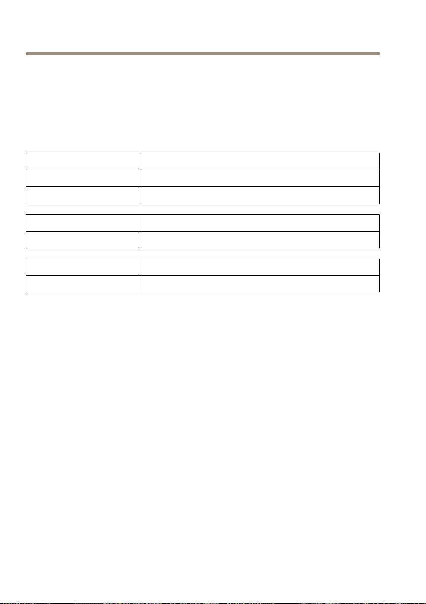
PlaceonaFlatSurface
Note
TheAXISVideoServerRackincludingcablesweighsupto6kg.Checkthatthesurface
cansupportthisweight.
1.Attachthefourrubberfeetonthebottomoftheunit.
2.Placetheunitonaatsurface,forexampleashelforatable.
12
AXIS2911UVideoServerRack
1
1
1
1
ENGLISH
1
Rubberfeet
Installina19"EquipmentRack
NO
TICE
NO NO
TICE TICE
•Themountingbracketsarenotdesignedtosupportmorethanoneunit,neverstack
otherunitsdirectlyontop.
•Eachunitintherackmustbesecuredwithappropriatebrackets.
•Placetheheaviestunitsatthebottomoftherack.
Requirements:
•Pozidrivscrewdriver#1
•Pozidrivscrewdriver#3
•Therackmustbebracedandboltedtotheoor.
•TheAXISVideoServerRackmustbegroundedtothesamegroundastheequipmentrack.
AttachtheBrackets
13
AXIS2911UVideoServerRack
21
1
2
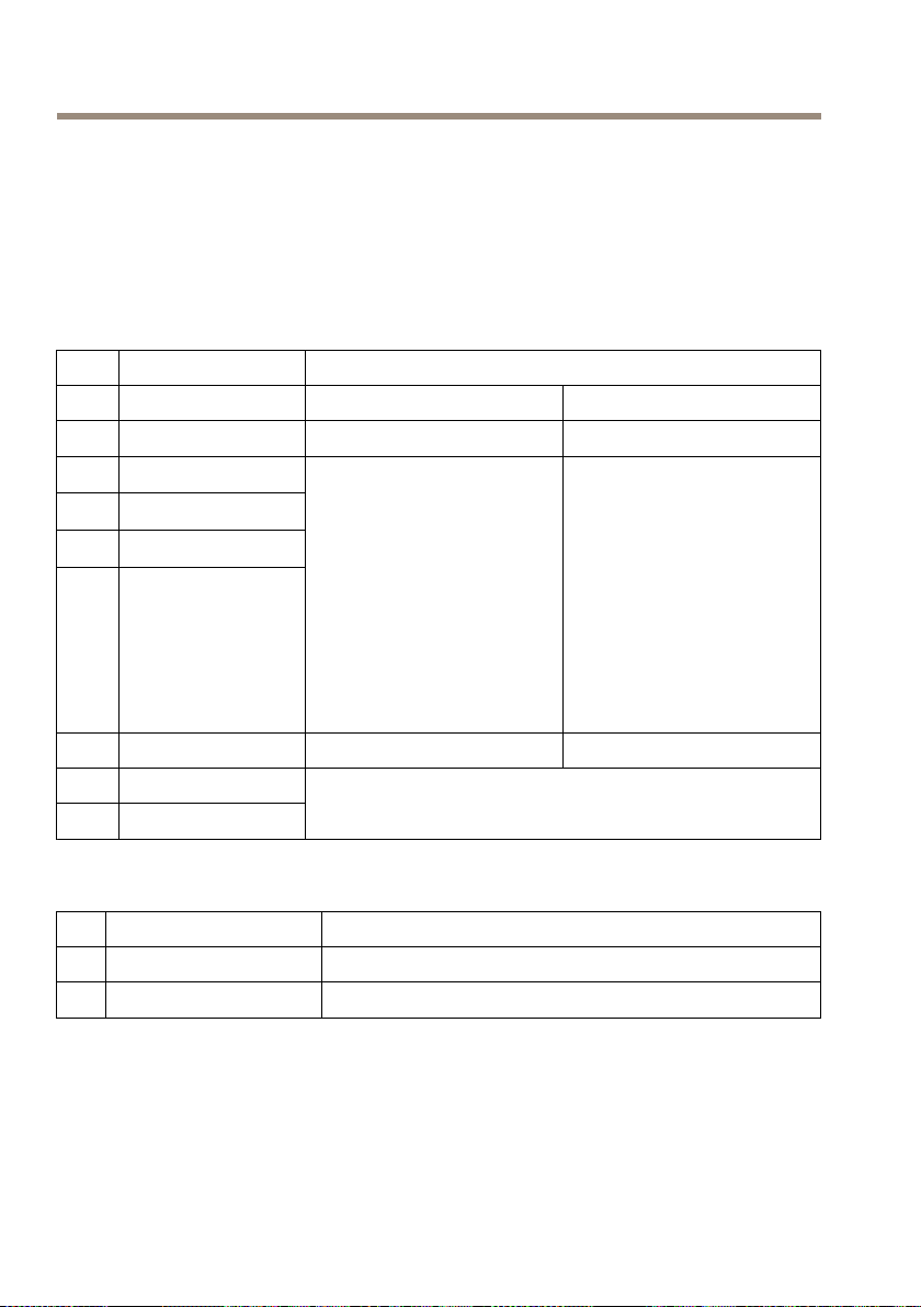
1.Identifytheleftsidemountingbracketandtherightsidemountingbracketbythelabel
oneachbracket.
1
Leftsidemountingbracket
2
Rightsidemountingbracket
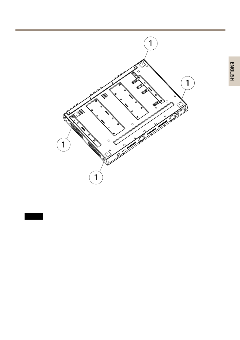
2.Removeanddiscardthescrewfromeachsideoftheunit.
3.Usingtherecessedscrews,fastentheleftsidemountingbracketandtherightside
mountingbrackettothesidesoftheunit.Donotusethescrewthatwasremoved
instep1.
1
Screw
14
AXIS2911UVideoServerRack
3
ENGLISH
2
Recessedscrews(M3x8)
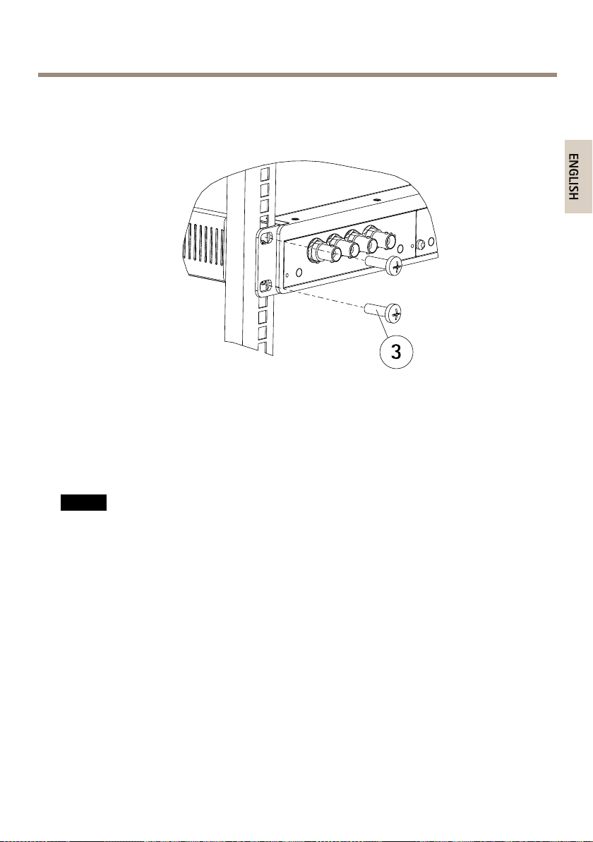
4.SlidetheAXISVideoServerRackintotheequipmentrackandattachthescrews.
3
Screws(M6x20)
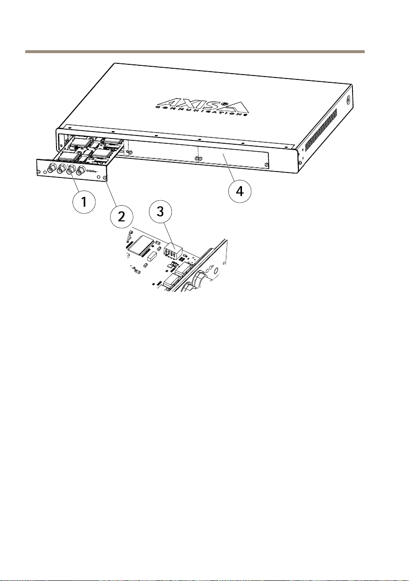
InstallBladeVideoServers
TheAXISVideoServerRackcanaccommodatethreeAxisbladevideoservers.Theslotsforthese
arenumbered1-3fromlefttoright,asseenfromthefront.TheI/Oconnectorsforeachsloton
therearpanelarealsonumbered.
NO
TICE
NO NO
TICE TICE
LeavinganemptyslotontheAXISVideoServerRackopenisnotpermitted.Frontpanel
coversmustbeusedonallemptyslots.
1.Removeafrontpanelcoverfromtheslotinwhichthevideoserverwillbemounted.This
isdonebylooseningthescrewoneachsideofthecover.
2.Usetheguidesasanaidtoslidethevideoserverintoplace.Thedipswitchforsetting
thelineterminationshouldbevisibleonthetopedge.
3.Usethescrewsfromthefrontpanelcovertoattachthevideoserver.
15
AXIS2911UVideoServerRack
1
2
3
4
1
Bladevideoserver
2
Screw
3
Dipswitch
4
Frontpanelcover
ConnectI/OTerminalConnector
Forcompatiblereplacementconnectors,contacthttp://www.phoenixcontact.com,quoting:MC1.5/
12-ST-3.81(artno1803675).
Toconnectinput/outputdevicestotheI/Oterminalconnector,dothefollowing:
Dependingonwhichbladeisusedintheinstallation,seepage10orpage11.
1.Referringtothetablesabove,loosenthecorrespondingscrewontopofthepinon
thegreenconnectorblock.
2.Pushthecableintotheconnectorblockandsecureitbyfasteningthescrew.
3.Oncealldevicesareconnected,pushtheconnectorblockintotheterminalconnector
ontherearpanelofthevideoserverrack.
16

AXIS2911UVideoServerRack
ENGLISH
ConnectPower
NO
TICE
NO NO
TICE TICE
•Topreventtheriskofelectricalshockwhenincontactwiththeunitcasing,onlyearthed/
groundedpowercordsshouldbeusedtopowertheAXISVideoServerRack.
•Protectionagainstovercurrent,shortcircuitsandearthfaultsshouldbeprovidedinthe
buildinginstallation.
•TheAXISVideoServerRackisintendedforindooruseonly,andonlyforTNandITpower
systems.
•IfaforeignobjectisaccidentlydroppedintotheVideoServerRack,alwaysdisconnect
powerbeforeattemptingtoremovetheobject.
TheAXISVideoServerRackhasnoOn/Offswitchorbuttonandwillpowerupassoonasthe
powercordisconnected.Detachingthecordistheonlywaytoremovepower,soitisimportant
tolocatetheunitsothatthepowercordiseasilyaccessible.PleaseensurethatthecorrectAC
powercordforyourcountryisused,seepage9.
FurtherInformation
VisitAxislearningcenterwww.axis.com/academyforusefultrainings,webinars,tutorialsand
guides.
WarrantyInformation
ForinformationaboutAxis’productwarrantyandtheretorelatedinformation,see
www.axis.com/warranty/
17

18
AXIS2911UVideoServerRack
FRANÇAIS
Informationssurlasécurité
Lisezattentivementceguided'installationavantd'installerl'appareil.Conservezleguide
d'installationpourtouteréférenceultérieure.
Niveauxderisques
DANGER
AVERTISSEMENT
ATTENTION
VIS
A AAVIS VIS
Indiqueunesituationdangereusequi,siellen'estpasévitée,
entraîneraledécèsoudesblessuresgraves.
Indiqueunesituationdangereusequi,siellen'estpasévitée,
pourraitentraînerledécèsoudesblessuresgraves.
Indiqueunesituationdangereusequi,siellen'estpasévitée,
pourraitentraînerdesblessureslégèresoumodérées.
Indiqueunesituationqui,siellen'estpasévitée,pourrait
endommagerl'appareil.
Autresniveauxdemessage
ImportantIndiquelesinformationsimportantes,nécessairespourassurerle
NoteIndiquelesinformationsutilesquipermettrontd'obtenirle
bonfonctionnementdel'appareil.
fonctionnementoptimaldel'appareil.
19

AXIS2911UVideoServerRack
Consignesdesécurité
AVERTISSEMENT
•LeproduitAxisdoitêtreinstalléparunprofessionnelhabilité.
VIS
A AAVIS VIS
•LeproduitAxisdoitêtreutiliséconformémentauxloisetrèglementationslocalesen
vigueur.
•PourpouvoirutiliserleproduitAxisàl'extérieur,oudansdesenvironnementssimilaires,il
doitêtreinstallédansunboîtierd'extérieurhomologué.
•ConserverceproduitAxisdansunenvironnementsecetventilé.
•NepasexposerceproduitAxisauxchocsouauxfortespressions.
•Nepasinstallerceproduitsurdessupports,surfacesoumursinstables.
•Utiliseruniquementdesoutilsrecommandéspourl'installationdel'appareilAxis.
L'applicationd'uneforceexcessivesurl'appareilavecdesoutilspuissantspourrait
l'endommager.
•Utiliseruniquementdesaccessoiresconformesauxcaractéristiquestechniquesduproduit.
IlspeuventêtrefournisparAxisouuntiers.
•UtiliseruniquementlespiècesderechangefourniesourecommandéesparAxis.
•Nepasessayerderéparerceproduitparvous-même.Contacterl'assistancetechnique
d'AxisouvotrerevendeurAxispourdesproblèmesliésàl'entretien.
Transport
VIS
A AAVIS VIS
•LorsdutransportduproduitAxis,utilisezl'emballaged'origineouunéquivalentpour
éviterd'endommagerleproduit.
20

AXIS2911UVideoServerRack
FRANÇAIS
Guided’installation
Ceguided'installationfournitdesinstructionsd'installationpourlerackdeserveurvidéoAXIS291
1Uquipeutaccueillirjusqu'à3serveursvidéoàlamesAxis.Poursavoircommentinstallerleserveur
vidéoAxissurleréseau,veuillezvousreporterauguided’installationduserveursurwww.axis.com.
Procéduresd’installation
1.Assurez-vousquelesoutilsetautresmatérielsnécessairesàl'installationsontinclus
dansl'emballage.Cf.page21.
2.Consultezladescriptiondumatériel.Cf.page22.
3.Étudiezlescaractéristiques.Cf.page9.
4.Installezlematériel.Cf.page27.
Contenudel’emballage
•RackdeserveurvidéoAXIS2911U
•Couvercledepanneauavant1U(x2)
•Cordond’alimentationCA,voirpage24
•Kitdemontage
-Piedsencaoutchouc(x4)pouruneinstallationsursurfaceplane
-Supportdexation(gauche)
-Supportdexation(droit)
-VisM3x8pourxationdessupportslatéraux
-VisM6x20pourxationdurackdeserveurvidéoAXISdanslerackde
l'équipement
-Blocconnecteurpourterminaux12broches,vert
•Documentsimprimés
-Guided’installation(cedocument)
21

AXIS2911UVideoServerRack
1 2 3 4 5 6
Aperçudumatériel
1
Connecteurd'alimentation
2
Connecteurpourterminauxd'E/S3
3
Connecteurpourterminauxd'E/S2
4
Connecteurpourterminauxd'E/S1
5
Voyantsalimentationetréseau
6
Connecteurréseau
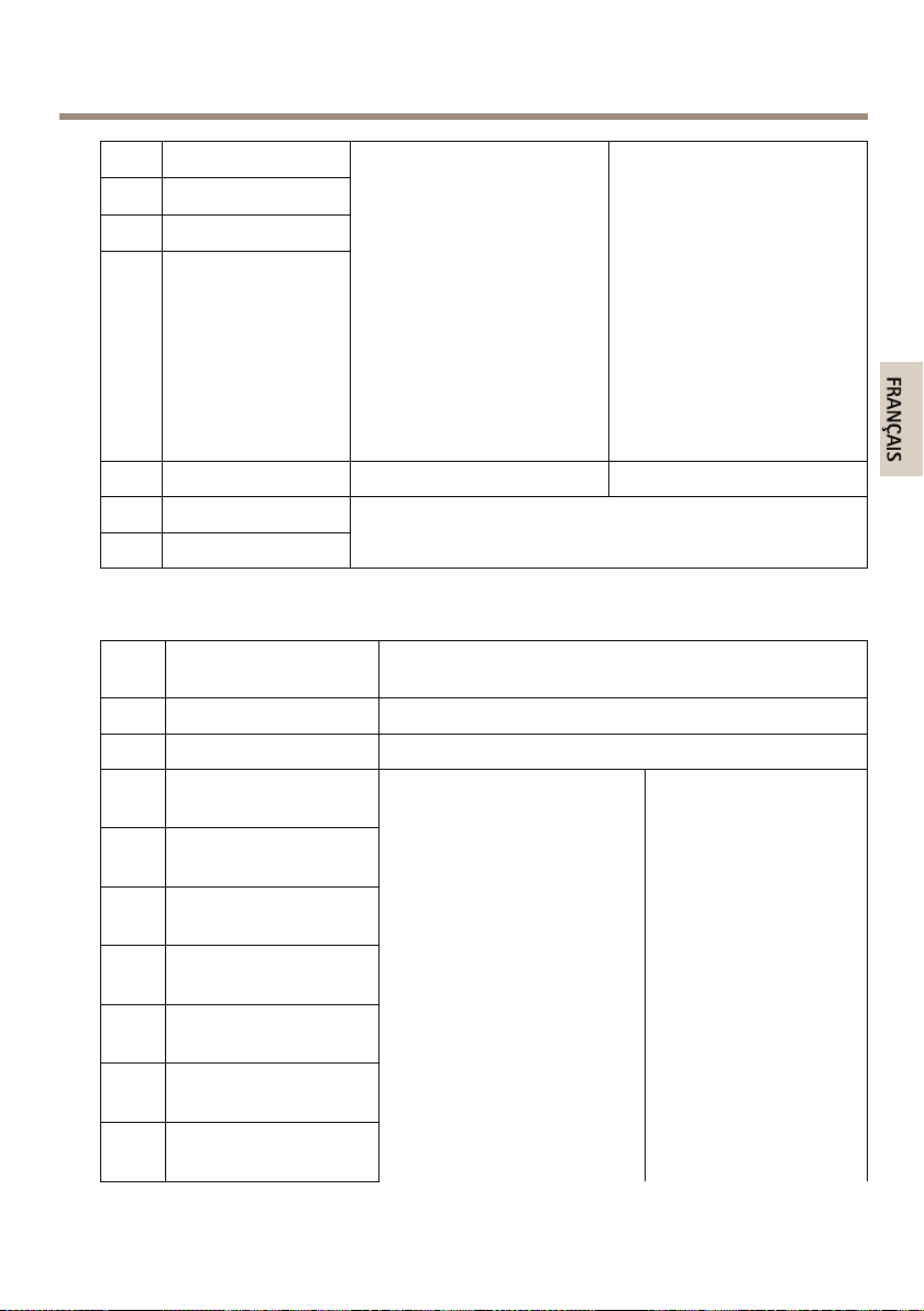
Voyants
Voyant10/100
Rouge
Vert
Voyant1000Indication
Vert
Voyantd'alimentationIndication
VertFonctionnementnormal.
Indication
Clignoteencasdeconnexionàunréseaude10Mbit/s.
Clignoteencasdeconnexionàunréseaude100Mbit/s.
Clignoteencasdeconnexionàunréseaude1Gbit/s.
Connecteursetboutons
Pourlescaractéristiquesetlesconditionsd'utilisation,consultezpage23.
Connecteurréseau
ConnecteurEthernetRJ45.
22
AXIS2911UVideoServerRack
FRANÇAIS
Connecteurd'E/S
Utilisez-leavecdespériphériquesexternesassociésauxapplicationstellesquelesalarmesde
détérioration,ladétectiondemouvement,ledéclenchementd'événements,l'enregistrementà
intervallesetlesnoticationsd'alarme.Enplusdupointderéférence0VCCetdel'alimentation
(sortieCC),leconnecteurd'E/Sfournituneinterfaceauxélémentssuivants:
•Sortienumérique–Permetdeconnecterdesdispositifsexternes,commedesrelais
oudesvoyants.Lesappareilsconnectéspeuventêtreactivésparl'interfacede
programmationVAPIX®,desboutonsdesortiesurlapageLiveView(Vidéoendirect)
ouparunerègled'action.Lasortieestconsidéréecommeétantactive(commeindiqué
dansSystemOptions>Ports&Devices(Optionsdusystème>Portsetdispositifs))si
ledispositifd’alarmeestactivé.
•Entréenumérique–Entréed'alarmeutiliséepourconnecterdesdispositifspouvant
passerd'uncircuitouvertàuncircuitfermé,parexemple:détecteursinfrarougepassifs,
contactsdeporte/fenêtre,détecteursdebrisdeverre,etc.Àlaréceptiond'unsignal,
l'étatchangeetl'entrées'active(sousSystemOptions>Ports&Devices(Optionsdu
système>Portsetdispositifs)).
ConnecteurRS485/RS422
Deuxblocsterminauxà2brochespourl’interfacesérieRS485/RS422utiliséepourcommanderles
équipementsauxiliaires,telsquelesdispositifspanoramique/inclinaison.
Caractéristiquestechniques
Conditionsd'utilisation
LeproduitAxisestuniquementdestinéàuneutilisationenintérieur.
Produit
AXIS2911U0°Cà45°C
TempératureHumidité
(32°Fà113°F)
Humiditérelativede20à80%
(sanscondensation)
Caractéristiquesd'alimentation
VIS
A AAVIS VIS
Utilisezunesourced'alimentationlimitée(LPS)dontlapuissancedesortienominaleest
limitéeà≤100Woudontlecourantdesortienominalestlimitéà≤5A.
23

AXIS2911UVideoServerRack
321 4 5 6 7
Produit
AXIS2911U100-240VCA
Tensiond'entréeCourantd'entréeConsommationélectrique
50–60Hz
Connecteurs
Connecteurd’alimentation
ConnecteurCApourl'alimentation.
Variantesdechedecordond’alimentation:
1
Europe
2
Royaume-Uni
3
États-Unis,Canada,Japon
4
Australie
5
Suisse
6
Danemark
7
CoréeduSud
1,9A
Avec3AXIS243Q:max.80W
Affectationdesbrochesduconnecteurd’E/S-LamesAXISP72
Bro-
FonctionDescription
che
1
Sortie+12V,100mA
2
Terre
24
AXIS2911UVideoServerRack
FRANÇAIS
3
Congurationd’E/S1
4
Congurationd’E/S2
5
Congurationd’E/S3
6
Congurationd’E/S4
7–10
11
RS485A
12
RS485B
Entréenumérique:
connectez-laàlaterre
pourl’activeroulaissez-la
otter(oudéconnectée)pour
ladésactiver.
Sortienumérique:utiliseun
transistorNFETàdrainouvert
aveclasourceconnectéeà
laterre.Encasd’utilisation
avecunrelaisexterne,une
diodedoitêtreconnectéeen
parallèleaveclacharge,pour
assurerlaprotectioncontreles
tensionstransitoires.
Nonutilisé
InterfaceRS485semi-duplexpermettantdecontrôlerun
équipementauxiliaire,parexempledesappareilsPTZ.
Entréeminimale=0VCC
Entréemaximale=+40VCC
Chargemaximale=100mA
Tensionmaximale=+40VCC
Affectationdesbrochesduconnecteurd’E/S-LameAXISQ7414
Bro-
FonctionDescription
che
1
Sortie+12V,100mA
2
Terre
3
4
5
6
7
8
9
Canal1,entrée/sortie
congurable1
Canal2,entrée/sortie
congurable1
Canal3,entrée/sortie
congurable1
Canal4,entrée/sortie
congurable1
Canal1,entrée/sortie
congurable2
Canal2,entrée/sortie
congurable2
Canal3,entrée/sortie
congurable2
Entréenumérique:
connectez-laàlaterrepour
l’activeroulaissez-laotter(ou
déconnectée)pourladésactiver.
Sortienumérique:utiliseun
transistorNFETàdrainouvert
aveclasourceconnectéeàla
terre.Encasd’utilisationavec
unrelaisexterne,unediode
doitêtreconnectéeenparallèle
aveclacharge,pourassurerla
protectioncontrelestensions
transitoires.
Entréemin.=-40VCC
Entréemax.=+40VCC
Chargemaximale=
100mA
Tensionmaximale=
+40VCC
(versletransistor)
25

AXIS2911UVideoServerRack
10
11
12
Canal4,entrée/sortie
congurable2
RS485A
RS485B
InterfaceRS485semi-duplexpermettantdecontrôlerun
équipementauxiliaire,parexempledesappareilsPTZ.
Affectationdesbrochesduconnecteurd’E/S-LamesAXISQ7406etAXIS
Q7436
Bro-
FonctionDescription
che
1
Sortie+12V,100mA
2
Terre
3
4
5
6
7
8
9
10
11
12
Canal1,entrée/sortie
congurable1
Canal2,entrée/sortie
congurable1
Canal3,entrée/sortie
congurable1
Canal4,entrée/sortie
congurable1
Canal5,entrée/sortie
congurable1
Canal6,entrée/sortie
congurable1
Canal1,entrée/sortie
congurable2
Canal2,entrée/sortie
congurable2
RS485A
RS485B
Entréenumérique:
connectez-laàlaterre
pourl’activeroulaissez-la
otter(oudéconnectée)pour
ladésactiver.
Sortienumérique:utiliseun
transistorNFETàdrainouvert
aveclasourceconnectéeà
laterre.Encasd’utilisation
avecunrelaisexterne,une
diodedoitêtreconnectéeen
parallèleaveclacharge,pour
assurerlaprotectioncontreles
tensionstransitoires.
InterfaceRS485semi-duplexpermettantdecontrôlerun
équipementauxiliaire,parexempledesappareilsPTZ.
Entréemin.=-40VCC
Entréemax.=+40VCC
Chargemaximale=
100mA
Tensionmaximale=
+40VCC
(versletransistor)
26
AXIS2911UVideoServerRack
FRANÇAIS
Installationdumatériel
VIS
A AAVIS VIS
LerackdeserveurvidéoAXISestconçupouraccueillirdesserveursvidéoàlamesAxis
uniquement.
LerackdeserveurvidéoAXIS2911Udoitêtreinstalléàunemplacementrépondantauxcritères
suivants:
•Sourced’alimentationàmoinsde1,80mètre.
•Pourassureruneventilationsufsante,50mmd'espacelibredechaquecôté
•Pasdepoussièreexcessive
Procédezàl'installationdumatérieldansl'ordresuivant:
1.Placementsurunesurfaceplane
ou
Installationdansunrack19pouces
2.Installationdeserveursvidéoàlames
3.Branchementduconnecteurpourterminauxd'E/S
4.Branchementdel’alimentation
Placementsurunesurfaceplane
Note
LerackdeserveurvidéoAXISpeutpeserjusqu'à6kg,câblescompris.Assurez-vousquela
surfacesoitsufsammentsolidepoursupportercepoids.
1.Fixezlesquatrepiedsencaoutchoucsurlapartieinférieuredel'appareil.
2.Placezl'appareilsurunesurfaceplane,parexempleuneétagèreouunetable.
27
 Loading...