


DMF Series Solution Feeder
Installation, Operation, & Maintenance Instructions
- Français page 11 -
Installation Procedure
1)Set system feeder on a secure and level base or on the provided wall bracket.
2)If mounting on the wall, the cardboard cut-out on the side of the DMF box may be used to locate the screw holes for the wall bracket.
3)Ensure the wall bracket is level and fastened securely to the wall.
4)HANG AND FILL TANK PRIOR TO MAKING SYSTEM CONNECTION. This helps to ensure that the tank is securely seated on the mounting bracket
Startup Procedure
1)Close isolation valve between feeder and system connection point
2)Fill reservoir, turn valve on feeder to mix/purge and plug in
3)Ensure pump is cycling fluid through reservoir (primed)
4)Simultaneously turn valve to run and open isolation valve to system
Scan the QR code to the left, search for Axiom Industries Ltd. on YouTube, or use the link below to view a list of instructional videos on the DMF series system feeders: https://www.youtube.com/watch?v=tmWsw0clEng&list=UU3IhT 10cEPKmm_S-HlGcbNw
3603 Burron Avenue, Saskatoon, SK S7P 0E4 |
Ph: (306) 651-1815 Fax: (306) 651-2293 |
email: sales@axiomind.com |
website: www.axiomind.com |
DMF150 HYDRONIC SYSTEM FEEDER
INSTALLATION, OPERATION, AND MAINTENANCE INSTRUCTIONS
The system feeder is used to maintain a minimum system pressure within a hydronic heating or cooling system. It should be used to pressurize the system while the system temperature is at its lowest.
Installation Instructions
1.Set system feeder on a secure and level base or on the provided wall bracket. If mounting on the wall, the cardboard cut-out on the side of the DMF box may be used to locate the screw holes for the wall bracket. Ensure the wall bracket is level and fastened securely to the wall. HANG AND FILL
TANK PRIOR TO MAKING SYSTEM CONNECTION.
2.Connect the unit to the system using suitable hydronic piping. Ensure that there is a system isolation valve installed to allow for isolation of the unit. DO NOT INSTALL A CHECK VALVE OR
PRESSURE REGULATOR BETWEEN SOLUTION FEEDER AND SYSTEM.
3.Mount power supply and secure with mounting bracket. Do not power up system feeder until a system connection is made, isolation valve is closed and feeder valve is set to mix.
4.To connect the system feeder to the RIA10-1-SAA alarm panel connect the blue and green wires from the digital pressure controller to terminals 1 and 2 inside the Axiom RIA10-1-SAA alarm panel.
5.Install proper water/glycol mix in the tank to a level above minimum level indication on tank scale. A 30-50% Propylene Glycol mixture is recommended.
6.Close system isolation valve, turn feeder valve to vertical position (mix position).
7.Insert DC plug into the System Feeder first, and then plug power supply into 120v outlet. The red LED in the power supply cord should light up. If it does not, check the power receptacle.
8.Once the pump is primed, turn the feeder valve handle to horizontal position (run position), open system isolation valve and allow pump to pressurize system. If the system pressure is below the cut in pressure setting (approx.16 psi), the pump will start. The system feeder will run until the system is pressurized to approximately 18 psi and shut-off. It may cycle a number of times while system pressure stabilizes and while air is removed from the system.
9.If a higher fill pressure is required (up to 45 psi) the digital pressure controller may be adjusted by pressing the up arrow to increase pressure and the down arrow to decrease pressure. The Pressure cannot be adjusted outside the high pressure (HiAL default = 26 psi) and low pressure (LoAL default = 10 psi) set point. The F2 alarm set points will need to be adjusted before a fill pressure can be set outside these set points. Please see the F2 function in the Adjusting the Digital Pressure Controller section on the following page.
Please note that the digital pressure read out may read differently from another gauge, which may be installed elsewhere in the system. This may be due to gauge calibration or differences in elevation within the system.
The system feeder does not require any scheduled maintenance. Should you wish to test pump operation, turn mix/purge valve to vertical position to start pump. Turning mix/purge valve handle back to the horizontal position will allow the pump to re-pressurize the system and then shut off.
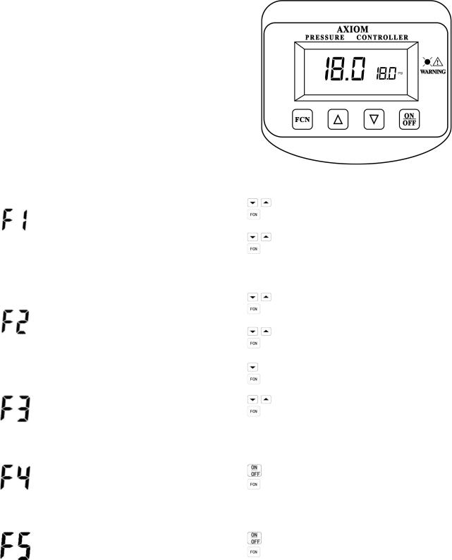
Adjusting the Digital Pressure Controller on the DMF Series Solution Feeders
The pressure controller is factory set to start the pump at 16psi and shut off the pump at 18 psig. It can be field adjusted to a maximum of 45 psig. To quickly adjust the pressure set point, without changing the differential, press the up or down arrows on the front of the pressure controller.
Function Menu
The five functions of the digital pressure controller may be toggled through by pressing the  button. Press and hold the
 button for 3 seconds to enter the function menu shown below. The
  button moves you through the menu while the

 arrow buttons are used to change the settings.
Symbol |
Description |
Operation |
|
|
|
|
|
|
F1-Hi–P (Pump cut-out set point) |
to adjust the pump cut-out set point |
|
|
F1-Lo-P (Pump cut-in set point) |
to lock in setting and move on |
|
|
|
||
Pressure Settings |
Default: |
to adjust the pump cut-in set point |
|
for Pump Operation |
to lock in setting and move on |
||
Hi-P = 18.0 psi. |
|||
|
|
||
|
Low-P = 16.0 psi. |
|
|
|
Min. recommended differential 2psi |
|
|
|
F2-H (HiAL) (high pressure alarm), |
to adjust the high pressure alarm set point |
|
|
Default HiAL = 26 psi |
to lock in setting and move on |
|
|
F2-L (LoAL) (low pressure alarm) |
to adjust the low pressure alarm set point |
|
Pressure Settings for |
Default LoAL = 10 psi |
||
to lock in setting and move on |
|||
the Alarm |
|
||
F2-r NO (normally open contacts) |
|
||
|
to select N/O or N/C |
||
|
NC (normally closed contacts) |
||
|
to lock in setting and move on |
||
|
|
||
|
Sets the maximum pressure to which |
to adjust the MAX pressure |
|
|
the pump Cut-out setting may be set |
to lock in setting and move on |
|
Max Pump Operating |
Default setting = 45 psi |
|
|
Pressure Setting |
|
||
|
|
||
|
|
|
|
|
This can be used to manually test the |
to turn the load relay (pump) on and off |
|
|
load relay (pump) |
||
|
to move on to F5 |
||
|
|
||
Pump Relay Test |
|
|
|
(PTST) |
|
|
|
|
|
|
|
|
This can be used to test the alarm |
to turn the alarm relay on or off |
|
|
relay |
||
|
to go back to normal operating mode |
||
|
|
||
Alarm Relay Test |
|
|
|
(ATST) |
|
|
How to Factory Reset the Digital Pressure Controller
1.Simultaneously press the  and
and  buttons and hold for about 4 seconds.
2.The screen will display 
3.Press the  or
or  button
4.The screen will display 
5.Press the  button
The signal light will then flicker continuously several times before resetting the digital pressure controller
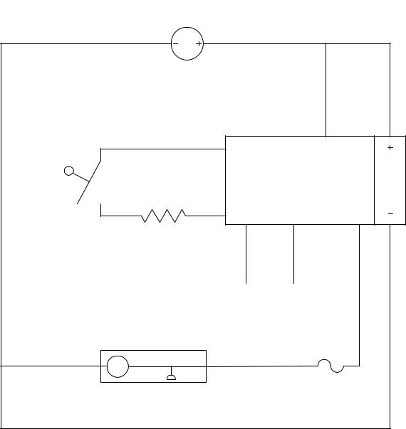
DMF Wiring Diagram
Dry contact (blue and green wire) rating: 5a/125vac 28vdc
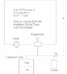
COLD STATIC FILL PRESSURE
The cold static fill pressure (CSFP) in a closed hydronic system has to be high enough to accomplish three things.
1)Overcome the static head (height) between the fill point and the highest point in the system.
2)Provide adequate pressure (minimum 4 psig) at the top of the system for proper air venting.
3)Maintain adequate pressure at the inlet of the system pumps to prevent cavitation.
The formula for calculating the required CSFP to satisfy points 1 & 2 is:
(Static height in feet/2.31) + 4 = CSFP in psig.
As an example, the CSFP for a system with a static height above the fill point of 32 feet would be: (32/2.31) + 4 = 18 psig.
For most closed hydronic systems operating below about 210 F, maintaining the minimum top- of-system pressure at 4 psig will be adequate to prevent pump cavitation even if the pumps are at or near the top of the system as well.
IMPORTANT NOTE – For air-charged diaphragm or bladder tanks, the air charge in the tank must be adjusted to equal the cold static fill pressure before it is connected to the system.
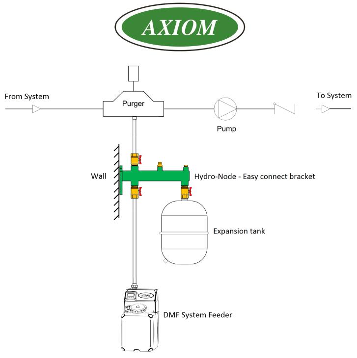
Connection Schematic – DMF Series Hydronic System Feeder
3603 Burron Avenue, Saskatoon, SK S7P 0E4 |
Ph: (306) 651-1815 Fax: (306) 651-2293 |
email: sales@axiomind.com |
website: www.axiomind.com |

|
|
LEGEND |
|
DMF-150 (EXPLODE) |
AXIOM INDUSTRIES |
1 |
PARTS LIST |
16 MAY 2018 |
 Loading...