


Reverse Osmosis
User’s Manual
Model
R1-1140, R1-2140, R1-3140,
R1-4140, R1-5140, R1-6140
R1-6140 Pictured
MKTF - 211 |
07/26/12 |

This Page Intentionally
Left Blank
2
MKTF - 211 |
07/26/12 |

TABLE OF CONTENTS |
|
INTRODUCTION ................................................................................................................................... |
4 |
SAFETY ................................................................................................................................................ |
4 |
FEED WATER AND OPERATION SPECIFICATIONS .................................................................................. |
5 |
REJECTION, RECOVERY AND FLOW RATES............................................................................................ |
5 |
SYSTEM REQUIREMENTS AND OPERATION GUIDELINES....................................................................... |
6 |
MEMBRANE ELEMENTS ....................................................................................................................... |
8 |
R1-1140, R1-2140, R1-3140, R1-4140, R1-5140, R1-6140 ................................................................... |
16 |
SYSTEM IDENTIFICATION ................................................................................................................... |
16 |
|
21 |
|
22 |
|
24 |
|
24 |
|
26 |
|
28 |
|
28 |
REVERSE OSMOSIS TROUBLESHOOTING ............................................................................................ |
29 |
TEMPERATURE CORRECTION FACTORS FOR MEMBRANE................................................................... |
31 |
OPERATION ....................................................................................................................................... |
33 |
DRAWINGS ........................................................................................................................................ |
34 |
3
MKTF - 211 |
07/26/12 |

INTRODUCTION
Your R1-Series system is a duraable piece of equipment which, with proper care, will last for many years. This User’s Manual outlines insttallation, operation, maintenance, and troubleshooting details vital to the sustained performance of your system.
The test results which are included with this User’s Manual indicate your system’s permeate (product) and concentrate (waste) test results.
If your system is altered at the site of operation or if the feed water conditions change, please contact your local dealer or distributor to determine the proper recovery for your applicatioon.
NOTE: IN ORDER TO MAINTTAIN THE MANUFACTURER’S WARRANTY, AN OPERATING LOG MUST BE MAINTAINED AND COPIES WILL NEED TO BE SENT TO YOUR LOCAL DEALER OR DISTRIBUTOR FOR REVIEW.
NOTE: |
USER’S |
MANUAL |
|
The |
this |
manual’s |
|
NOTE: |
. |
CAUTION: INDICATES STATEMENTS THAT ARE USED TO IDEN TIFY CONDITIONS OR PRACTICES THAT COULD RESULT IN EQUIPMENT OR OTHER PROPERTY DAMAGE.
WARNING: INDICATEES STATEMENTS THAT ARE USED TO IDENTIFY CONDITIONS OR PRACTICES THAT COULD RESULT IN INJURY OR LOSS OF LIFE. FAILURE TO FOLLOW WARNINGS COULD RESULT IN SERIOUS INJURY OR EVEN DEATH.
DO NOT UNDER ANY CIRCUMSTANCE; REMOVE ANY CAUTION, WARNING, OR OTHER DESCRIPTIVE LABELS FROM THE SYSTEM.
4
MKTF - 211 |
07/26/12 |

FEED WATER & OPERATION SPECIFICATIONS
Nothing has a greater effect on a reverse osmosis system than the feed water quality.
NOTE: IT IS VERY IMPORTANT TO MEET THE MINIMUM FEED WATER REQUIREMENTS. FAILURE TO DO SO WILL CAUSE THE MEMBRANES TO FOUL AND VOID THE MANUFACTURER’S WARRANTY.
NOTE: |
SYSTEM’S |
REJECTION, RECOVERY AND FLOW RATES
R1-Series reverse osmosis systems are designed to produce permeate water at the capacities indicated in the “design basis section” on page 21 of this manual. For example, the R1-6140 produces 6.25 gallons per minute of permeate water at the listed operating test conditions.
The amount of total dissolved solids (TDS) rejected by the membrane is expressed as a percentage. For example, a 99% rejection rate means that 99% of total dissolved solids do not pass through the membrane. To calculate the % rejection, use the following formula:
% Rejection = [(Feed TDS – Product TDS) / Feed TDS] x 100
Example:
99% = [(550-5.5)/550] x 100
NOTE: ALL TDS FIGURES MUST BE EXPRESSED IN THE SAME UNITS, TYPICALLY PARTS PER MILLION (PPM) OR MILLIGRAMS PER LITER (MG/L).
R1-Series reverse osmosis systems are designed to reject up to 99% NaCl, unless computer projections have been provided or stated otherwise.
5
MKTF - 211 |
07/26/12 |

The amount of permeate water recovered for use is expressed as a percentage. To calculate % recovery, use the following formula:
% Recovery = (Product Water Flow Rate / Feed Water Flow Rate) x 100
Example:
26% = (1.04/4.00) x 100
% Rejectioon = [(Feed TDS – Product TDS) / Feed TDS] x 100
Example:
99% = [(550-5.5)/550] x 100
NOTE: ALL FLOW RATES MUSST BE EXPRESSED IN THE SAME UNITS.
The |
water |
with a |
|
FEED
1.Locate the 1” FNPT Solenoid Valve feed water inlet. (Figure 1A, Page 14)
2.Attach the inlet piping to the 1” FNPT Solenoid Valve feed water inlet.
3.Be certain that all of the dissolved solids within the feed water are soluble at the concentrations attained in the system.
PERMEATE (PRODUC T WATER) CONNECTION
Locate the 1” or 3/4” connection (Depending on the unit) labeled permeate andd attach to storage tank. Ensure that the permeate water can flow freely with no backpressure. Backpressure can cause irreversible damage to the membbrane elements. The 1” or 3/4” (Depending on the unit) permeate line can be run to the holding tank with PVC fittings, or other FDA approved materials. This is so the material being used does not leach into thhe permeate water.
CAUTION THE pH OF THE REVERSE OSMOSIS PERMEATE WATER WILL TYPICALLY BE 1-2 pH UNITS LOWER THAAN THE FEED WATER PH. A LOW PH CAN B E VERY AGGRESSIVE TO SOME PLUMBING MATERIALS SUCH AS COPPER PIPING.
6
MKTF - 211 |
07/26/12 |

CONCENTRATE (WASSTE WATER) CONNECTION
Locate the 1” or 3/4” connection (Depending on the unit) labeled concentrate annd attach to a drain. Run the concentrate line to an open drain in a free and unrestricted manner (no backpressure). It is advised that an air-break be used on the concentrate line to prevent siphoning of water from the pressure vessels when the system is in standby.
CAUTION: ANY RESTRICTIONS OR BLOCKAGE IN THE DRAAIN LINE CAN CAUSE BACKPRESSURE, WHICH WILL INCREASE THE SYSTEM’S OPERATING PRESSURE. THIS CAN RESULT IN DAMAGE TO THE SYSTEM’S MEMBRANES AND COMPONENTS.
ELECTRICAL
The |
in |
220/460 |
electrical |
cord. |
|
Ensure |
specific |
R1 |
|
NOTE: |
IN |
WARNING: TO REDUC E THE RISK OF ELECTRICAL SHOCK, THE INNCOMING POWER SUPPLY MUST INCLUDE A PROTECTIVE EARTH GROUND.
R1-Series systems are typically controlled with a liquid level switch in a storagge tank. The liquid level switch turns the system on when the water level in the tank drops, and off wheen the tank is full. Liquid level switches can be obtained by your local dealer or distributor. If a liquid levvel switch is to be used, install it at this time.
PRE-FILTRATION
R1-Series systems are supplied with a 5 micron sediment filter. Change the caartridge once a month or when a 10-15 psi differential exists between the two pre-filter gauges. Ask your local dealer or distributor about Pre-Filtration systems, if reequired.
NOTE: THE SYSTEM MUST BE OPERATED USING FILTERED FEED WATER ONLY.
PUMP
The pump used on the R1-Series systems is of the multi-stage centrifugal stainlesss steel type.
Follow these guidelines to ensure proper operation of the pump:
The pump must NEVER be run dry. Operating the pump without sufficient feed water will damage the pump.
7
MKTF - 211 |
07/26/12 |
ALWAYS feed the pump with filtered water. The pump is susceptible to damage from sediment and debris.
If any damage occurs to your system’s pump a re-build kit may be available. Contact your local dealer or distributor and inform them of your system’s model and pump size.
MOUNTING
The free standing system should be bolted down in compliance with local regulation standards or securely fastened.
MEMBRANE ELEMENTS
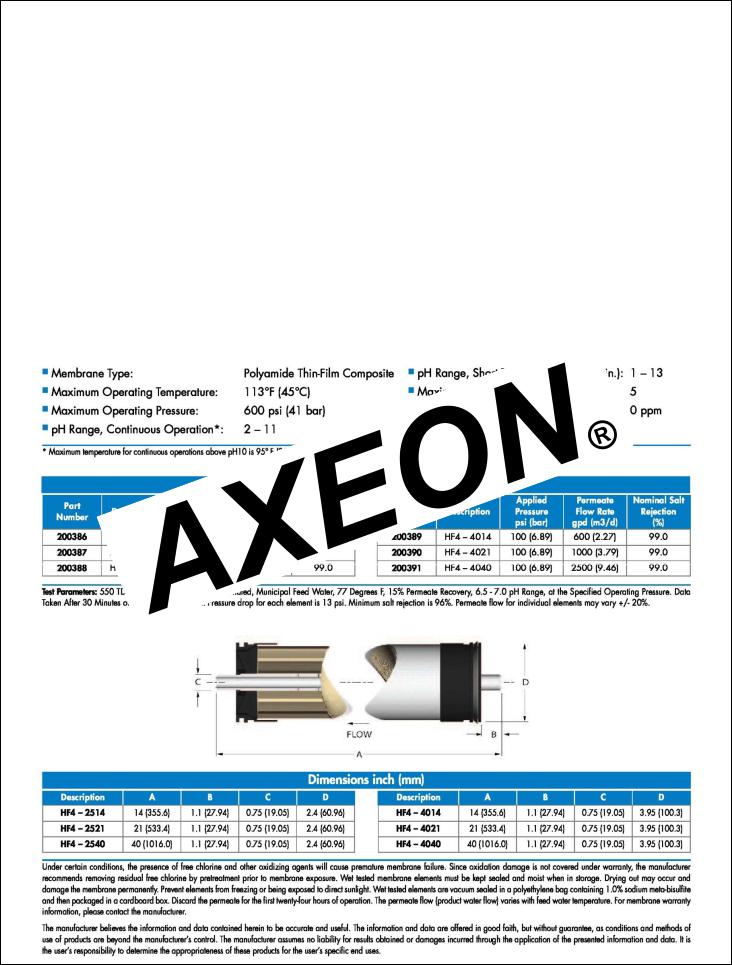
R1-Series reverse osmosis systems come pre-loaded with Thin Film Composite (TFC) HF4 High Flow Extra Low Energy membranes, unless otherwise specified. General membrane element performance characteristics are listed on the following pages:
HF4-STANDARD
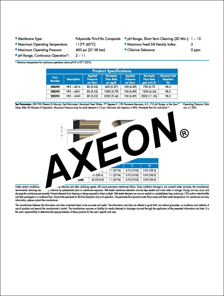
HF5-OPTIONAL
9
MKTF - 211 |
07/26/12 |

NF3-OPTIONAL
10
MKTF - 211 |
07/26/12 |
NF4-OPTIONAL
11
MKTF - 211 |
07/26/12 |
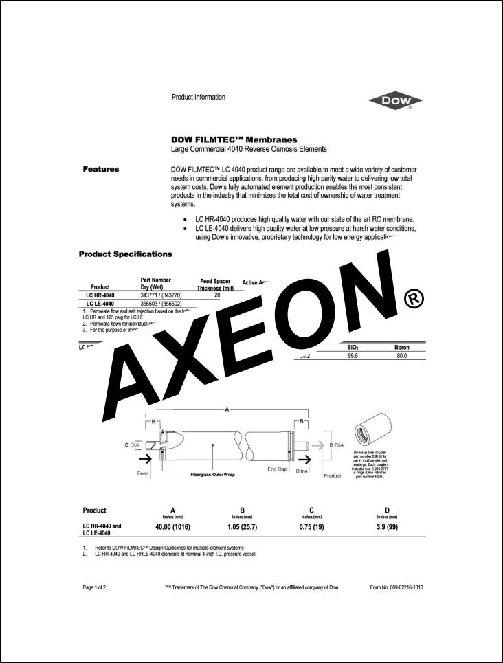
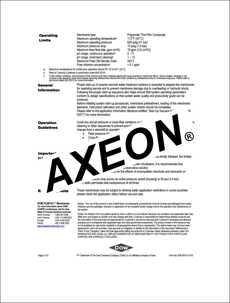
LC LE-4040-OPTIONAL
12
MKTF - 211 |
07/26/12 |

13
MKTF - 211 |
07/26/12 |

LC HR-4040-OPTIONAL
14
MKTF - 211 |
07/26/12 |
15
MKTF - 211 |
07/26/12 |
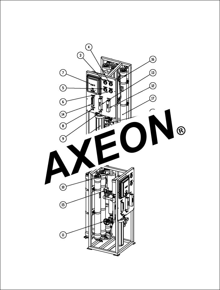
R1-1140, R1-2140, R1-3140, R1-4140, R1-5140, R1-6140
SYSTEM IDENTIFICATION
FIGURE 1A
16
MKTF - 211 |
07/26/12 |

NUMBER IDENTIFICATION
1.SOLENOID VALVE – TURNS ON/OFF FEED WATER
2.5 MICRON SEDIMENT – REMOVES PARTICULATES
3.PRESSURE GAUGE – MEASURES FEED PRESSURE
4.PRESSURE GAUGE – MEASURES PRESSURE AFTER FILTERS
5.PRESSURE GAUGE – MEASURES PUMP PRESSURE
6.PRESSURE GAUGE – MEASURES CONCENTRATE PRESSURE
7.COMPUTER CONTROL – CONTROLS RO SYSTEM FUNCTIONS
9. |
TO |
10.
11.
12.
13.FLOW METER – MEASURES FLOW OF CONCENTRATE (WASTE) WATER
14.FLOW METER – MEASURES FLOW OF CONCENTRATE RECYCLE WATER
15.PRESSURE SWITCH – TURNS OFF RO PUMP WHEN FEED PRESSURE FALLS BELOW 15PSI
16.PERMEATE CHECK VALVE – PROTECTS MEMBRANE ELEMENTS FROM BACKPRESSURE
17.PRESSURE VESSELS – HOUSES MEMBRANE ELEMENTS
18.PERMEATE SAMPLE VALVE- MEASURES THE QUALITY OF EACH MEMBRANE
17
MKTF - 211 |
07/26/12 |

FIGURE
18
MKTF - 211 |
07/26/12 |
 Loading...