

Page 1
www.burkert.com
We reserve the right to make
technical changes without notice.
Technische Änderungen
vorbehalten.
Sous réserve de modifications
techniques.
© 2009 - 2011 Bürkert Werke GmbH
Operating Instructions
1106/07_EU-ml_00893124
/ Original DE
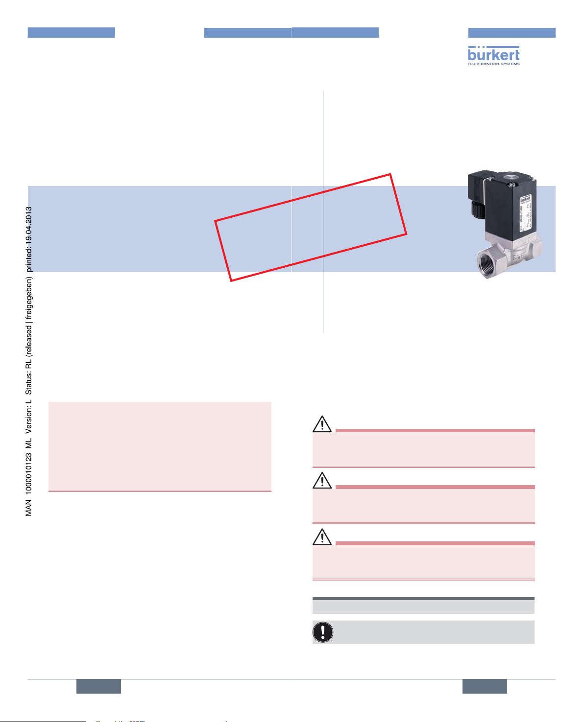
Type 0290
2/2-way solenoid valve
2/2-Wege Magnetventil
Electrovanne 2/2 voies
Operating Instructions
Bedienungsanleitung
Manuel d‘utilisation
2
1. OPERATING INSTRUCTIONS
The operating instructions contain important
information.
• Read the instructions carefully and follow the safety
instructions in particular.
• Keep the instructions in a location where they are available to every user.
• The liability and warranty for Type 0290 are void if the
operating instructions are not followed.
english
3
2. SYMBOLS
The following symbols are used in these instructions.
DANGER!
Warns of an immediate danger!
• Failure to observe the warning may result in a fatal or
serious injury.
WARNING!
Warns of a potentially dangerous situation!
• Failure to observe the warning may result in a serious or
fatal injury.
CAUTION!
Warns of a possible danger!
• Failure to observe this warning may result in a medium
or minor injury.
NOTE!
Warns of damage to property!
Important tips and recommendations.
→ designates a procedure which you must carry out.
english
Voltage 12V or 24V
UL / UR valid with
class 2 power supply only
Page 2
4
3. INTENDED USE
Incorrect use of the solenoid valve Type 0290 can
be dangerous to people, nearby equipment and the
environment.
• The device is designed for dosing, blocking, filling and
aerating media.
• Use according to the permitted data, operating conditions
and conditions of use specified in the contract documents
and operating instructions. These are described in the
chapter entitled 6.Technical Data.
• The device may be used only in conjunction with thirdparty devices and components recommended and
authorised by Bürkert.
• Correct transportation, correct storage and installation
and careful use and maintenance are essential for reliable
and problem-free operation.
• Use the device only as intended.
3.1. Possible errors in use
• Do not physically stress the device (e.g. by placing objects
on it, using it as a screwing aid, standing on it or using it
as a lever arm).
• Do not make any external modifications to the device
housings. Do not paint the housing parts or screws.
english
5
3.2. Approvals
The approval rating on the Bürkert labels concerns to Bürkert
products.
Devices that carry the e1 marking have been approved by
the Federal Office for Motorized Transport under the type
approval number
e1*72/245*2006/96*5791*00
and will be brought into circulation with the indicated approval
designation.
You can obtain an excerpt from the type approval from the
address below
Bürkert Werke GmbH
Zulassungsbeauftragter
Christian-Bürkert-Str. 13-17
D-74653 Ingelfingen
english
6
4. BASIC SAFETY
INSTRUCTIONS
These safety instructions do not make allowance for any:
• Contingencies and events which may arise during the installation, operation and maintenance of the devices.
• Local safety regulations – the operator is responsible for
observing these regulations, also with reference to the
installation personnel.
Danger – high pressure!
• Before loosening the lines and valves, turn off the pressure and vent the lines.
Risk of electric shock!
• Before reaching into the 0290, switch off the power supply and secure to prevent reactivation!
• Observe applicable accident prevention and safety
regulations for electrical equipment!
Risk of burns/Risk of fire if used continuously through
hot device surface!
• Keep the device away from highly flammable substances
and media and do not touch with bare hands.
english
7
General hazardous situations.
To prevent injury, ensure that:
• The system cannot be activated unintentionally.
• Installation and repair work may be carried out by authorized technicians only and with the appropriate tools.
• After an interruption in the power supply or pneumatic
supply, ensure that the process is restarted in a defined
or controlled manner.
• The device may be operated only when in perfect condition and in consideration of the operating instructions.
• The general rules of technology apply to application planning and operation of the device.
CAUTION!
Risk of injury due to malfunction of valves with alternating current (AC).
Sticking core causes coil to overheat, resulting in a
malfunction.
• Monitor process to ensure function is in perfect working
order!
english
Type 0290
Page 3
8
4.1. Design with explosion
protection
DANGER!
Danger of explosion!
Improper use in hazardous explosive areas will result in
danger of explosion.
english
9
5. GENERAL INFORMATION
5.1. Contact address
Germany
Bürkert Fluid Control Systems
Sales Center
Chr.-Bürkert-Str. 13-17
D-74653 Ingelfingen
Tel. + 49 (0) 7940 - 10 91 111
Fax + 49 (0) 7940 - 10 91 448
E-mail: info@de.buerkert.com
International
Contact addresses can be found on the final pages of the
printed operating instructions.
And also on the internet at:
www.burkert.com
5.2. Information on the Internet
The operating instructions and data sheets for Type 0290
can be found on the Internet at:
www.burkert.com
Documentation
Type 0290
english
10
6. TECHNICAL DATA
6.1. Operating Conditions
Ambient temperature: max. +55 °C
Permitted medium temperature depending on seal
material and coil model:
Seal material Model with high
power or rectifier
AC/DC*
Model without
electronics
50 Hz, 60 Hz*
NBR -10 ... +80 °C -10 ... +80 °C
FKM 0 ... +90 °C 0 ... +120 °C
EPDM -30 ... +90 °C -30 ... +120 °C
* Rating plate information
Permitted media depending on seal material:
Seal material Permitted media
NBR Neutral media, compressed air, water,
hydraulic oil
FKM Per-solutions, hot oils
EPDM Oil and grease-free media e.g. hot water
Protection class: IP65 in accordance with device socket
english
11
6.2. Conformity
In accordance with the EC Declaration of conformity, Type
0290 is compliant with the EC Directives.
6.3. Standards
The conformity with EC guidelines is guaranteed in accordance with standards:
EN 60204-1, EN61010-1, EN60730-1, EN 60730-2-8
6.4. Mechanical Data
Dimensions: see data sheet
Body material: Brass, Stainless steel (1.4581),
Gray cast iron
Sealing material: NBR, FKM, EPDM
6.5. Fluidic Data
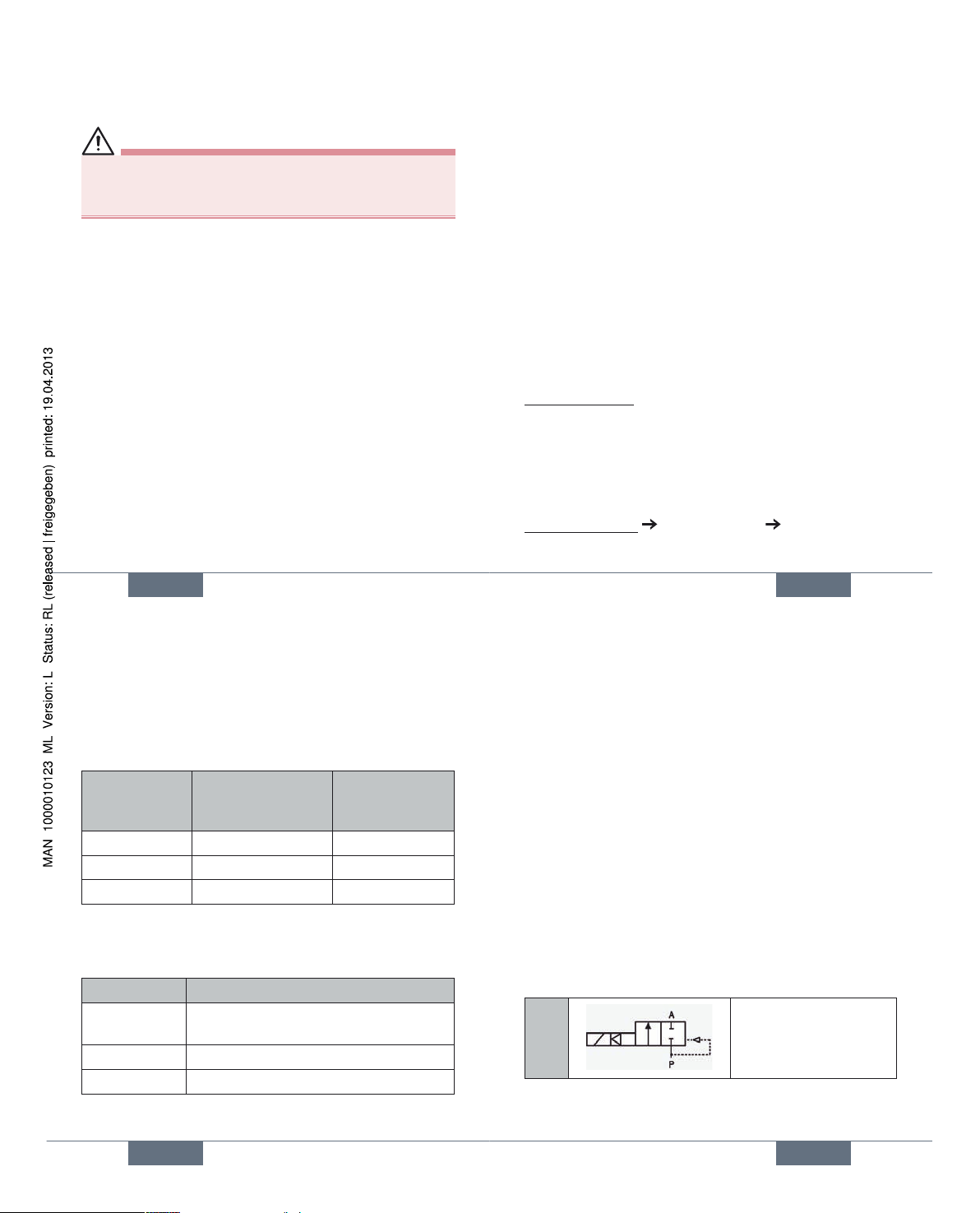
Circuit functions
A
(NC)
2/2-way valve,
direct-acting, normal
output A unloaded
Pressure range: according to the design (see rating
plate)
english
Type 0290
Page 4
12
6.6. Rating plate (Example)
0290 A 20,0 FKM VA
Made in Germany
00153212
W1Y LU
230 V 50 Hz 16 W
G 3/4 P
N 0 - 16 bar
Typ e
Operating
prinziple
Orifice
Seal material
Housing material
Identification
number
Manufacturer code
Voltage, Frequency, Power
consumption
Port connection, Nominal
pressure
english
13
6.7. Electrical data
Connections: DIN EN 175301-803 Form A for
device socket Type 2508
Power supply: 24 V DC,
max. residual ripple 10 %,
24 V / 50 Hz, 110 V / 50 Hz,
230 V / 50 Hz
Voltage tolerance: ± 10 %
Nominal operating mode: long-term operation, ED 100%
Note the information specified on the label for
voltage, type of current, and pressure.
english
14
7. INSTALLATION
WARNING!
Risk of injury from improper installation!
• Installation may be carried out by authorized technicians
only and with the appropriate tools!
Risk of injury from unintentional activation of the
system and an uncontrolled restart!
• Secure system from unintentional activation.
• Following installation, ensure a controlled restart.
7.1. Fluid installation
DANGER!
Risk of injury from high pressure in the equipment!
• Before loosening the lines and valves, turn off the pressure and vent the lines.
Installation position:
Installation can be in any position.
Preferably: Actuator upright.
Procedure:
→ Before installation, clean any possible dirt off the
pipelines.
english
15
→ If required, install a dirt trap to prevent malfunctions.
Mesh size: 0.2 ... 0.4 mm
WARNING!
Risk of short-circuit or escape of media through
leaking screw joints.
• Ensure seals are seated correctly!
• Carefully screw together coil and device socket or valve
and pipelines!
Observe direction of flow of the valve:
1 → 2 (P → A).
→ Seal the pipe connection with PTFE tape.
The PTFE tape must not get into the device.
NOTE!
Caution risk of breakage!
• Do not use the coil as a lifting arm.
→ Hold the device with a suitable tool (Open-end wrench)
on the housing and screw into the pipeline
english
Type 0290
Page 5
16
7.2. Electrical installation
DANGER!
Risk of injury due to electrical shock!
• Before reaching into the system, switch off the power
supply and secure to prevent reactivation!
• Observe applicable accident prevention and safety
regulations for electrical equipment!
WARNING!
Danger of electrical shock if the protective conductor
contact between the coil and housing is missing!
• Always connect protective conductor.
• Check electrical continuity between coil and housing.
Risk of short-circuit or escape of media through
leaking screw joints.
• Ensure seals are seated correctly!
• Carefully screw together coil and device socket or valve
and pipelines!
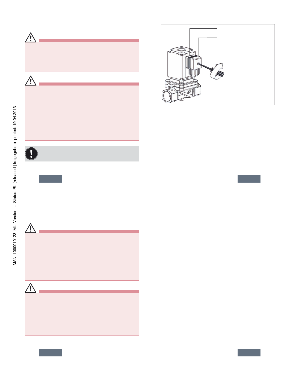
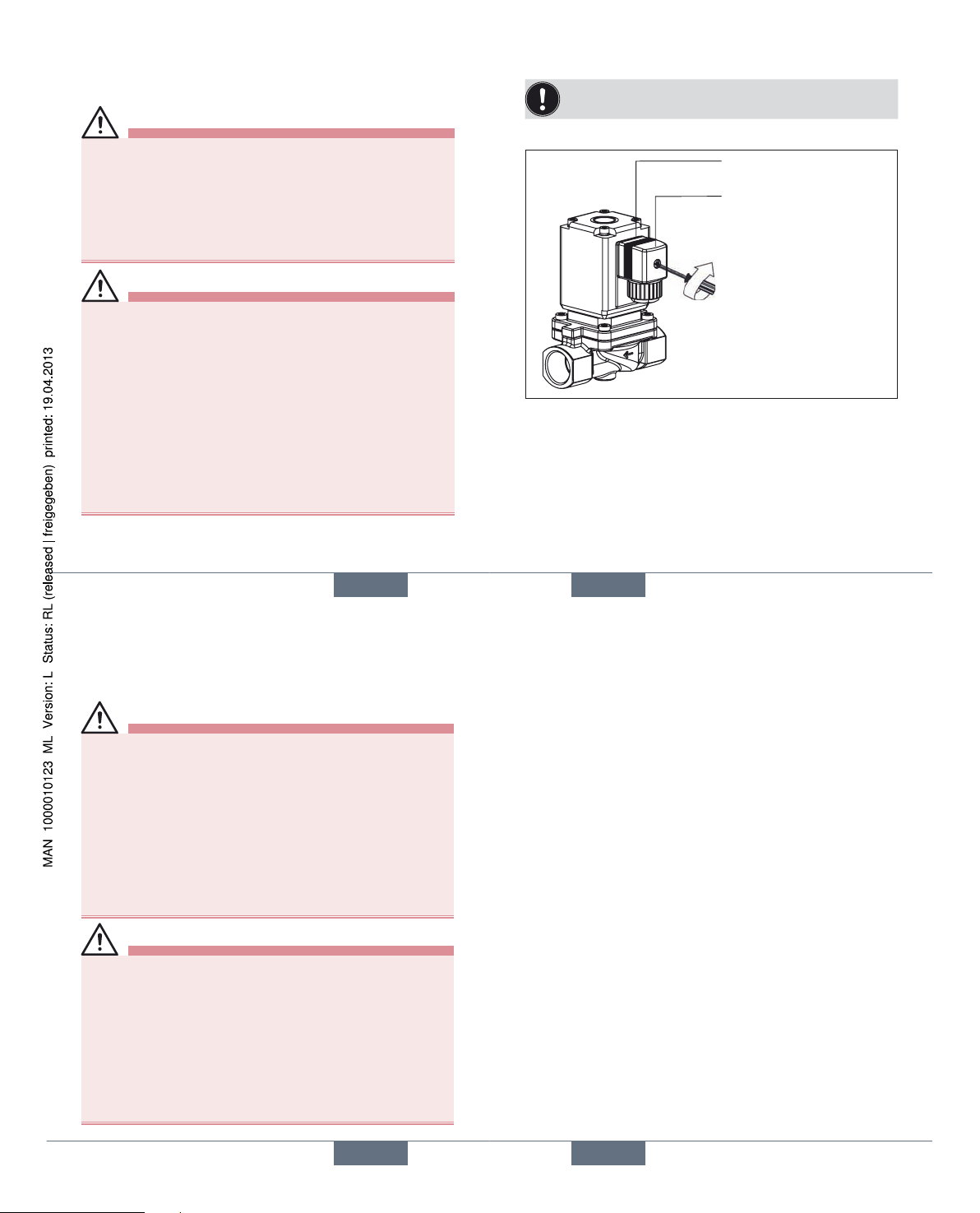
Note the voltage and current type as specified on
the label.
english
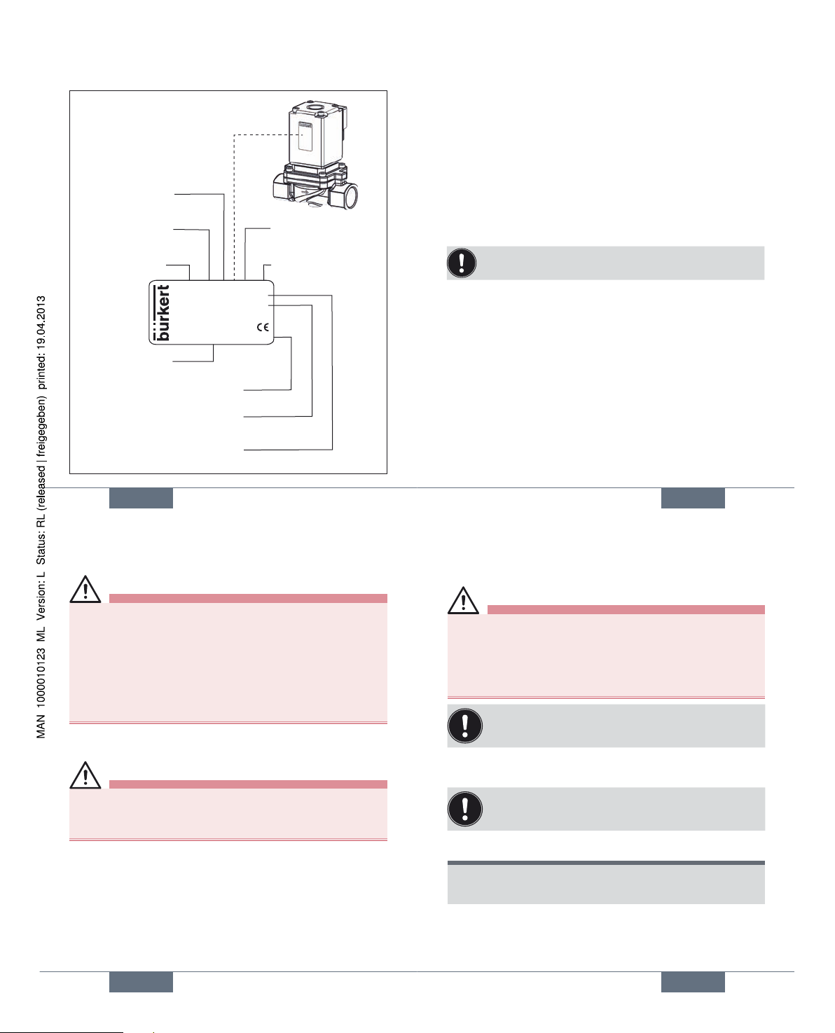
17
max. 1 Nm
Seal
Authorised cable plug
Type 2508
Fig. 1: Electrical installation
english
18
8. MAINTENANCE,
TROUBLESHOOTING
8.1. Safety instructions
DANGER!
Risk of injury from high pressure in the equipment!
• Before loosening the lines and valves, turn off the pressure and vent the lines.
Risk of injury due to electrical shock!
• Before reaching into the system, switch off the power
supply and secure to prevent reactivation!
• Observe applicable accident prevention and safety
regulations for electrical equipment!
WARNING!
Risk of injury from improper maintenance!
• Maintenance may be carried out by authorized technicians
only and with the appropriate tools!
Risk of injury from unintentional activation of the
system and an uncontrolled restart!
• Secure system from unintentional activation.
• Following maintenance, ensure a controlled restart.
english
19
8.2. Malfunctions
Troubles
If malfunctions occur, check whether:
• the device has been installed according to the
instructions,
• the connections are correct,
• the device is not damaged,
• all screws have been tightened,
• the voltage and pressure have been switched on,
• the pipelines are clean.
If the magnet does not pick up, ensure that:
• there is no short-circuit or coil interruption,
• the core / core area is not dirty.
If the valve still does not switch, please contact your Bürkert
Service.
english
Type 0290
Page 6
20
9. SPARE PARTS
CAUTION!
Risk of injury and/or damage by the use of incorrect
parts!
Incorrect accessories and unsuitable spare parts may cause
injuries and damage the device and the surrounding area.
• Use only original accessories and original spare parts
from Bürkert.
9.1. Ordering spare parts
Replacement part sets
Order spare-part sets by quoting:
• Order the coil set by quoting the identification number of
the device.
• For wearing part sets see Chapter 9.2.2.Wearing-parts set.
• For housing spare parts see Chapter 9.2.1.Spare parts:
Housing.
english
21
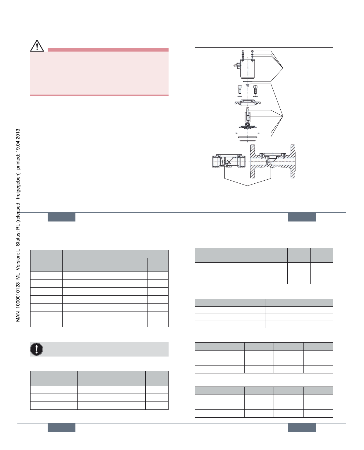
9.2. Overview of replacement spare
sets
Coil set
Wearing-parts set
Housing
Fig. 2: Overview of replacement spare sets
english
22
9.2.1. Spare parts: Housing
Orifice/
Port
connection
Material / Type of connection
MS
G
MS
NPT
VA
G
VA
NPT
GG
Flange
DN12, 1/2“
605796 612061 607982 61206 0 -
DN20, 3/4“
621546 621547 623912 623913 -
DN25, 1“
621548 621549 623916 623917 615902
DN32, 1 1/4“
613365 61419 5 - - 614214
DN40, 1 1/2“
613364 614223 - - 6142 36
DN50, 2“
614245 61424 6 - - 614259
DN65, 2 1/2“
6142 68 614269 - - -
9.2.2. Wearing-parts set
The number of parts in the wearing part set may vary
depending on the nominal size.
Housing material: MS, GG; Frequency 50 Hz, 60 Hz*
Seal material DN12 DN20 DN25 DN32
DN40
NBR 624347 624350 624353 015187
FKM 624348 624351 624354 015188
EPDM 624349 624352 624355 015189
* DN12, DN20, DN25
english
23
Housing material: MS, GG; Frequency UC
Seal material DN12 DN20 DN25 DN32
DN40
NBR 015160 015169 015178 015190
FKM 015161 015170 015179 015191
EPDM 015162 015171 015180 015192
Housing material: MS, GG; Frequency DC, UC
Seal material DN50/65
NBR 015193
FKM 015194
EPDM 015195
Housing material: VA; Frequency 50 Hz, 60 Hz
Seal material DN12 DN20 DN25
NBR
015163 015172 015181
FKM
015164 015173 015182
EPDM
015165 015174 015183
Housing material: VA; Frequency UC
Seal material DN12 DN20 DN25
NBR
015166 015175 015184
FKM
015167 015176 015185
EPDM
015168 015177 015186
english
Type 0290
Page 7
24
10. PACKAGING, TRANSPORT,
STORAGE, DISPOSAL
NOTE!
Transport damages!
Inadequately protected equipment may be damaged
during transport.
• During transportation protect the device against wet
and dirt in shock-resistant packaging.
• Avoid exceeding or dropping below the allowable
storage temperature.
Incorrect storage may damage the device.
• Store the device in a dry and dust-free location!
• Storage temperature. -40 ... +55 °C.
Damage to the environment caused by device components contaminated with media.
• Dispose of the device and packaging in an environmentally friendly manner.
• Observe applicable regulations on disposal and the
environment.
• Observe national waste disposal regulations.
english
Type 0290
Page 8

www.burkert.com
We reserve the right to make
technical changes without notice.
Technische Änderungen
vorbehalten.
Sous réserve de modifications
techniques.
© 2009 - 2011 Bürkert Werke GmbH
Operating Instructions
1106/07_EU-ml_00893124
/ Original DE
Typ 0290
2/2-Wege Magnetventil
Bedienungsanleitung
Deutsch
26
1. DIE BEDIENUNGSANLEITUNG
Die Bedienungsanleitung enthält wichtige
Informationen.
• Die Anleitung sorgfältig lesen und besonders die Hinweise zur Sicherheit beachten.
• Die Anleitung so aufbewahren, dass sie jedem Benutzer zur Verfügung steht.
• Die Haftung und Gewährleistung für Typ 0290 entfällt,
wenn die Anweisungen der Bedienungsanleitung nicht
beachtet werden.
deutsch
27
2. DARSTELLUNGSMITTEL
In dieser Anleitung werden folgende Darstellungsmittel
verwendet.
GEFAHR!
Warnt vor einer unmittelbaren Gefahr!
• Bei Nichtbeachtung sind Tod oder schwere Verletzungen die Folge.
WARNUNG!
Warnt vor einer möglicherweise gefährlichen Situation!
• Bei Nichtbeachtung können schwere Verletzungen oder
Tod die Folge sein.
VORSICHT!
Warnt vor einer möglichen Gefährdung!
• Nichtbeachtung kann mittelschwere oder leichte Verletzungen zur Folge haben.
HINWEIS!
Warnt vor Sachschäden!
Wichtige Tipps und Empfehlungen.
→ markiert einen Arbeitsschritt den Sie ausführen müssen.
deutsch
Voltage 12V or 24V
UL / UR valid with
class 2 power supply only
Page 9

28
3. BESTIMMUNGSGEMÄSSE
VERWENDUNG
Bei nicht bestimmungsgemäßem Einsatz des Magnetventils Typ 0290 können Gefahren für Personen,
Anlagen in der Umgebung und die Umwelt entstehen.
• Das Gerät ist zum Dosieren, Sperren, Füllen und Belüften
von Medien konzipiert.
• Für den Einsatz die in den Vertragsdokumenten und der
Bedienungsanleitung spezifizierten zulässigen Daten,
Betriebs- und Einsatzbedingungen beachten. Diese sind
im Kapitel 6.Technische Daten beschrieben.
• Das Gerät nur in Verbindung mit von Bürkert empfohlenen bzw. zugelassenen Fremdgeräten und -komponenten
einsetzen.
• Voraussetzungen für den sicheren und einwandfreien
Betrieb sind sachgemäßer Transport, sachgemäße
Lagerung und Installation sowie sorgfältige Bedienung
und Instandhaltung.
• Setzen Sie das Gerät nur bestimmungsgemäß ein.
3.1. Vorhersehbarer Fehlgebrauch
• Belasten Sie das Gerät nicht mechanisch (z. B. durch
Ablage von Gegenständen, Einschraubhilfe, Trittstufe oder
als Hebelarm).
deutsch
29
• Nehmen Sie keine äußerlichen Veränderungen an den
Gerätegehäusen vor. Gehäuseteile und Schrauben nicht
lackieren.
3.2. Zulassungen
Die auf den Bürkert Typenschildern aufgebrachte Zulassungskennzeichnung bezieht sich auf die Bürkert Produkte. Geräte die das Typengenehmigungszeichen tragen
müssen, wurden beim Kraftfahrtbundesamt unter der
Typengenehmigungsnummer
e1*72/245*2006/96*5791*00
genehmigt und werden mit dem gezeigten Typengenehmigungszeichen in den Verkehr gebracht.
Einen Auszug der Typgenehmigung erhalten Sie unter der
unten stehenden Adresse.
Bürkert Werke GmbH
Zulassungsbeauftragter
Christian-Bürkert-Str. 13-17
D-74653 Ingelfingen
deutsch
30
4. GRUNDLEGENDE
SICHERHEITSHINWEISE
Diese Sicherheitshinweise berücksichtigen keine:
• Zufälligkeiten und Ereignisse, die bei Montage, Betrieb und
Wartung der Geräte auftreten können.
• Ortsbezogenen Sicherheitsbestimmungen, für deren
Einhaltung, auch in Bezug auf das Montagepersonal, der
Betreiber verantwortlich ist.
Gefahr durch hohen Druck!
• Vor dem Lösen von Leitungen oder Ventilen den Druck
abschalten und Leitungen entlüften.
Gefahr durch elektrische Spannung!
• Vor Eingriffen in das Gerät oder die Anlage, Spannung
abschalten und vor Wiedereinschalten sichern!
• Die geltenden Unfallverhütungs- und Sicherheitsbestimmungen für elektrische Geräte beachten!
Verbrennungsgefahr/Brandgefahr bei Dauerbetrieb
durch heiße Geräteoberfläche!
• Das Gerät von leicht brennbaren Stoffen und Medien
fernhalten und nicht mit bloßen Händen berühren.
deutsch
31
Allgemeine Gefahrensituationen.
Zum Schutz vor Verletzungen ist zu beachten:
• Dass die Anlage nicht unbeabsichtigt betätigt werden
kann.
• Installations- und Instandhaltungsarbeiten dürfen nur
von autorisiertem Fachpersonal mit geeignetem Werkzeug ausgeführt werden.
• Nach einer Unterbrechung der elektrischen oder pneumatischen Versorgung ist ein definierter oder kontrollierter Wiederanlauf des Prozesses zu gewährleisten.
• Das Gerät darf nur in einwandfreiem Zustand und
unter Beachtung der Bedienungsanleitung betrieben
werden.
• Für die Einsatzplanung und den Betrieb des Gerätes
müssen die allgemeinen Regeln der Technik eingehalten werden.
VORSICHT!
Verletzungsgefahr durch Funktionsausfall bei Ventilen
mit Wechselspannung (AC).
Festsitzender Kern bewirkt Spulenüberhitzung, die zu
Funktionsausfall führt.
• Arbeitsprozess auf einwandfreie Funktion überwachen!
deutsch
Typ 0290
Page 10

32
4.1. Ausführungen mit
Explosionsschutz
GEFAHR!
Explosionsgefahr!
Bei unsachgemäßem Einsatz im explosionsgefährdeten
Bereich besteht Explosionsgefahr.
deutsch
33
5. ALLGEMEINE HINWEISE
5.1. Kontaktadressen
Deutschland
Bürkert Fluid Control Systems
Sales Center
Christian-Bürkert-Str. 13-17
D-74653 Ingelfingen
Tel. + 49 (0) 7940 - 10 91 111
Fax + 49 (0) 7940 - 10 91 448
E-mail: info@de.buerkert.com
International
Die Kontaktadressen finden Sie auf den letzten Seiten der
gedruckten Bedienungsanleitung.
Außerdem im Internet unter:
www.burkert.com
5.2. Informationen im Internet
Bedienungsanleitungen und Datenblätter zum Typ 0290
finden Sie im Internet unter:
www.buerkert.de
deutsch
34
6. TECHNISCHE DATEN
6.1. Betriebsbedingungen
Umgebungstemperatur: max. +55 °C
Zulässige Mediumstemperatur in Abhängigkeit von Dicht-
werkstoff und Spulenausführung:
Dichtwerk-
stoff
Ausführung mit
Hochleistung oder
Gleichrichter AC/DC*
Ausführung
ohne Elektronik
50 Hz, 60 Hz*
NBR -10 ... +80 °C -10 ... +80 °C
FKM 0 ... +90 °C 0 ... +120 °C
EPDM -30 ... +90 °C -30 ... +120 °C
* Typenschildangaben
Zulässige Medien in Abhängigkeit vom Dichtwerkstoff:
Dichtwerkstoff Zulässige Medien
NBR Neutrale Medien, Druckluft, Wasser,
Hydrauliköl
FKM Per-Lösungen, heiße Öle
EPDM Öl- und fettfreie Medien z. B.
Heißwasser
Schutzart IP65 mit Gerätesteckdose
deutsch
35
6.2. Konformität
Der Typ 0290 ist konform zu den EG-Richtlinien entsprechend
der EG-Konformitätserklärung.
6.3. Normen
Durch folgende Normen wird die Konformität mit der EGRichtlinie erfüllt.
EN 60204-1, EN61010-1, EN60730-1, EN 60730-2-8
6.4. Mechanische Daten
Maße: siehe Datenblatt
Gehäusematerial: Messing, Edelstahl (1.4581),
Grauguss
Dichtungsmaterial: NBR, FKM, EPDM
6.5. Fluidische Daten
Wirkungsweise
A
(NC)
2/2-Wege-Ventil,
direktwirkend, stromlos
Ausgang A entlastet
Druckbereich: entsprechend der Ausführung
(siehe Typenschild)
deutsch
Typ 0290
Page 11

36
6.6. Typenschild (Beispiel)
0290 A 20,0 FKM VA
Made in Germany
00153212
W1Y LU
230 V 50 Hz 16 W
G 3/4 P
N 0 - 16 bar
Typ
Wirkungsweise
Nennweite
Dichtwerkstoff
Gehäusewerkstoff
Identnummer
Hersteller-Code
Spannung, Frequenz, Leistung
Leitungsanschluss, Nenndruck
deutsch
37
6.7. Elektrische Daten
Anschlüsse: DIN EN 175301-803 Form A für
Gerätesteckdose Typ 2508
Spannungsversorgung: 24 V DC,
Max. Restwelligkeit 10 %,
24 V / 50 Hz, 110 V / 50 Hz,
230 V / 50 Hz
Spannungstoleranz: ± 10 %
Nennbetriebsart: Dauerbetrieb, ED 100 %
Spannung und Stromart laut Typenschild beachten.
deutsch
38
7. INSTALLATION
WARNUNG!
Verletzungsgefahr bei unsachgemäßer Installation!
• Die Installation darf nur autorisiertes Fachpersonal mit
geeignetem Werkzeug durchführen!
Verletzungsgefahr durch ungewolltes Einschalten
der Anlage und unkontrollierten Wiederanlauf!
• Anlage vor unbeabsichtigtem Betätigen sichern.
• Nach der Installation einen kontrollierten Wiederanlauf
gewährleisten.
7.1. Fluidische Installation
GEFAHR!
Verletzungsgefahr durch hohen Druck in der Anlage!
• Vor dem Lösen von Leitungen oder Ventilen den Druck
abschalten und Leitungen entlüften.
Einbaulage:
Die Einbaulage ist beliebig.
Vorzugsweise: Antrieb oben.
Vorgehensweise:
→ Vor der Montage Rohrleitungen von eventuellen Ver-
schmutzungen säubern.
deutsch
39
→ Zum Schutz vor Störungen gegebenenfalls einen
Schmutzfänger einbauen.
Maschenweite: 0,2 ... 0,4 mm
WARNUNG!
Kurzschlussgefahr bzw. Austritt von Medium bei
undichten Verschraubungen.
• Auf einwandfreien Sitz der Dichtungen achten!
• Spule und Gerätesteckdose bzw. Ventil und Rohrleitungen sorgfältig verschrauben!
Durchflussrichtung des Ventils beachten:
1 → 2 (P → A).
→ Die Rohrverbindung mit PTFE-Band abdichten.
Das PTFE-Band darf nicht in das Gerät gelangen.
HINWEIS!
Vorsicht Bruchgefahr!
• Die Spule darf nicht als Hebelarm benutzt werden.
→ Das Gerät mit geeignetem Werkzeug (Gabelschlüssel)
am Gehäuse festhalten und in die Rohrleitung
einschrauben.
deutsch
Typ 0290
Page 12

40
7.2. Elektrische Installation
GEFAHR!
Verletzungsgefahr durch Stromschlag!
• Vor Eingriffen in das Gerät oder die Anlage, Spannung
abschalten und vor Wiedereinschalten sichern!
• Die geltenden Unfallverhütungs- und Sicherheitsbestimmungen für elektrische Geräte beachten!
WARNUNG!
Verletzungsgefahr durch Stromschlag bei fehlendem
Schutzleiterkontakt zwischen Spule und Gehäuse!
• Schutzleiter immer anschließen!
• Schutzleiterkontakt nach der Spulenmontage prüfen!
Kurzschlussgefahr bzw. Austritt von Medium bei
undichten Verschraubungen.
• Auf einwandfreien Sitz der Dichtungen achten!
• Spule und Gerätesteckdose bzw. Ventil und Rohrleitungen sorgfältig verschrauben!
Spannung und Stromart laut Typenschild beachten.
deutsch
41
max. 1 Nm
Dichtung
Zugelassene
Gerätesteckdose Typ 2508
Bild 1: Elektrische Installation
deutsch
42
8. WARTUNG,
FEHLERBEHEBUNG
8.1. Sicherheitshinweise
GEFAHR!
Verletzungsgefahr durch hohen Druck in der Anlage!
• Vor dem Lösen von Leitungen und Ventilen den Druck
abschalten und Leitungen entlüften.
Verletzungsgefahr durch Stromschlag!
• Vor Eingriffen in das Gerät oder die Anlage, Spannung
abschalten und vor Wiedereinschalten sichern!
• Die geltenden Unfallverhütungs- und Sicherheitsbestimmungen für elektrische Geräte beachten!
WARNUNG!
Verletzungsgefahr bei unsachgemäßen
Wartungsarbeiten!
• Die Wartung darf nur autorisiertes Fachpersonal mit
geeignetem Werkzeug durchführen!
Verletzungsgefahr durch ungewolltes Einschalten
der Anlage und unkontrollierten Wiederanlauf!
• Anlage vor unbeabsichtigtem Betätigen sichern.
• Nach der Wartung einen kontrollierten Wiederanlauf
gewährleisten.
deutsch
43
8.2. Wartungsarbeiten
Störungen
Bei Störungen sicherstellen, dass:
• das Gerät vorschriftsmäßig installiert ist,
• der Anschluss ordnungsgemäß ausgeführt ist,
• das Gerät nicht beschädigt ist,
• alle Schraubverbindungen fest angezogen sind,
• Spannung und Druck anliegen,
• die Rohrleitungen schmutzfrei sind.
Zieht der Magnet nicht an, sicherstellen dass:
• kein Kurzschluss oder Spulenunterbrechung vorliegt,
• der Kern / Kernraum nicht verschmutzt ist.
Falls das Ventil dennoch nicht schaltet, wenden Sie sich bitte
an Ihren Bürkert-Service.
deutsch
Typ 0290
Page 13

44
9. ERSATZTEILE
VORSICHT!
Verletzungsgefahr, Sachschäden durch falsche Teile!
Falsches Zubehör und ungeeignete Ersatzteile können
Verletzungen und Schäden am Gerät und dessen
Umgebung verursachen.
• Nur Originalzubehör sowie Originalersatzteile der
Firma Bürkert verwenden.
9.1. Ersatzteilsätze
Ersatzteilsätze
Bestellen Sie Ersatzteilsätze unter Angaben:
• Bestellen Sie den Spulensatz unter Angabe der Identnummer des Gerätes.
• Verschleißteilsätze siehe Kapitel 9.2.2.Ersatzteile
Verschleißteilsatz.
• Ersatzteile Gehäuse siehe Kapitel 9.2.1.Ersatzteile
Gehäuse.
deutsch
45
9.2. Übersicht Ersatzteilsätze
Spulensatz
Verschleißteilsatz
Gehäuse
Bild 2: Übersicht Ersatzteilsätze
deutsch
46
9.2.1. Ersatzteile Gehäuse
Nennweite
Leitungsan-
schluss
Werkstoff / Anschlussart
MS GMS
NPT
VA
G
VA
NPT
GG
Flansch
DN12, 1/2“ 605796 612061 607982 61206 0 DN20, 3/4“ 621546 621547 623912 623913 DN25, 1“ 621548 621549 623916 62 3 917 615902
DN32, 1 1/4“ 613365 61419 5 - - 614214
DN40, 1 1/2“ 613364 614223 - - 614236
DN50, 2“ 614245 614246 - - 614259
DN65, 2 1/2“ 614268 614269 - - -
9.2.2. Ersatzteile Verschleißteilsatz
Die Anzahl der Teile des Verschleißteilsatzes kann je
nach Nennweite variieren.
Gehäusewerkstoff: MS, GG; Frequenz 50 Hz, 60 Hz*
Dichtwerkstoff DN12 DN20 DN25 DN32
DN40
NBR 624347 624350 624353 015187
FKM 624348 624351 624354 015188
EPDM 624349 624352 624355 015189
* DN12, DN20, DN25
deutsch
47
Gehäusewerkstoff: MS, GG; Frequenz UC
Dichtwerkstoff DN12 DN20 DN25 DN32
DN40
NBR 015160 015169 015178 015190
FKM 015161 015170 015179 015191
EPDM 015162 015171 015180 015192
Gehäusewerkstoff: MS, GG; Frequenz DC, UC
Dichtwerkstoff DN50/65
NBR 015193
FKM 015194
EPDM 015195
Gehäusewerkstoff: VA; Frequenz 50 Hz, 60 Hz
Dichtwerkstoff DN12 DN20 DN25
NBR
015163 015172 015181
FKM
015164 015173 015182
EPDM
015165 015174 015183
Gehäusewerkstoff: VA; Frequenz UC
Dichtwerkstoff DN12 DN20 DN25
NBR
015166 015175 015184
FKM
015167 015176 015185
EPDM
015168 015177 015186
deutsch
Typ 0290
Page 14
48
10. VERPACKUNG, TRANSPORT,
LAGERUNG, ENTSORGUNG
HINWEIS!
Transportschäden!
Unzureichend geschützte Geräte können durch den
Transport beschädigt werden.
• Gerät vor Nässe und Schmutz geschützt in einer stoßfesten Verpackung transportieren.
• Eine Über- bzw. Unterschreitung der zulässigen Lagertemperatur vermeiden.
Falsche Lagerung kann Schäden am Gerät
verursachen.
• Gerät trocken und staubfrei lagern!
• Lagertemperatur. -40 … +55 °C.
Umweltschäden durch von Medien kontaminierte
Geräteteile.
• Gerät und Verpackung umweltgerecht entsorgen!
• Geltende Entsorgungsvorschriften und Umweltbestimmungen einhalten.
deutsch
Typ 0290
Page 15

www.burkert.com
We reserve the right to make
technical changes without notice.
Technische Änderungen
vorbehalten.
Sous réserve de modifications
techniques.
© 2009 - 2011 Bürkert Werke GmbH
Operating Instructions
1106/07_EU-ml_00893124
/ Original DE
Type 0290
Electrovanne 2/2 voies
Manuel d‘utilisation
Français
50
1. LE MANUEL D’UTILISATION
Le manuel d‘utilisation contiennent des informations
importantes.
• Lire attentivement le manuel et tenir particulièrement
compte des consignes de sécurité.
• Conserver le manuel d’utilisation afin qu’il soie accessible à tous les utilisateurs.
• La responsabilité et la garantie légale concernant le type
0290 sont exclues en cas de non-respect des instructions de service.
français
51
2. SYMBOLES
Les moyens de représentation suivants sont utilisés dans
les présentes instructions de service.
DANGER !
Met en garde contre un danger imminent !
• Le non-respect peut entraîner la mort ou de graves
blessures.
AVERTISSEMENT !
Met en garde contre une situation éventuellement
dangereuse !
• Le non-respect peut entraîner de graves blessures ou
la mort.
ATTENTION !
Met en garde contre un risque possible !
• Le non-respect peut entraîner des blessures légères ou
de moyenne gravité.
REMARQUE !
Met en garde contre des dommages matériels !
Conseils et recommandations importants.
→ identifie une opération que vous devez effectuer.
français
Voltage 12V or 24V
UL / UR valid with
class 2 power supply only
Page 16

52
3. UTILISATION CONFORME
L’utilisation non-conforme du type 0290 peut présenter
des dangers pour les personnes, les installations avoisinantes et l’environnement.
• L’appareil est conçu pour doser, couper, remplir et
aérer des fluides.
• L’utilisation doit se faire dans le respect des données
et des conditions d’exploitation et d’utilisation spécifiées dans les documents contractuels, les instructions
de service et sur la plaque signalétique. Vous trouverez une description au chapitre 6.Caractéristiques
techniques.
• L’appareil peut être utilise uniquement en association
avec les appareils et composants étrangers recommandés et homologués par Bürkert.
• Les conditions pour l’utilisation sûre et parfaite sont
un transport, un stockage et une installation dans les
règles ainsi qu’une parfaite utilisation et maintenance.
• Veillez à ce que l’utilisation de l’appareil soit toujours
conforme.
3.1. Mauvaise utilisation prévisible
• Ne soumettez pas l’appareil à des contraintes mécaniques
(par ex. en déposant des objets dessus ou en l’utilisant
comme auxiliaire de vissage, comme marche ou encore
comme levier).
français
53
• N’apportez pas de modifications à l’extérieur du corps de
l‘appareil. Ne laquez pas les pièces du corps et les vis.
3.2. Homologations
Le marquage d’homologation apposé sur les plaques signalétiques Bürkert se rapporte aux produits Bürkert.
Les appareil portant le marque e1 ont été homologués au
Service fédéral de la circulation automobile (Kraftfahrtbundesamt) sous le numéro
e1*72/245*2006/96*5791*00
et seront mis en circulation avec la marque d’homologation
indiquée
Vous recevrez un extrait de l’homologation à l’adresse
ci-dessous:
Bürkert Werke GmbH & Co KG
Zulassungsbeauftragter
Christian-Bürkert-Str. 13-17
D-74653 Ingelfingen
français
54
4. CONSIGNES DE SÉCURITÉ
FONDAMENTALES
Ces consignes de sécurité ne tiennent pas compte :
• Des hasards et des événements pouvant survenir lors du
montage, de l‘exploitation et de l‘entretien des appareils.
• Des prescriptions de sécurité locales que l‘exploitant est
tenu de faire respecter par le personnel chargé du montage.
Danger avec haute pression !
• Avant de desserrer les tuyauteries et les vannes, coupez la pression et purgez l’air des conduites.
Danger présenté par la tension électrique !
• Avant d’intervenir dans l’appareil ou l’installation, coupez la tension et empêchez toute remise sous tension
par inadvertance !
• Veuillez respecter les réglementations en vigueur pour
les appareils électriques en matière de prévention des
accidents ainsi qu’en matière de sécurité !
Risque de brûlures / d’incendie lors d’une durée de
fonctionnement prolongée dû à la surface brûlante
de l’appareil !
• Tenez les substances et les fluides facilement inflammables à l’écart de l’appareil et ne touchez pas ce
dernier à mains nues.
français
55
Situations dangereuses d’ordre général.
Pour prévenir les blessures, respectez ce qui suit :
• L’installation ne peut pas être actionnée par
inadvertance.
• Les travaux d’installation et de maintenance doivent
être effectués uniquement par des techniciens qualifiés et habilités disposant de l’outillage approprié.
• Après une interruption de l’alimentation électrique ou
du fluide, un redémarrage défini ou contrôlé du process doit être garanti.
• L’appareil doit être utilisé uniquement en parfait état et
en respectant les instructions de service.
• Les règles générales de la technique sont à appliquer
pour l’opérationnel et l’utilisation de l’appareil.
ATTENTION !
Risque de blessure dû à une panne pour les vannes
avec tension alternative (AC).
Un noyau bloqué provoque la surchauffe de la bobine et
donc une panne.
• Surveiller le bon fonctionnement du processus de
travail !
français
Type 0290
Page 17

56
4.1. Exécutions avec protection
contre les explosions
DANGER !
Risque d’explosion !
Il y a risque d’explosion en cas d’utilisation non conforme
dans des zones présentant de tels risques.
français
57
5. INDICATIONS GÉNÉRALES
5.1. Adresses
Allemagne
Bürkert Fluid Control Systems
Sales Center
Christian-Bürkert-Str. 13-17
D-74653 Ingelfingen
Tel. + 49 (0) 7940 - 10 91 111
Fax + 49 (0) 7940 - 10 91 448
E-mail: info@de.buerkert.com
International
Les adresses se trouvent aux dernières pages des instructions de service imprimées.
Egalement sur internet sous:
www.burkert.com
5.2. Informations sur Internet
Vous trouverez sur Internet les instructions de service et fiches
techniques relatives au type 0290 :
www.buerkert.fr
français
58
6. CARACTÉRISTIQUES
TECHNIQUES
6.1. Conditions d‘exploitation
Température ambiante : max. +55 °C
Valeur admissible de la temp. du fluide en fonction du
matériau d’étanchéité et de l’exécution de la bobine:
Matériau
d’étanchéité
Exécution avec
haute puissance ou
redresseur AC/DC*
Exécution sans
électronique
50 Hz, 60 Hz*
NBR -10 ... +80 °C -10 ... +80 °C
FKM 0 ... +90 °C 0 ... +120 °C
EPDM -30 ... +90 °C -30 ... +120 °C
* Indications de la plaque signalétique
Fluides utilisables en fonction du matériau du joint :
Matériau du joint Fluides admissibles
NBR Fluides neutres, air comprimé,
eau, huile hydraulique
FKM Solution perchloréthylène, huiles
chaudes
EPDM Fluides sans huile ni graisse, ex.
eau chaude
français
59
Type de protection : IP65 avec une connecteur montée
de manière conforme
6.2. Conformité
Le type 0290 est conforme aux directives CE sur la base de
la déclaration de conformité CE.
6.3. Normes
La conformité avec les directives CE est satisfaite par les
normes suivantes :
EN 60204-1, EN61010-1, EN60730-1, EN 60730-2-8
6.4. Caractéristiques mécaniques
Dimension : voir Fiche technique
Matériau du corps : Laiton, acier inoxydable (1.4581),
fonte brute
Matériau du joint : NBR, FKM, EPDM
6.5. Caractéristiques fluidique
Fonction Vanne 2/2:
A
(NC)
Electrovanne 2/2, normalement fermée par action
du ressort
Plage de pression : correspondant à l’exécution
français
Type 0290
Page 18

60
6.6. Plaque signalétique (Exemple)
0290 A 20,0 FKM VA
Made in Germany
00153212
W1Y LU
230 V 50 Hz 16 W
G 3/4 P
N 0 - 16 bar
Typ e
Fonction
Diamètre nominal
Matériau du joint
Matériau du corps
Numéro
d’identification
Code-fabricant
Tension, fréquence, puissance
Raccordement, Pression
nominale
français
61
6.7. Caractéristiques électriques
Raccords : DIN EN 175301-803, forme
A pour prise d’appareil type
2508
Alimentation : 24 V DC, max. Ondulation
résiduelle 10 %,
24 V / 50 Hz, 110 V / 50 Hz,
230 V / 50 Hz
Tolérance de tension : ± 10 %
Mode opératoire nominal : 100 % fonctionnement
continu
Respectez la tension et le type de courant selon la
plaque signalétique.
français
62
7. INSTALLATION
AVERTISSEMENT !
Risque de blessures pour montage non conforme !
• Le montage doit être effectué uniquement par un personnel qualifié et habilité disposant de l’outillage approprié !
Risque de blessures dû à la mise en marche involontaire de l’installation et le redémarrage non contrôlé !
• Empêchez tout actionnement involontaire de l’installation.
• Garantissez un redémarrage contrôlé après le montage.
7.1. Installation fluidique
DANGER !
Danger avec haute pression !
• Avant de desserrer les tuyauteries et les vannes, coupez la pression et purgez l’air des conduites.
Position de montage :
Position de montage indifférente.
De préférence: système magnétique vers le haut.
Procédure:
→ Préalablement au montage, vérifier si les tuyaux ne pré-
sentent pas de salissures et les nettoyer le cas échéant.
français
63
→ Pour éviter tout incident, installez un filtre à poussière
en amont de l‘électrovanne.
Ouverture de maille: 0,2 ... 0,4 mm
AVERTISSEMENT !
Risque de court-circuit ou de sortie de fluide lorsque
les raccords vissés ne sont pas étanches.
• Veiller au parfait positionnement des joints !
• Visser avec soin la bobine et la prise d’appareil, respectivement la vanne et les tuyauteries !
Respecter le sens du débit de la vanne :
1 → 2 (P → A).
→ Etancher le raccord de tuyauterie avec une bande
PTFE.
La bande PTFE ne doit pas entrer dans l’appareil.
REMARQUE !
Attention risque de rupture !
• La bobine ne doit pas être utilisée comme levier.
→ Maintenez l‘appareil sur le corps à l‘aide d‘un outil
approprié (clé à fourche) et vissez-le dans la tuyauterie.
français
Type 0290
Page 19
64
7.2. Installation électriques
DANGER!
Risque de choc électrique !
• Avant d’intervenir dans l’appareil ou l’installation, coupez la tension et empêchez toute remise sous tension
par inadvertance !
• Veuillez respecter les réglementations en vigueur pour
les appareils électriques en matière de prévention des
accidents ainsi qu’en matière de sécurité !
AVERTISSEMENT !
Il y a risque de choc électrique en l’absence d’un
contact du conducteur de protection entre la bobine
et le corps !
• Raccordez toujours le conducteur de protection !
• Contrôler le passage du courant entre la bobine et le
corps !
Risque de court-circuit ou de sortie de fluide lorsque
les raccords vissés ne sont pas étanches.
• Veiller au parfait positionnement des joints !
• Visser avec soin la bobine et la prise d’appareil, respectivement la vanne et les tuyauteries !
français
65
Respectez la tension et le type de courant selon la
plaque signalétique.
max. 1 Nm
Joint
Connecteur autorisé
Type 2508
Fig. 1 : Installation électriques
français
66
8. MAINTENANCE, DÉPANNAGE
8.1. Consignes de sécurité
DANGER !
Risque de blessures dû à la présence de haute
pression dans l'installation !
• Avant de desserrer les conduites et les vannes, coupez la pression et purgez l'air des conduites.
Risque de choc électrique !
• Avant d'intervenir dans l'appareil ou l'installation, coupez la tension et empêchez toute remise sous tension
par inadvertance !
• Veuillez respecter les réglementations en vigueur pour
les appareils électriques en matière de prévention des
accidents ainsi qu'en matière de sécurité !
AVERTISSEMENT !
Risque de blessures dû à des travaux de maintenance non conformes !
• La maintenance doit être effectué uniquement par un
personnel qualifié et habilité disposant de l'outillage
approprié !
Risque de blessures dû à la mise en marche involontaire de l'installation et le redémarrage non contrôlé !
• Empêchez tout actionnement involontaire de l'installation.
• Garantissez un redémarrage contrôlé après la
maintenance.
français
67
8.2. Maintenance
Pannes
En présence de pannes, vérifiez :
• si l‘appareil est installé dans les règles,
• si le raccord électrique et fluide est correct,
• si l‘appareil n‘est pas endommagé,
• si toutes les vis sont bien serrées,
• si la tension et la pression sont disponibles,
• si les tuyauteries sont propres.
Si l’aimant n’attire pas, s’assurer :
• qu’il n’y a pas de court-circuit ou de coupure de bobine,
• que le noyau / l’espace du noyau n’est pas encrassé.
Si malgré tout la vanne ne commute pas, veuillez vous
adresser à votre service Bürkert.
français
Type 0290
Page 20

68
9. PIÈCES DE RECHANGE
ATTENTION !
Risque de blessures, de dommages matériels dus à
de mauvaises pièces !
De mauvais accessoires ou des pièces de rechange
inadaptées peuvent provoquer des blessures et endommager l'appareil ou son environnement.
• Utiliser uniquement des accessoires et des pièces de
rechange d'origine de la société Bürkert.
9.1. Commander des pièces de
rechange
Jeux de pièces de rechange
Commandez vos jeux de pièces de rechange en indiquant :
• Commandez votre jeu de bobines en indiquant le numéro
d’identification de l’appareil.
• Jeux de pièces d’usure, voir chapitre 9.2.2.Jeux de
pièces d‘usure.
• Pièces de rechange corps, voir chapitre 9.2.1.Corps.
français
69
9.2. Aperçu jeux de pièces de
rechange
Jeux de bobine
Jeux de pièces
d‘usure
Corps
Fig. 2 : Aperçut jeux de pièces de rechange
français
70
9.2.1. Corps
Diamètre/
Raccorde-
ment
Matériau du corps / Mode de branchement
MS GMS
NPT
VA
G
VA
NPT
GG
Bride
DN12, 1/2“ 605796 612061 607982 61206 0 DN20, 3/4“ 621546 621547 623912 623913 DN25, 1“ 621548 621549 623916 62 3 917 6159 02
DN32, 1 1/4“ 613365 614195 - - 614214
DN40, 1 1/2“ 613364 614223 - - 614236
DN50, 2“ 614245 614246 - - 614259
DN65, 2 1/2“ 614268 614269 - - -
9.2.2. Jeux de pièces d‘usure
Le nombre de pièces du jeu de pièces d’usure peut
varier en fonction du diamètre nominal.
Matériau du corps: MS, GG; Fréquence 50 Hz, 60 Hz*
Matériau des
joints
DN12 DN20 DN25 DN32
DN40
NBR 624347 624350 624353 015187
FKM 624348 624351 624354 015188
EPDM 624349 624352 624355 015189
* DN12, DN20, DN25
français
71
Matériau du corps: MS, GG; Fréquence UC
Matériau des
joints
DN12 DN20 DN25 DN32
DN40
NBR 015160 015169 015178 015190
FKM 015161 015170 015179 015191
EPDM 015162 015171 015180 015192
Matériau du corps: MS, GG; Fréquence DC, UC
Matériau des joints DN50/65
NBR 015193
FKM 015194
EPDM 015195
Matériau du corps: VA; Fréquence 50 Hz, 60 Hz
Matériau des joints DN12 DN20 DN25
NBR
015163 015172 015181
FKM
015164 015173 015182
EPDM
015165 015174 01518 3
Matériau du corps: VA; Fréquence UC
Matériau des joints DN12 DN20 DN25
NBR
015166 015175 015184
FKM
015167 015176 015185
EPDM
015168 015177 015186
français
Type 0290
Page 21

72
10. EMBALLAGE, TRANSPORT,
STOCKAGE, ÉLIMINATION
REMARQUE !
Dommages dus au transport !
Les appareils insuffisamment protégés peuvent être
endommagés pendant le transport.
• Transportez l'appareil à l'abri de l'humidité et des impuretés et dans un emballage résistant aux chocs.
• Évitez le dépassement vers le haut ou le bas de la température de stockage admissible.
Un mauvais stockage peut endommager l'appareil.
• Stockez l'appareil au sec et à l'abri des poussières !
• Température de stockage : -40 … +55 °C.
Dommages à l'environnement causés par des pièces
d'appareil contaminées par des fluides.
• Eliminez l'appareil et l'emballage dans le respect de
l'environnement.
• Respectez les prescriptions en matière d'élimination des
déchets et de protection de l'environnement en vigueur.
• Respectez les prescriptions nationales en matière
d'élimination des déchets.
français
Type 0290
 Loading...