

AW-Lake RT-Ex15 Operating Manual
AW Flow Meters HART Summary for RT-Ex15
The RT-Ex15-HART follows HART Communication Protocol Revision 6. HART may be
used to remotely setup and read the flow of the RT-Ex15 over a 2-wire loop-powered 420mA current loop. The RT-Ex15-HART accepts all 20 Universal Commands (Table 1) and
implements 9 Device Specific Commands (Table 2). The RT-EX15 communicates only as a
non-bursting slave device and must be used in a system with a HART Master Controller.
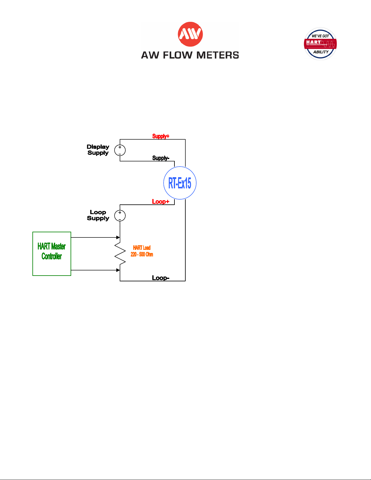
Connections for Single Node
1. RT-Ex15 Display unit requires a
24Vdc supply. See RT-Ex15 manual.
2. A second DC Voltage supply is
required to maintain HART Loop
Isolation from the RT-Ex15 display.
Voltage range is 12 to 24Vdc.
3. A load resistor is required in the
HART Loop. This load resistor may
be internal to the Master Controller.
Minimum value is 220 Ohms.
Maximum is 500 Ohms.
HART Protocol Overview
LEADING COMMUNICATION TECHNOLOGY
The HART Protocol is the leading communication technology used with smart process instrumentation today. The
HART Protocol continues to grow in popularity and recognition in the industry as a global standard for smart instrument
communication. More than two-thirds of all smart instruments shipping today communicate using the HART Protocol.
EASY TO USE
HART is field-proven, easy to use and provides highly capable two-way digital communication simultaneously with the
4-20mA analog signaling used by traditional instrumentation equipment.
UNIQUE COMMUNICATION SOLUTION
Unlike other digital communication technologies, the HART Protocol provides a unique communication solution that is
backward compatible with the installed base of instrumentation in use today. This backward compatibility ensures that
investments in existing cabling and current control strategies will remain secure well into the future.
Designed to compliment traditional 4-20mA analog signaling, the HART Protocol supports two way digital
communications for process measurement and control devices. Applications include remote process variable
interrogation, cyclical access to process data, parameter setting and diagnostics.
For more information see the HART Communication Foundations website:
www.hartcomm.org
Page - 1
HART Command Summary A
AW
Company
RTEX15
Summary
Universal
Command
Nbr
Function
0
Read Unique
Identifier
1 Read Primary
Variable
2 Read Current and
Percent of Range
b Bit-Mapped Flags
D Data (3 bytes: day, month, year-1900
F
H Integers
bF Bit Field
Data in
Command Data in Reply Notes
Byte Type Function Byte Type Value Function Detail
none 0 B Expansion code "254" ==
1-2 U16 E083 16-bit Device
3 B 3 Number of
4 B 7 Universal
5 B 10 Transmitter
6 B 10 Software Rev 10 --> 1.0
7 B 1 Hardware Rev &
8 B 0 Device Function
9-11 U24 tbd Device ID
12 B 3 Min. number of
13 B 0 Max. number of
14-15 U16 Configuration
16-17 U16 6002 16-bit
18-19 b 0 16-bit Extended
none 0 B PV Units Code see "Unit Code"
1-4 F Primary Variable Rate A PL
none 0-3 F Current (mA)
4-7 F Percent of
ASCII string (packed 4 characters per 3
bytes)
Floating Point (4 bytes IEEE
754)
expanded
command
Code
Preambles
Command
Revison
Specific
Command Rev
Signaling Code
Flags
Number
Slave preambles
Device Variables
Chang Counter
Manufacturers
Code
Field Device
Status
Range
Was 1 byte Mfg
Code + 1 byte
Device type for
HART 5 & 6
7 is not
required even
though rest of
commands
adhere to
HART 6.3
10 --> 1.0
same as on RTEx15 Faceplate
16-bit
increments with
each
configuration
change
see Common
Table 17
Tab
Page - 2
HART Command Summary A ASCII string (packed 4 characters per 3 bytes)
AW Company b Bit-Mapped Flags
RTEX15 D Data (3 bytes: day, month, year-1900
Summary F
H Integers
bF Bit Field
Universal
Command
Nbr
Function
0
Read Unique
Identifier
1 Read Primary
Variable
2 Read Current and
Percent of Range
Data in
Command Data in Reply Notes
Byte Type Function Byte Type Value Function Detail
none 0 B Expansion code "254" ==
1-2 U16 E083 16-bit Device
3 B 3 Number of
4 B 7 Universal
5 B 10 Transmitter
6 B 10 Software Rev 10 --> 1.0
7 B 1 Hardware Rev
8 B 0 Device
9-11 U24 tbd Device ID
12 B 3 Min. number of
13 B 0 Max. number of
14-15 U16 Configuration
16-17 U16 6002 16-bit
18-19 b 0 16-bit Extended
none 0 B PV Units Code see "Unit Code"
1-4 F Primary
none 0-3 F Current (mA)
4-7 F Percent of
Floating Point (4 bytes IEEE
754)
expanded
command
Code
Preambles
Command
Revison
Specific
Command Rev
& Signaling
Code
Function Flags
Number
Slave
preambles
Device
Variables
Chang Counter
Manufacturers
Code
Field Device
Status
Variable
Range
Was 1 byte Mfg
Code + 1 byte
Device type for
HART 5 & 6
7 is not
required even
though rest of
commands
adhere to
HART 6.3
10 --> 1.0
same as on RTEx15 Faceplate
16-bit
increments with
each
configuration
change
see Common
Table 17
Tab
Rate A PL
Page - 3
 Loading...