

AW-Lake RT-Ex15 Operating Manual
FLOW
ELECTRONICS FOR
TRANSMITTERS
R
R
FFLLO
T--
T
O
W
W
Users Manual
E
E
M
M
O
O
x
x
1
1
NIITT
N
5
5
O
R
O
R
INSTRUMENTATION
8809 Industrial Drive, Franksville, WI 53126-9337
Tel: 262-884-9800 Fax: 262-884-9810
E-Mail: aw@awcompany.com Web: http://www.awcompany.com

RT-Ex15 FLOW MONITOR
Introduction / Features…..………..……………………... page 2
Model Number/Sensor Options.……………………..….. page 2
Specifications…..………..…………………………..….. page 2
Dimensional Drawing.….………………………………. page 2
Wiring Connections……….................…………………. page 3
DC Power Connection...........…………………... page 3
Reset Input……….................…………………... page 3
Limits/Pulse Output...............…………………... page 3
Analog Output……................…………………... page 4
Frequency Input (Calibration) Test Point.………. page 4
Display/Programming Buttons and Magnetic Switches… page 5
Disable External Programming....………………. page 5
Programming the RT-Ex15..…………….....…..……….. page 6
Startup Message…………...........………………. page 6
RT-Ex15 Display Modes………………….....…..……….. page 6
LOGO Mode – Turning On/Off Displays……..... page 7
RATE Display Modes..............………………….. page 8
RATE A
RATE A PL .……................……………… page 8
RATE Mode Programming.............…………….. page 9
KFR A VALUE.................……………… page 9
GATE A B……..………….……………. page 10
SAMPLE A……………………………… page 10
ENG UNITS A……………………...…... page 10
TOTAL Display Modes.....…………………..…. page 11
TOTAL A Display…….……….….……. page 11
GR TOTAL A Display…….……...……. page 11
TOTAL Reset / Rollover…….…….……. page 11
TOTAL Mode Programming........................…… page 12
KFT A VALUE.…........…………….….. page 12
ENG UNITS A...….…..………………… page 13
STATUS ONE Display Mode.….……………... page 13
ANALOG OUT Display Mode.….……………... page 13
ANALOG OUT Programming.………………… page 13
MA OFFSET.…........………………..…. page 14
ANALOG POINT....…..………………... Page 14
VALUE AT 20 MA……………………… Page 14
LIMITS Display Mode...........…….……….……. page 15
LIMITS Programming…………………………… Page 15
RATE/TOTAL limits……...…………….. Page 15
CYCLE OUT (Totalizer Pulse Output)…. Page 15
RATE & TOTAL Display Mode ....…………….. page 16
BATCH TOTAL Display Mode ....…………….. page 17
BATCH TOTAL Programming.......…………….. page 17
QUICK-GUIDE to the RT-Ex15 Variables & Displays... page 18
Limited Warranty Statement.............…………………… page 19
GT
.……................……………… page 8
1
AW Company 8809 Industrial Drive, Franksville, WI 53126 à web: www.awcompany.com
Tel: 262-884-9800 Fax: 262-884-9810 | Email: aw@awcompany.com
RT-Ex15 manual.doc Revision 031507
2
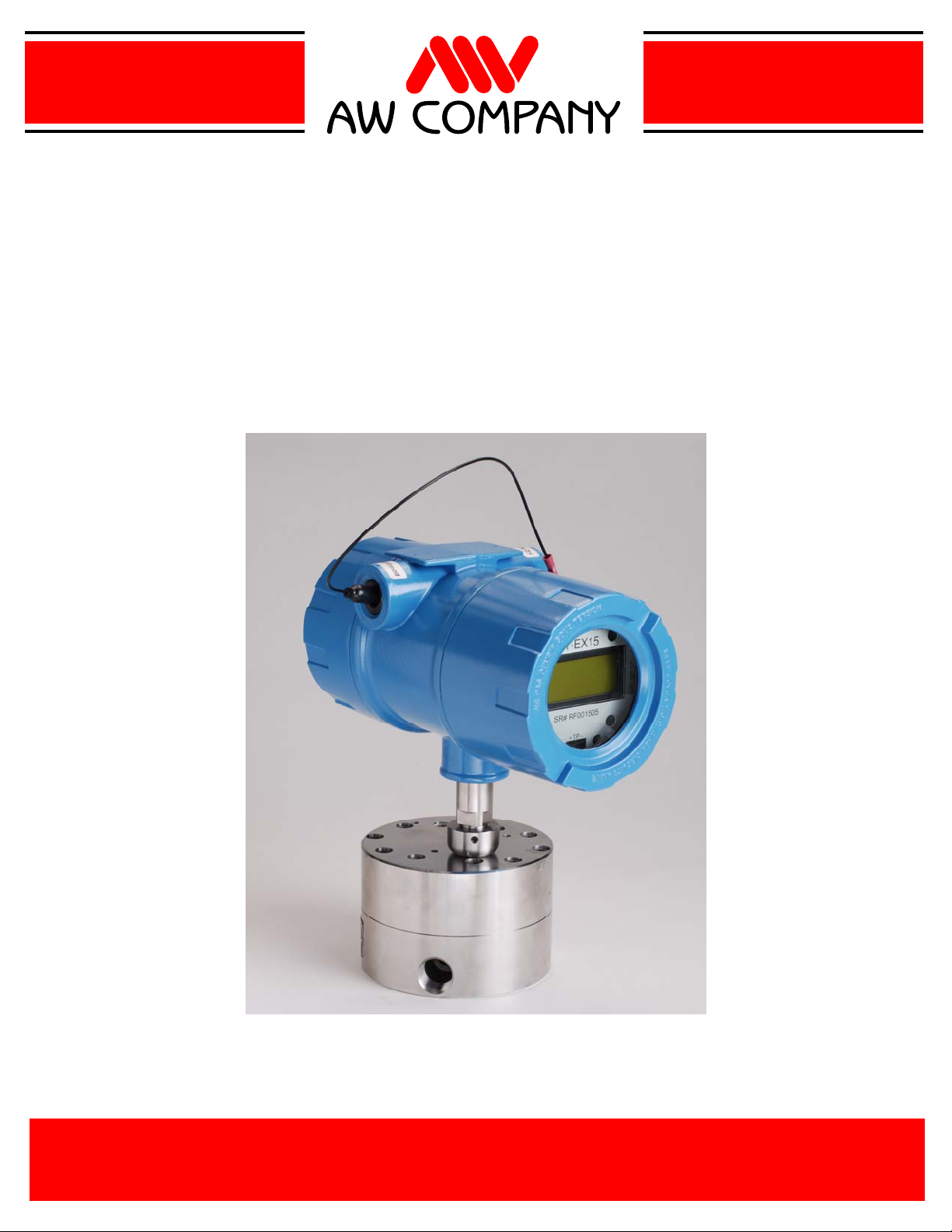
Introduction / Features
The RT-Ex15 is a meter-mounted digital flow monitor housed in a Class I Div. 1 Rated
Enclosure. A large, back-lighted LCD graphic display provides easy to read indication of
flow rate or total in user programmable engineering units. Programming, display mode
selection or reset of the totalizer are accomplished using an attached magnet without opening
the enclosure or using the pushbuttons on the faceplate with cover off. An isolated input also
allows for remote reset of the totalizer. Programmable opto-isolated NPN open-collector
outputs provide flowrate limit indication or a pulsed total output for remote monitoring and
recording of totals. A 4-20 mA rate output with user programmable filtering and scaling is
also provided for remote indication. A variety of sensor noses are available to provide
compatibility with all AW Company flowmeters.
RT-Ex15 Model/Sensor options:
RT-Ex15A MAG-PB sensor (standard) for JV-CG/KG, HPM & TRG series flowmeters.
RT-Ex15B IR-PB sensor for JVK series flowmeters.
RT-Ex15C
CP-30 high temp sensor (to 350ºF) for JVM-CG/KG, JVS-CG/KG HPM series meters.
RT-Ex15D MG-300 sensor for TR series turbine flowmeters.
Specifications
Power Requirement:
15-24 VDC/200mA. (customer supplied)
Sensor/Monitor Frequency Range:
0-4000 Hz.
Analog Output 4-20 mA:
16-bit Isolated Loop Powered 2-Wire Output.
12-27 Vdc Loop Supply
Max. Load Impedance 500 Ohm.@ 27V
Max. Load Impedance 250 Ohm.@ 12V
Two Opto-Isolated Open-Collector Outputs:
5-30 VDC Rating, 50 mA Max. (Minimum Load
Impedance Required, 600 Ohm @ 30 VDC)
Opto-Isolated Reset Input:
5-30 VDC Input, 3.3Kohm Impedance
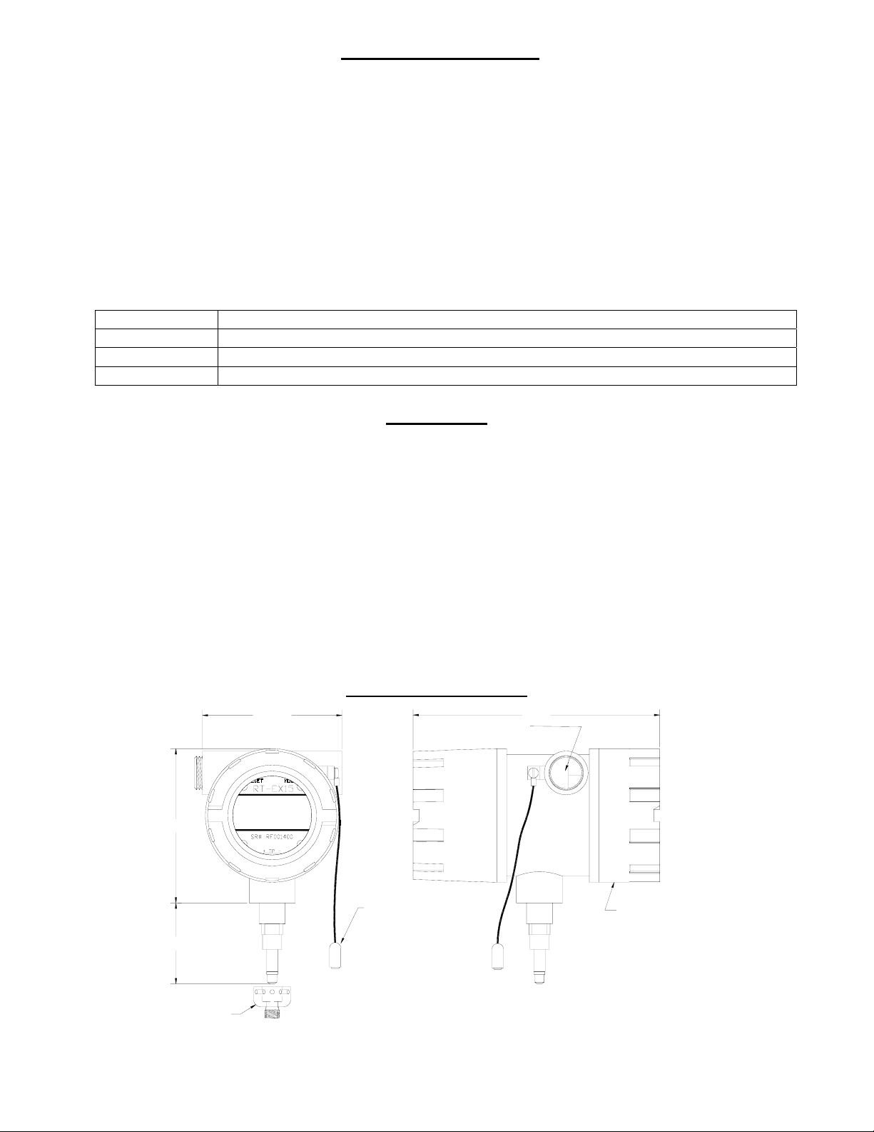
RT-Ex15 Dimensions
4.5 in.
Temperature Ratings:
-20 to 60ºC (-4 to 140ºF) Ambient
85ºC (185ºF) Max. Fluid Temperature (standard)
175ºC (350ºF) Max. Fluid Temperature (RT-Ex15C)
Enclosure Certifications:
Class I, Groups B, C, D
Class II, Groups E, F, G
Class III
Atex: EEx d IIC, IP68
NEMA 4X, 7BCD, 9EFG
Connection:
Screw terminal strips
¾" NPT Conduit Entrance
3/4" NPT WIRE
EN TRANCE
8 in.
5 in.
RA 002.50
TA 003.23
GPD
GAL
GT
MAGNET
WAND FOR
2.6 in.*
SW IVEL
FITTING
* WITH MAG-PB
SENSOR.
PROG RA M MIN G /
RESET/
DISPLAY
SELECTION
WIRING
TERM INAL
COVER
AW Company 8809 Industrial Drive, Franksville, WI 53126 à web: www.awcompany.com
Tel: 262-884-9800 Fax: 262-884-9810 | Email: aw@awcompany.com
RT-Ex15 manual.doc Revision 031507
3
Wiring Connections
Wiring connections are to terminal strips inside the rear cover. A ¾” NPT wire exit for conduit
connection is provided. Connection to conduit is required to maintain the enclosures explosionproof rating and must be made in accordance with all local and national electrical codes. TO
PREVENT IGNITION OF HAZARDOUS ATMOSPHERES, DISCONNECT CIRCUITS
BEFORE REMOVING COVER. KEEP COVER TIGHTLY CLOSED WHILE
CIRCUITS ARE ALIVE.
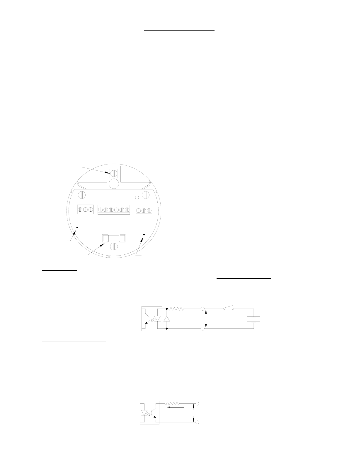
DC Power Connection
The RT-Ex15 requires a 15-24 VDC/200mA supply for operation. NOTE: A power supply is
still required to operate the RT-Ex15 even if the analog output is used in a loop-powered
configuration. The RT-Ex15 is internally isolated from the DC supply by a DC/DC converter. A
power-on LED is provided on the connection board and a 2 Amp mini-fuse protects the circuitry
in case of a supply fault. (See drawing below).
EN CL O S U R E
GROUND
TERM INAL
POWER
LED
2A MINI-FUSE
Reset Input
Opto-isolated input to reset the TOTAL A (Job Total). See TOTAL A RESET on page 11 for
information regarding reset of the job totalizer.
Limits/Pulse Outputs
Two opto-isolated NPN open-collector outputs can sink or source depending on connection.
Attention must be paid to polarity of connections, collector (+), emitter (-). See diagram below.
Output ratings are listed on page 2. Either output can be assigned to a rate limit, total limit for
batching or as a totalizer pulsed output. See LIMITS Display Mode
on page 15 for information regarding the display and programming of the limit and pulse output.
WIRING TERMINALS
(UNDER REAR C O VER)
C U STO MER C O NN ECTIO N S
(LEFT TO R IGH T)
15- 2 4/DC SUPPLY +Vdc Su p p ly
SUPPLY NEGATIVE -Vdc Su p p ly
EARTH G RO U N D (No t U s e d , u s e En cl. Gn d Te rm .)
RES ET + O ptically is olat ed input (+ )
RES ET - O ptically is olat ed input (- )
LIM IT1 + Optically isolated output (+)
LE1
15-24V/DC SUPPLY
RESET+
RESET-
LIMIT1 +
LIMIT1 -
LIMIT2 +
EARTH GROUND
SUPPLY NEGATIVE
F2
LIMIT2 -
Z00257 ver 1.2
JUL 2005 aw
LOOP -
LOOP +
+Vcc
LE2
mA OUT
LED
RESET IN PUT
LIM IT1 - Op tically isolated output (- )
LIM IT2 + Optically isolated output (+)
LIM IT2 - Op tically isolated output (- )
+ Vcc Supply Output (same as DC Supply)
LOOP + Isolated mA Loop (+ )
LOOP - Isola te d mA Loop (-)
(Isolated)
3.3 Kohm
RESET +
5-30VDC
Momentary
+
RESET -
and LIMITS Programming
LIM IT OUTPUTS
(Isolated)
100 Ohm
50 m A M ax.
AW Company 8809 Industrial Drive, Franksville, WI 53126 à web: www.awcompany.com
Tel: 262-884-9800 Fax: 262-884-9810 | Email: aw@awcompany.com
RT-Ex15 manual.doc Revision 031507
LIMIT (+ )
(Collect or )
5-30VDC
LIMIT (- )
(Em itter)
4
Analog Output
The isolated 16-bit 4-20mA output can be wired in a 2-wire loop-powered arrangement or loop
power can be supplied via the DC supply as shown in the wiring examples below. NOTE: A
separate power supply is required to operate the RT-Ex15 even if the analog output is used
in a loop-powered configuration. The mA LED will light with varying intensity in proportion
to the mA output for troubleshooting purposes. The assignment, offset, and scaling values for the
mA output are programmable. See ANALOG OUT Programming
on page 13 for information
regarding set-up of the analog output.
mA LOOP OUTPUT (2-WIRE, Isolated)
N O TE : S e pe rate s upp ly v o lt ag e s t ill r equir ed
for RT- Ex15 operation.
LOOP +
V loop
AD421
LOOP -
R sense = 250 Ohm max. @ 12-15 Vdc
R sense = 500 Ohm max. @ 15-27 Vdc
R sens e
+
12-27 Vdc
(Loop Power from RT- Ex15 DC Supply)
AD421
SUPPL Y NEG A TIVE
R sense = 250 Ohm m ax. @ 15 Vdc
R sense = 500 Ohm m ax. @ 24 Vdc
mA OUTPUT (3-WIRE)
+Vcc
LOOP +
mA LEDmA LED
LOOP -
+-
R sens e
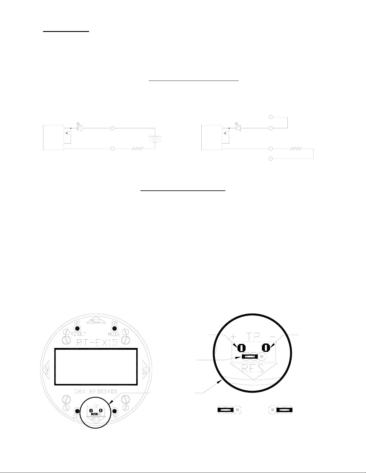
Frequency Input Test Point
The RT-Ex15 has a frequency input test point allowing the user to directly input a frequency
signal. This is especially useful for purposes of setting up and testing pulse output or analog
output signals during commissioning when flow is not present or where it is not feasible to allow
continuous flow for set-up and calibration purposes. The position of a programmable jumper
must be changed to allow use of the test point input. The test points and jumper positions are
detailed in the diagram below. Be certain to change the jumper back to the correct position
before beginning normal operation using the sensor nose.
Test Point input specifications:
Waveform: DC signal - pulse, square-wave, triangle, or sawtooth.
Minimum signal amplitude: 2 Volts peak.
Maximum signal amplitude: 10 Volts peak.
Frequency: 0-4000Hz
RA 002.50
TA 003.23
GT
GPD
GAL
Te s t Po int (+ )
(Sig n al In put )
Pro gr a m
Jumpe r
Te s t Po int (- )
(Isolated
Supply
Com m on)
CALIBRATION
TEST PO INTS
& JUMPER
JUM PER S ETTING S
123 123
Norm al
Operation
Jum p 1 & 2
Te s t Point
Operation
Jum p 2 & 3
AW Company 8809 Industrial Drive, Franksville, WI 53126 à web: www.awcompany.com
Tel: 262-884-9800 Fax: 262-884-9810 | Email: aw@awcompany.com
RT-Ex15 manual.doc Revision 031507
Display/Programming Buttons and Magnetic Switches
Display mode changes, reset of total and programming functions are accomplished using the
buttons located on the face plate when the cover is off or external to the cover using the magnetic
switches. The magnetic switches are located at the 3, 6, 9 and 12 o’clock positions on the side of
the housing. The function of each position is indicated on the faceplate of the RT-Ex15.
Touching the side of the magnet wand to the appropriate location will activate the magnetic
switches.
DISPLAY/PROGRAM MING
B U TTO N LOCA TIONS
RESET/UP
BU TTON
MAGNETIC
SWITCH (MOD E/DN)
MODE/DN
BU TTON
MAGNETIC
SWITCH
(ENT)
RA 002.50
TA 003.23
GPD
GAL
GT
MAGNETIC
SWITCH
(SEL)
EN T
SEL
BU TTON
MAGNETIC
SW ITC H (RESET/UP)
ENT
BU TTON
Display mode changes, reset of total and programming functions are accomplished using the
buttons located on the face plate when the cover is off or external to the cover using the magnetic
switches. The magnetic switches are located at the 3, 6, 9 and 12 o’clock positions on the side of
the housing. The function of each position is indicated on the faceplate of the RT-Ex15.
Touching the side of the magnet wand to the appropriate location will activate the magnetic
switches.
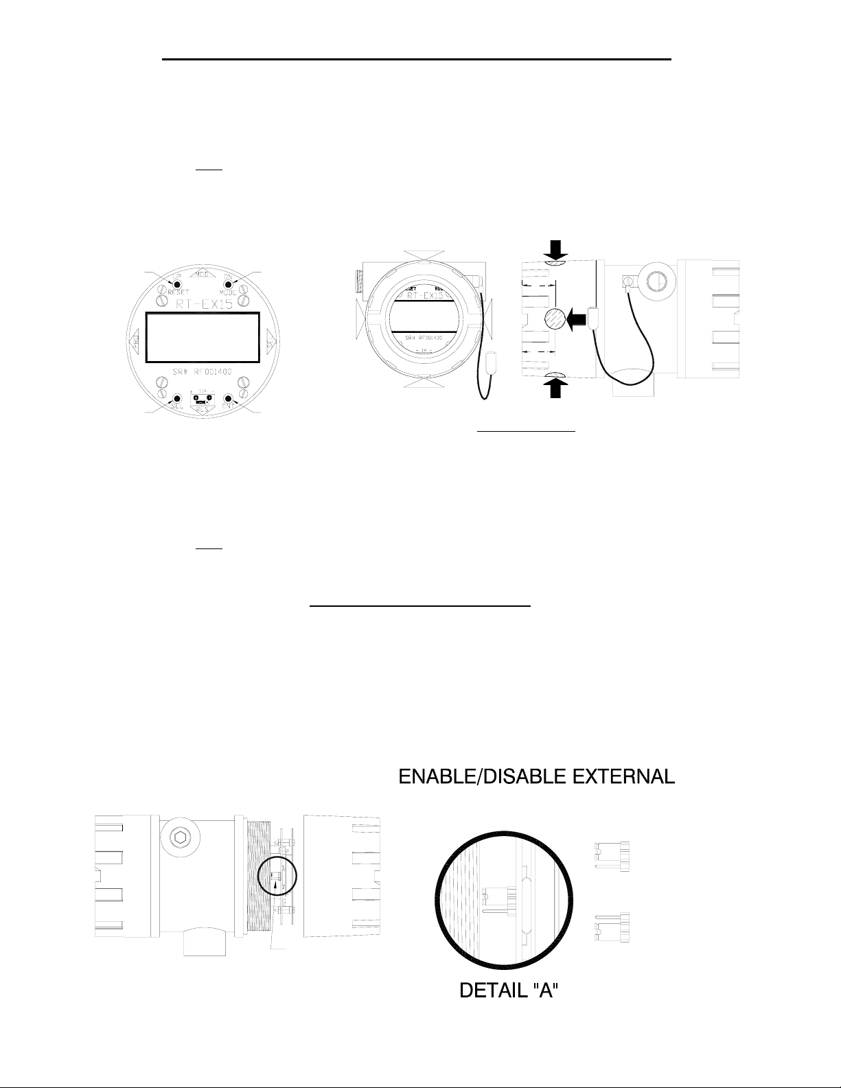
Disable External Programming
All programming is initiated by using the ENT button located on the face plate when the cover is
off or external to the cover using the ENT magnetic switch when the cover is installed. The ENT
external magnetic switch can be disabled to prevent programming when the cover is on. A
jumper is located on the back of the main circuit board on the edge at the 9 o’clock position. If
the jumper is set to disable the ENT magnetic switch, the MODE and RESET external magnetic
switches are still active to allow mode changes and total reset but program changes can not be
made without removing the cover and using the ENT button on the faceplate. The default is
switch enabled.
MAG NET IC SW ITCH L OC ATIO NS
DN/
MODE
1
1
4
RA 002.50
TA 003.23
RESET
GT
GPD
GAL
UP/
TOUCH SIDE OF MAGN ET TO SWITCH LOCATION
SEL
1
1
4
5
PROGRAMMING
"ENT" MAGNETIC
1
SWITCH ENABLED
2
3
JUMP 1 & 2
"ENT" MAGNETIC
1
2
SWITCH DISABLED
3
ENABLE/DISABLE EXTERNAL
PROGRAMMING JUMPER ON BACK
OF MAIN CIRCUIT BOARD AT THE
EDGE IN 9 O'CLOCK POSITION
(SEE DETAIL "A")
AW Company 8809 Industrial Drive, Franksville, WI 53126 à web: www.awcompany.com
Tel: 262-884-9800 Fax: 262-884-9810 | Email: aw@awcompany.com
RT-Ex15 manual.doc Revision 031507
JUMP 2 & 3
 Loading...