

COMPANY
Positive Displacement Gear Meters
Installation, Operating &
Maintenance Manual
©2016 AW-Lake Company. All rights reserved. Doc ID:POSDISMAN082416

Table of Contents
Safety Denitions and Information ................................................................ 3
Unpacking .............................................................................................................. 3
Quick Start ............................................................................................................ 3
Install Pickup Sensor ............................................................................................. 3
Flush Piping ............................................................................................................ 3
Filtration .................................................................................................................. 3
Location ................................................................................................................... 4
Orientation ............................................................................................................. 4
Flow Direction......................................................................................................... 5
Product Description and Principle of Operation .......................................... 5
Filtration .................................................................................................................. 5
Installation ............................................................................................................ 5
Preferred Flow Direction ....................................................................................... 5
Preferred Orientation ............................................................................................ 6
Location ................................................................................................................... 6
Installing a Bypass ................................................................................................. 6
Pickup Sensor ......................................................................................................... 6
Location ................................................................................................................... 7
Installation .............................................................................................................. 7
Operation .............................................................................................................. 8
Overview ................................................................................................................. 8
Running the Flow meter ........................................................................................ 8
Ramp Up ................................................................................................................. 8
Regular Cleaning .................................................................................................... 8
End of Shift and Overnight Preparations ............................................................ 9
Breakdown .............................................................................................................. 9
Plugging ................................................................................................................... 9
Filtration .................................................................................................................. 10
Maintenance ......................................................................................................... 10
Use the Maintenance Guides ............................................................................... 10
Flow Testing ............................................................................................................ 10
Plugging and Filtration .......................................................................................... 10
Calibration .............................................................................................................. 11
Storage .................................................................................................................... 11
Flow Meter Do’s and Don’ts ............................................................................... 11
Calibrations ........................................................................................................... 12
If ow readings are too high ................................................................................. 12
If ow readings are too low .................................................................................. 13
If it is necessary to adjust the existing k-factor .................................................. 13
If it is necessary to re-calculate a new k-factor .................................................. 13
Trouble-Shooting Guide ..................................................................................... 14
2

Safety Denitions and Information
Do not attempt to install or use your AW Gear Meters product until you have read
the safety instructions in this section. Save this manual and keep it in an easily
accessible place.
Unpacking
Separate the flow meter from packaging materials and check for any visual
signs of damage. If you determine there has been damage caused by shipping,
file a claim with the shipping company. If the flow meter appears to have
been improperly assembled or does not operate properly, return the product
for replacement or repair (see Limited Warranty information at the end of this
manual).
Quick Start
To set up, install and operate your flow meter quickly, follow these step-by-step
instructions. Detailed installation, operational, and maintenance instructions begin
on page 5 in this manual. More information is also available in the Maintenance
Guide appropriate for your flow meter.
Install Pickup Sensor
Before attaching the sensor to the flow meter, check for any potential clearance
issues. It may be easier to install the sensor after you have installed the flow
meter in the line.
CAUTION: Whether the sensor requires tool or hand installation, tighten with
hand-tighten torque only.
NOTICE: Some ow meters are shipped with the sensor already installed.
Flush Piping
If feasible, flush piping to remove dirt and debris before installing flow meter.
Filtration
Filtration is recommended to prevent contaminants from entering the flow meter.
3
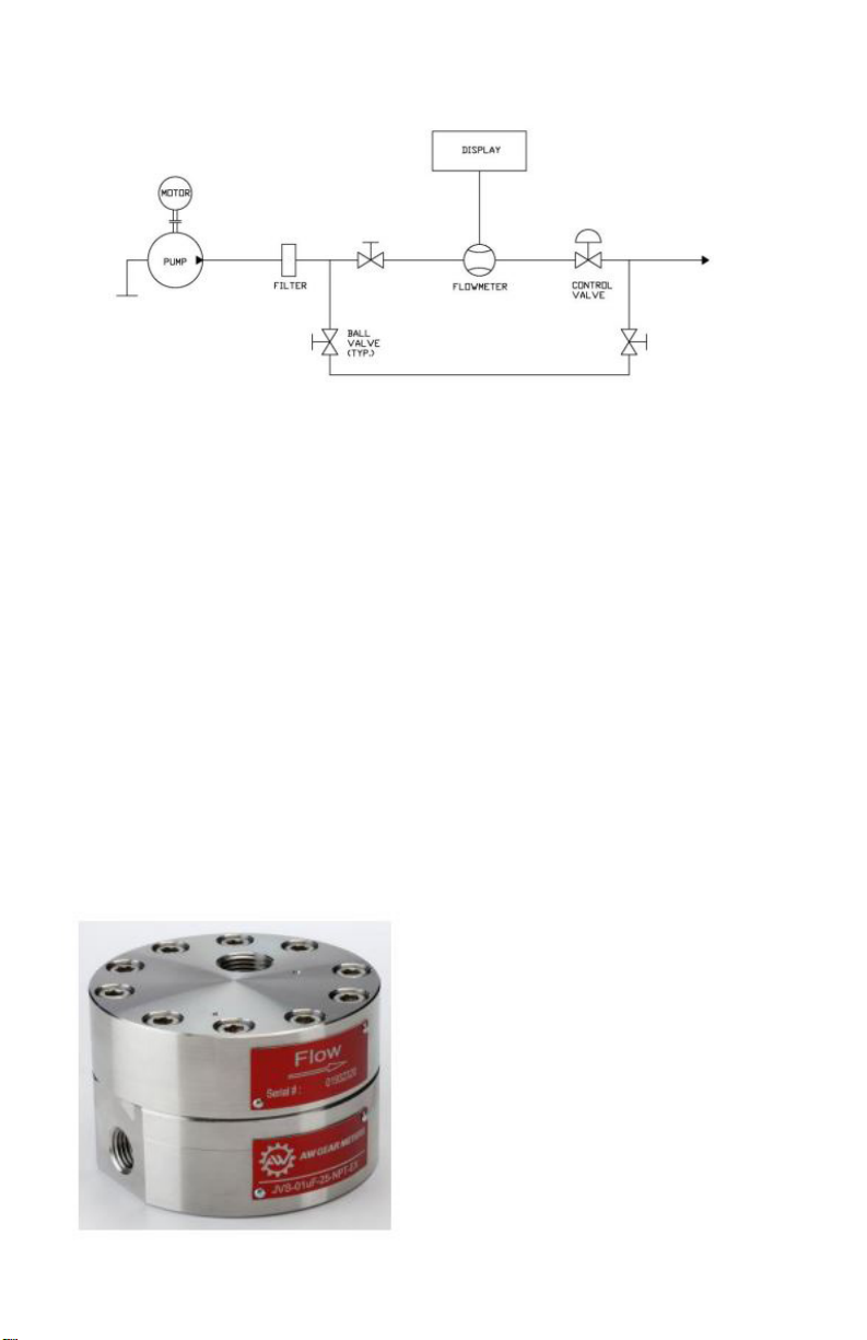
Figure 1: Typical flow meter installation with bypass
See flow meter Data Sheet for specific filter, including mesh weight and size.
Location
It’s best to install the flow meter upstream from control valves and fluid
regulators, if possible. See Figure 1.
Orientation
Positive displacement gear flow meters can be installed either a horizontal or
vertical (flow up) orientation. 2-3 psi of backpressure is required to assure
the meter is always full of fluid. No straight run pipe is required upstream or
downstream of the meter.
Figure 2: Flow meter with direction of low marked with arrow
4

Flow Direction
Flow direction is marked with an arrow on the flow meter. See Figure 2.
Product Description and Principle of
Operation
AW Gear Meters positive displacement gear flow meters are similar in design to
the gear pump. However, the principle of operation is reversed: instead of the
gears driving the medium, the medium drives the gears. A non-intrusive sensor
detects the movement of the gear. As each tooth passes the sensor, the sensor
produces a square-wave pulse and measures a discrete volume of liquid. The
resulting pulse train is proportional to the actual flow rate, providing a highly
accurate representation of the fluid flow. All flow meters are designed with
highly wear-resistant moving parts to provide exceptionally long service life. The
materials of construction are:
• stainless steel or high-strength aluminum housing
• stainless steel gears
• either tungsten carbide sleeve bushings or stainless steel ball bearings
(depending on model)
The fluids you are metering should be compatible with these materials.
Filtration
Filtration depends on the model. Make sure to follow proper filtration requirements
for your specific model. Because the internal assembly has very small
clearances, small filter sizes are required, especially for ball-bearing flowmeter
versions.
NOTE: Filters are meant to lter out impuries in the uid stream. If you are measuring uids with
llers, even if the llers are smaller than the maximum recommended lter size, please consult the
factory for correct meter selecon.
Installation
Preferred Flow Direction
The preferred flow direction is marked with an arrow on the meter showing the
flow direction in which the flow meter was calibrated (see figure 2). However,
5

the flow meters have bi-directional flow capabilities and are often used for bidirectional flow applications. Since the meters indicate flow in both directions,
if reverse flow detection is not desired, install a check valve up-stream of the
flowmeter.
Preferred Orientation
The preferred orientation for mounting gear meters, especially in low flow and
or low viscosity applications, is so that the internal shaft/gear assembly is in a
horizontal orientation (housing bolts facing sideways, not up/down). This allows
for the least amount of internal drag due to mass of gears.
Location
It is important to make sure that the flowmeter is always full of fluid and never
partially filled. Do this by making sure there is always a small amount of
backpressure on the meter, usually 2 to 5 psi minimum.
Create backpressure by making sure there is some flow restriction downstream
from the flowmeter such as a check valve, regulator, or piping rising above
location of flowmeter. See Figure 1.
Backpressure from control valving is beneficial for stable running. In similar
fashion, if a flowmeter is installed with fluid flow in a downward direction, the fluid
cannot exit the flowmeter directly into a container with no restriction due to the
fact the meter will not be full of fluid, causing inaccurate measurement.
CAUTION: Eliminate all dirt, debris and metal shavings from the piping, as
the liquid must be free from any particles larger than what the manufacturer’s
specifications allow. Install any recommended filtration before operation, as
potential plugging most often occurs at startup.
Installing a Bypass
If possible, install a bypass around the flow meter, and flush existing piping with
the appropriate liquid before first use. See Figure 1.
Pickup Sensor
Review the pickup instructional guide prior to installation.
6

Location
Locate the pickup and wiring away from A/C motors, actuators, heaters, relays,
etc. Use only shielded cable and if possible, a dedicated power supply for the
electronics. If sharing power with other devices in the system, be aware that
power-draw spikes from other equipment could cause a surge into the sensor,
which in turn can cause sensor to give erroneous pulses. Ensure clean power
supplies that utilize a true earth ground. Install Intrinsic Safety Barriers if the
circuit is intended to be intrinsically safe.
Installation
Before attaching the sensor to the flow meter, check for any potential clearance
issues. It may be easier to install the sensor after the flow meter has been
installed in the line.
CAUTION: Do not use a wrench or Channellock®* to aid in hand installing the
pickup sensor.
CAUTION: Whether the sensor requires a tool to install or is hand installed,
tighten to hand-tighten torque only. Over tightening may cause damage to the
sensor and as a result it may not function properly.
Figure 3: Flow meter with pickup sensor installed
*Channellock® is a registered trademark of Channellock, Inc.
7

Operation
CAUTION: Before installing, operating or attempting maintenance on a flow
meter, read the appropriate Maintenance Guide. As with any precisionengineered device, always operate and maintain the equipment in
accordance with the manufacturer’s instructions.
Overview
Flow meters are designed to measure the flow of liquids, which assist in
cooling and lubrication. Always close meters to air except when air is part of
an automated purge cycle, such as certain paint systems. In this case, the air
segments are typically under 1 or 2 seconds and are interspersed with lubrication
liquid for a scrubbing effect; in addition, the air segments are short enough that
the flow meter does not dry out.
CAUTION: Do not dry lines using only pressurized air, as this will lead to
premature wear.
Running the Flow meter
Never run the flow meter dry or spin with air only. Gear flow meters are
precision-engineered flow devices. Always maintain them in a clean, lubricated
condition with the internal parts wet at all times. Do not allow air or water to
contact the internal parts except in short (1-2 second) cycles as part of an
automated flush. If you flush meter with water, make sure to run non-corroding
fluid through the meter afterwards. Even stainless steel meters will stain or
corrode from the minerals in most water.
Ramp Up
Do not increase flow to a full flow condition instantaneously. Gear flow meters are
rugged yet precise instruments that respond almost instantaneously to changes in
fluid flow. To avoid damage to the system, increase flow to maximum over a few
seconds rather than instantaneously and do not inject high flow speeds into an
empty flow meter.
Regular Cleaning
Designing and maintaining a flush procedure that keeps the flow meter internals
clean and wet is critical to optimum performance and minimum maintenance.
Cleaning cycles vary due to the differences in coatings, equipment, and cleaning
fluids, and some testing may be prudent to determine the most efficient method.
8

More corrosive fluids may also require more frequency flush cycles, or if meter
sits idle for longer periods of time, such as between shifts, flushing may also
be required more often. Consult with the fluid manufacturer for recommended
cleaning fluids.
NOTE: During line shutdowns such as overnight and over weekends, ush and leave meters lled
with proper cleaning uid under pressure to allow any residue that may have built up to soak and
dissolve.
End of Shift and Overnight Preparations
At the end of a shift or overnight, leave cleaning fluid in the flow meter under
pressure, to soak. This helps keep unflushed residual fluids from drying, and
facilitates subsequent startups. Opening a flow meter after a flush cycle helps
determine if the purge is thoroughly cleaning the flow meter.
Breakdown
NOTE: Full breakdown instrucons are included in the Maintenance Guide.
NOTE: If you remove a ow meter from the line during maintenance, do not allow uids to dry
inside. Clean the internals immediately, lubricate them, and cap the uid ports.
NOTE: Clean the carbide surfaces at the point where the gear rotates on the sha. Buildup here
may occur as a thin smear and may be dicult to see, but causes fricon and accelerate addional
buildup later when the gears are reinstalled. Spin the gears by hand to verify that they rotate freely
on the sha and apply a suitable lubricaon uid before closing the ow meter. Aer ghtening the
bolts, a short squirt of shop air will briey spin the gears, which should be easily audible.
CAUTION: Do not overspin gears if using shop air to verify free rotation of
gears prior to installation
.
CAUTION: Do not use wrenches or a Channellock to aid in re-installing the
pickup sensor by hand. Whether you are installing the sensor with a tool or by
hand, tighten to hand-tighten torque only.
Plugging
In the event of plugging, the flow meter passes a reduced volume of fluid with an
increased backpressure and no frequency output. Careful installation is important
because this is the time when contaminants such as tape or metal shavings can
enter the flow meter. Filters should be in line to prevent oversized particles from
entering the flow meter.
In the event the flow meter needs to be returned to the factory for further
evaluation, flush the flow meter in place and cap the ports. Pack carefully (with
9

original packing materials, if possible) prior to shipping to prevent damage.
Filtration
Filtration is recommended to prevent contaminants from entering the flow meter.
If the flow meter is plugged, a reduced flow can still be observed from the nozzle
or outlet, as fluid pressure squeezes fluid through the flow meter. Should this
occur, review the cleaning and maintenance procedures in the following sections.
Maintenance
Follow these general guidelines for operating and maintaining your positive
displacement flow meter.
Use the Maintenance Guides
Always review the Maintenance Guides provided with the flow meter
(download additional copies at www.awgearmeters.com ) prior to attempting
any maintenance work. The majority of down time and repairs is the result
of breakages due to improper maintenance actions, lack of training or rough
handling.
Flow Testing
Do not use water for flow testing. The viscosity of water is too low to produce
accurate results unless the flow rate is elevated, and the internals would then
have to be dried and lubricated to avoid corrosion or scaling. If system calibration
is necessary, the preferred calibration fluid is the actual fluid to be metered.
Alternatively, using a fluid with a viscosity of approximately 30 cSt° such as
mineral oil or thinned glycerin is recommended.
Plugging and Filtration
Filtration is recommended to prevent contaminants from entering the flow meter.
Should the flow meter become plugged, a reduced flow may still be observed
from the outlet as fluid pressure will squeeze fluid through the flow meter –
visual flow does not necessarily mean that the flow meter’s gears are turning.
If contaminants are causing the plugging, install filtering. If particle buildup
repeatedly causes plugging, review the cleaning and maintenance procedures in
the Regular Cleaning section on page 8. Because of the considerable differences
in fluid types and in-plant procedures, some trial and error may be required to
determine the ideal flushing or cleaning regimen.
*cSt is a unit of kinemac viscosity that equals one hundredth of a stoke.
10

Calibration
A calibration factor (k-factor) is established at the factory on a preferred
calibrating fluid. This number, which is provided with the flow meter either on a
Calibration Data Sheet or on a tag attached to the flow meter, is usually accurate
for a wide variety of fluids and should not usually be changed. Should the data
sheet become lost, contact the factory for a duplicate copy. See the Calibrations
section on page 12 for a calibration verification procedure.
Storage
When the flow meter is idle or stored for any extended period, perform the
following:
1. Clean the internals thoroughly with the appropriate fluid
2. Lubricate with a light oil or other non-corrosive fluid
3. Cap or plug the ports to prevent drying
Flow Meter Do’s and Don’ts
DO: Leave flushing fluid in the lines overnight or during extended off-times. This
keeps internals wet, prevents residual fluids from drying, and facilitates startups.
DO: Follow the Maintenance Guide instructions when opening and cleaning a flow
meter. During cleaning, separate the gears from the shafts. On carbide bearings,
clean inside the center of the gear bearing and on the outer surface of the shafts
at the point where the gear rotates on the shaft. Apply a suitable lubricating fluid
before closing the flow meter. After tightening the bolts, a short squirt of shop
air will briefly spin the gears, which should be easily audible.
DO: Install and maintain filters. Install the recommended filter to eliminate
potential plugging. Should plugging occur, the flow meter will still pass fluid but
with no signal output.
DO: Check electrical compatibility between the flow meter’s output signal and the
input of the PLC. If signals are not being detected at startup, first check wiring
and electrical compatibility.
DO: Verify reliable grounding of electrical parts, as per installation guidelines. A
dedicated power supply is recommended. Voltage spikes on shared power lines,
negligent grounding and sloppy wiring will likely produce erratic readings and
chronic maintenance.
11

DO: Install the flow meter immediately upstream of the regulator or control valve.
The control valve provides backpressure, which stabilizes the flow.
DON’T: Allow air into the flow meter. Always keep the flow meter internally wet.
DON’T: Dry lines using pressurized air. Flow meters are designed to flow liquids.
Close meters to air except when air is part of an automated purge cycle. Do not
dry lines after purging.
DON’T: Allow materials to dry inside the flow meter. When a flow meter is
removed from the line during maintenance, clean the internals immediately,
lubricate the gears, and cap the fluid ports.
DON’T: Over tighten the pick-up sensor beyond hand tight. When installing the
pickup sensor, turn it in lightly to a hand-tight torque. Do not use a wrench on
the pickup as over tightening may cause a dimple of metal under the sensor nose
to protrude into the gear cavity and interfere with the gear’s rotation.
DON’T: Use water or solvent for calibration or test purposes. Water or solvent
may not turn the gears at low flow and may leave the impression that the flow
meter is not functioning. A calibration factor (kfactor) is issued with the flow
meter, which is valid for most fluids except water or equivalent viscosities.
Calibrations
Each flow meter is calibrated and given a “k-factor” using a standard calibrating
fluid at the factory. This number is accurate for all fluids with most viscosities,
except the most water-like. There should be no need to change this except for
fluid viscosities below 30cSt.
If ow readings are too high
If the display shows significantly more than the volume actually dispensed or
shows flow when there is definitely no flow, this most likely indicates an electrical
noise problem. In such cases, turn off nearby motors, heaters or relays, check
cable shielding, and establish a clean ground independent of other electrical
devices before repeating accuracy tests. If the problem continues, it may be
necessary to relocate the offending device or reroute cabling away from noise
sources.
12

If ow readings are too low
If the display shows significantly less than the volume actually dispensed, most
likely the flow meter has a high slippage factor, and the fluid is bypassing the
gears and the k-factor may require adjustment. Dirt or dried material can also
keep gears from rotating freely.
If it is necessary to adjust the existing k-factor
Trigger at least 500ml of your sample fluid in a steady stream at approximately
the desired flow rate into a graduated beaker. Compare the volume in the beaker
to the volume on the display. Do not time the operation; merely measure the
volume dispensed. Repeat the sample 3 times and take an average. If the
result is outside an acceptable margin, adjust the k-factor by the percentage
of difference between the average beaker sample and the average displayed
total. If the error is not rectified, clean the flow meter thoroughly and repeat the
procedure. Do not use water for this test. For most accuracy results,
calibrate using fluid to be measured with flowmeter.
If it is necessary to re-calculate a new k-factor
You will first need a data-collecting instrument to count pulses produced by the
flow meter. An AW display may be used in totalizer mode provided the KFT is
set to count each pulse (KFT = 10000). Trigger at least 500ml of your sample
fluid in a steady stream at approximately the desired flow rate into a graduated
beaker.Divide the number of pulses by the volume dispensed and the result is
your new kfactor in the units of your sample. In the example above, the k-factor
units would be impulses/ml.
13

Trouble-Shooting Guide
14

15

COMPANY
414.574.4300 | www.aw-lake.com
2440 W. Corporate Preserve Dr. #600 Oak Creek, WI 53154
©2016 AW-Lake Company. All rights reserved. Doc ID:POSDISMAN082416
 Loading...