

AW-Lake JV-KG Maintenance Guide
MAINTENANCE GUIDE FOR THE JV-XXKG SERIES FLOW METER
Cleaning, inspecting or repairing a JV-KG Series gear flow meter is easily accomplished by following the
procedures below.
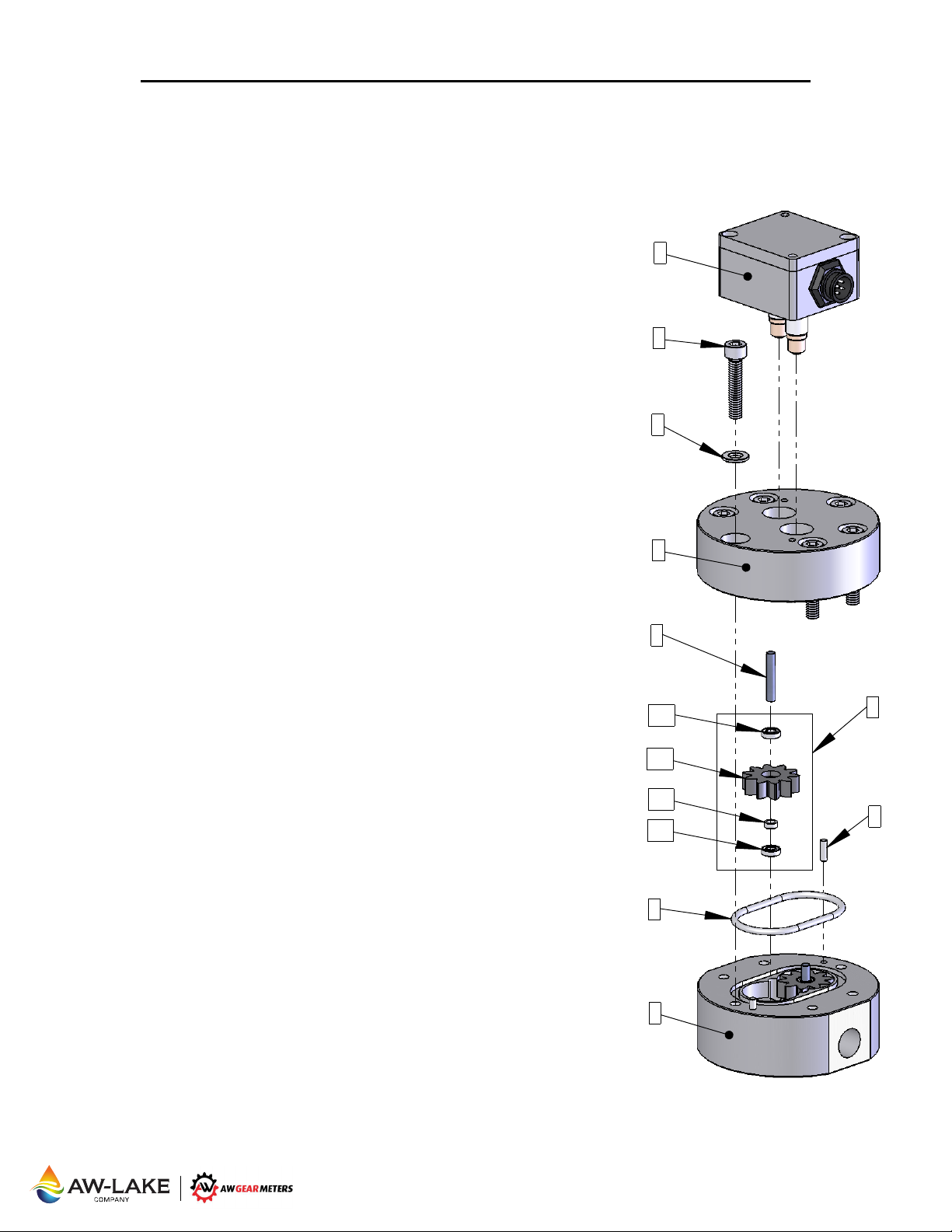
1. Remove the Sensor (1) from the flow meter body Upper Housing (4). Using a
3mm hex key, loosen the 2 mounting screws inside the sensor.
2. For the JV-30 size and smaller use M6 Bolts (2), loosen them using a 5mm hex
key. The JV-60 uses M10 Bolts (2), loosen them using an 8mm hex key. Keep
the 2 opposing bolts near the Locating Pins (7) engaged by a few threads to
avoid stress on the shaft
Please note the orientation of the Upper and Lower housings with respect
to each other so that the meter is reassembled the same way.
3. Holding the Upper Housing (4), gently tap on the top of the 2 opposing bolt
heads to separate the Upper Housing (4) from the Lower Housing (9). Do NOT
use chisels or screwdrivers to split and pry apart the housings. This can
cause damage to the meter bodies and meter internal parts.
4. After separation, remove, clean and inspect the gear assemblies (6) and shafts
(5). Clean out the o-rin
IMPORTANT: The gear assembly consists of two bearings (6a), the Gear
(6b), and a Bearing Spacer (6c. These parts are loosely fitted and can fall
out. These parts are matched together and careful attention MUST be
made to their orientation and location as they MUST be replaced the exact
way they were.
5. After cleaning all parts completely, the Gear Assemblies (6), Shafts (5) and
Locating Pins (7) can be reinserted. Check for free and easy rotation of the
gears.
6. Replace the O-Ring (8). PTFE o-rings s
can be reused if they are not damaged.
Note: JVx-60KG flow meters use 2 o-rings per meter.
7. During reassembly keep the meter housings as parallel as possible. Make sure
the housings are orientated the same way they were prior to disassembly.
8. Replace the Washers (3) and the Bolts (2). Torque the bolts to 15Nm for
the12, 20 and 30 size meters and 30Nm for the 60 size meters. Do not force
the meter housings together. Do NOT use a hammer or other such device.
ver tightening will not cause damage to the meter, but may fatigue the bolts
O
and/or restrict the operation if internal surfaces are not completely clean.
9. After reassembly, gently blow air through the meter so the gears spin. This
should be clearly audible given a moderate background noise level.
10. Clean any debris from the pickup holes before remounting the sensor (1) to the
Upper Housing (4). Use a 3mm hex key to tighten the mounting screws in the
sensor to mount the sensor on the housing. Note that there is a correc
incorrect orientation for the sensor to be mounted on the flow meter.
Please see the AW Gear Meters website for documentation if you do not have
it. The orientation is noted by the sensor’s connector with respect to the outlet
port of the flow meter.
s and the locating pins during housing separation.
g groove, shaft holes and meter cavity.
hould always be replaced. FKM o-rings
t and
1
2
3
4
5
6a
6b
6c
6a
8
6
7
9
JV-20KG w/ DH-B Shown
2440 W. Corporate Preserve Dr. #600, Oak Creek, WI 53154 | www.aw-lake.com | Rev. 07/2017
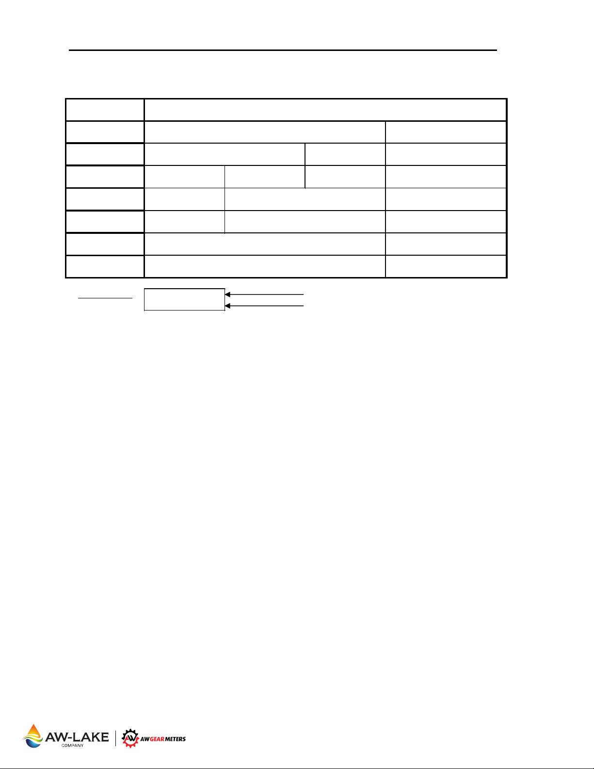
Table Format:
AG15030 AW Part #
ST-12KG Shaft
AG15060 - 6 pcs
AG15065 - 6 pcs
Part - Qty. per meter
AG15030
CROSS REFERENCE GUIDE FOR JV-XXKG SERIES SPARE PARTS
[Drawing Ref. #]
Locating Pin - 2
[7]
Shaft - 2
[5]
Gear Assembly - 2
[6]
PTFE O-Ring - 1
[8]
FKM O-Ring - 1
[8]
Bolts - 6
[2]
Washers - 6
[3]
JV-12KG JV-20KG JV-30KG
LP-CG Locating Pin
AG12015
AG12010 AG20040 AG30050 AG60070
GR-12KG GR-20KG GR-30KG GR-60KG
AG12020 AG60080 - 2 pcs
COT-12KG COT-60KG
AG12025 AG60085 - 2 pcs
COV-12KG COV-60KG
SC-M6x1-30mm - 6 pcs
Washer - M6 Hardened Washer
LP-CG Locating Pin AW Part Description
AG15040
COT-15CG
AG15045
COV-15CG
AG30055 AG60075
ST-30KG Shaft ST-60KG Shaft
JV-60KG
AG60030
LP-60CG Locating Pin
AG60050 - 12 pcs
M10x70mm
AG60055 - 12 pcs
Washer - M10 Hardened Washer
2440 W. Corporate Preserve Dr. #600, Oak Creek, WI 53154 | www.aw-lake.com | Rev. 07/2017
 Loading...