

Page 1

FEM-03
FLOW MONITOR
OperaƟon & InstallaƟon Manual
Rev. 2
Page 2

FEM-03 Flow Monitor
Operation and Programming Manual
Table of Contents
Safety Definitions and Information ............................................................................................................... 5
Unpacking ..................................................................................................................................................... 5
Quick Guide ................................................................................................................................................... 6
Connect to Sensor ..................................................................................................................................... 6
Connect to Power ..................................................................................................................................... 6
Basic Key Definitions ................................................................................................................................. 6
Programming and Data Entry.................................................................................................................... 6
Product Description ...................................................................................................................................... 7
Principle of Operation ............................................................................................................................... 7
Features .................................................................................................................................................... 8
Model Number Key ................................................................................................................................... 8
Technical Data ........................................................................................................................................... 8
Power Supply ........................................................................................................................................ 8
Flow Sensor Power Supplies ................................................................................................................. 8
Frequency Inputs .................................................................................................................................. 8
Analog Output 4-20 mA ........................................................................................................................ 9
Relay Contact Ratings ........................................................................................................................... 9
Dimensions ................................................................................................................................................ 9
Input and Output Wiring Connections ...................................................................................................... 9
Upper Connector Terminal Designations ............................................................................................ 10
Lower Connector Terminal Designations ............................................................................................ 11
Terms and Definitions ................................................................................................................................. 13
FEM-03 Start-Up Display Messages ............................................................................................................ 13
Display Modes ............................................................................................................................................. 14
LOGO – FEM-03xx Screen ....................................................................................................................... 14
RATE ........................................................................................................................................................ 14
Pulse Width Method ........................................................................................................................... 15
1
Page 3

FEM-03 Flow Monitor
Operation and Programming Manual
Gate Time Method .............................................................................................................................. 15
RATE A or B GT (RATE A or B Gate Time) .................................................................................................. 15
RATE A or B PL (RATE A or B Pulse Length) .............................................................................................. 15
Job or Grand Total Channel A or B .......................................................................................................... 16
TOTAL A or B RESET................................................................................................................................. 16
GR TOTAL A or B RESET ........................................................................................................................... 16
TOTAL and GR TOTAL Rollover ................................................................................................................ 16
STATUS ONE ............................................................................................................................................ 17
RATIO AB/RATIO BA (FEM-03Ax only) .................................................................................................... 17
LIMITS ...................................................................................................................................................... 18
ANALOG OUT (FEM-03A, -03A2 and -03Ax only) .................................................................................... 18
BATCH TOTAL .......................................................................................................................................... 18
RATE A DR (FEM-03A2 and -03Ax only) .................................................................................................. 18
RATE W/ TOTAL ....................................................................................................................................... 19
RATE A and B/TOTAL A and B (FEM-03A2 and -03Ax only) .................................................................... 19
RATE A and B PL .................................................................................................................................... 19
TOTAL A and B ..................................................................................................................................... 19
RATE A + B/RATE A – B/TOT A – B (FEM-03A2 and -03Ax only, TOTAL A-B as of Rev 1.23 only) .......... 20
RATE A + B PL ............................................................................................................................................ 20
RATE A - B PL/TOT A - B ........................................................................................................................... 20
SERIAL PORT SETUP Display Mode.............................................................................................................. 21
PRINTER SCR ................................................................................................................................................ 21
Programming the FEM-03 ........................................................................................................................... 21
Basic Key Strokes..................................................................................................................................... 21
KFR A or B VALUE .................................................................................................................................... 22
GATE A B (Gate Time) ............................................................................................................................. 23
SAMPLE A or SAMPLE B .......................................................................................................................... 23
ENG UNITS A or B .................................................................................................................................... 24
Total Mode Programming ....................................................................................................................... 24
KFT A or B VALUE .................................................................................................................................... 24
2
Page 4

FEM-03 Flow Monitor
Operation and Programming Manual
ENG UNITS A or B .................................................................................................................................... 25
RATIO AB/RATIO BA Programming (FEM-03Ax only).............................................................................. 25
IDEAL AB/IDEAL BA ............................................................................................................................. 26
WARNING AB/WARNING BA ............................................................................................................... 26
ALARM AB/ALARM BA ........................................................................................................................ 26
TARGET NBR ........................................................................................................................................ 26
ANALOG OUT Programming (FEM-03A, -03A2 and -03Ax only) ............................................................. 27
MA OFFSET .......................................................................................................................................... 27
ANALOG POINT ................................................................................................................................... 27
ENTER VALUE AT MAX MA’S ................................................................................................................... 28
LIMITS Programming ............................................................................................................................... 28
RATE Limits/Limit MARGIN ................................................................................................................. 28
TOTAL Limits ....................................................................................................................................... 29
CYCLE OUT ........................................................................................................................................... 29
WARNING/ALARM Limits (FEM-03Ax only) ........................................................................................ 29
Programming the Limit Functions ....................................................................................................... 29
BATCH TOTAL Programming ................................................................................................................... 30
SERIAL PORT SETUP Programming .......................................................................................................... 30
FEM-03 Printer Functions/Operation ......................................................................................................... 31
Printer Modes ......................................................................................................................................... 31
TIME PRINT.......................................................................................................................................... 32
DO NOTHING (hardware print request) .............................................................................................. 32
SYSTEM INFO PRINT ............................................................................................................................ 32
SINGLE PRINT ...................................................................................................................................... 32
Activate Mode of Choice ..................................................................................................................... 33
PRINTER Hardware Specification/Connection ............................................................................................ 33
FEM-03 Serial Communications .................................................................................................................. 34
Serial Protocol Format ............................................................................................................................ 34
Serial Error Codes .................................................................................................................................... 36
Checksum Calculation ............................................................................................................................. 36
3
Page 5

FEM-03 Flow Monitor
Operation and Programming Manual
Variable Addressing and Serial Command Variables .............................................................................. 37
Example QBASIC Program for Protocol Communications ...................................................................... 39
Limited Warranty ........................................................................................................................................ 42
4
Page 6

FEM-03 Flow Monitor
Warning!
Caution
Notice
Caution
Operation and Programming Manual
Safety Definitions and Information
Do not attempt to install or use your AW Gear Meters product until you have read the safety
instructions in this section. Save this manual and keep it in an easily accessible place.
Warning means that failure to follow this safety statement may result in extensive product damage,
serious personal injury, or death.
Caution means that failure to follow this safety statement may result in minor or moderate personal
injury, property or equipment damage.
Notice is a statement that informs about installation, operation, maintenance, performance issues, or
general tips that are important but do not create a hazard or safety concern.
Unpacking
Separate the flow monitor from packaging materials and check for any visual signs of damage. If you
determine there has been damage caused by shipping, file a claim with the shipping company. If the
flow monitor appears to have been improperly assembled or does not operate properly, return it for
replacement or repair (see Limited Warranty information at the end of this manual).
Before connecting, programming, or operating the FEM-03 flow monitor, read this manual.
5
Page 7

FEM-03 Flow Monitor
Caution
Notice
Operation and Programming Manual
Quick Guide
As with any precision-engineered device, always operate the FEM-03 in accordance with the
manufacturer’s instructions.
Connect to Sensor
You will connect three wires from the sensor to the back of the FEM-03:
a red wire (electrical power)
a white wire (signal), and
a black wire (ground)
Color of wires may vary.
Insert the stripped end of the red wire into upper terminal #1 and use a screwdriver to secure. Insert the
stripped end of the black into upper connection #2 and the stripped end of the white wire into upper
terminal #3. Use a screwdriver to secure these wires.
Connect to Power
Insert the female end of the 110VAC adaptor into the AC 16V input at the back of the FEM-03. Plug the
adaptor into a wall receptacle.
Basic Key Definitions
The FEM-03 has four keys for data input and programming:
DN (down)
UP (up)
SEL (select)
ENT (enter)
Use the SEL key to move the cursor to the digit you would like to change, use the UP and DN keys to
increase or decrease the value as desired, and use the ENT key to enter the information.
Programming and Data Entry
Upon power up, press the UP key to select a display to program. When you reach the display, press and
hold the ENT key. The screen shows a “P” in the lower left corner, and then prompts you to enter a
program variable or numeric entry.
6
Page 8
FEM-03 Flow Monitor
Operation and Programming Manual
When in programming mode, the left-most alphanumeric character blinks. Use the UP or DN keys to
increase or decrease the value. Use the SEL key to move to the next selection. When you have achieved
the desired value, press ENT to store. See Programming the FEM-03 beginning on Page 21 for complete
details.
Product Description
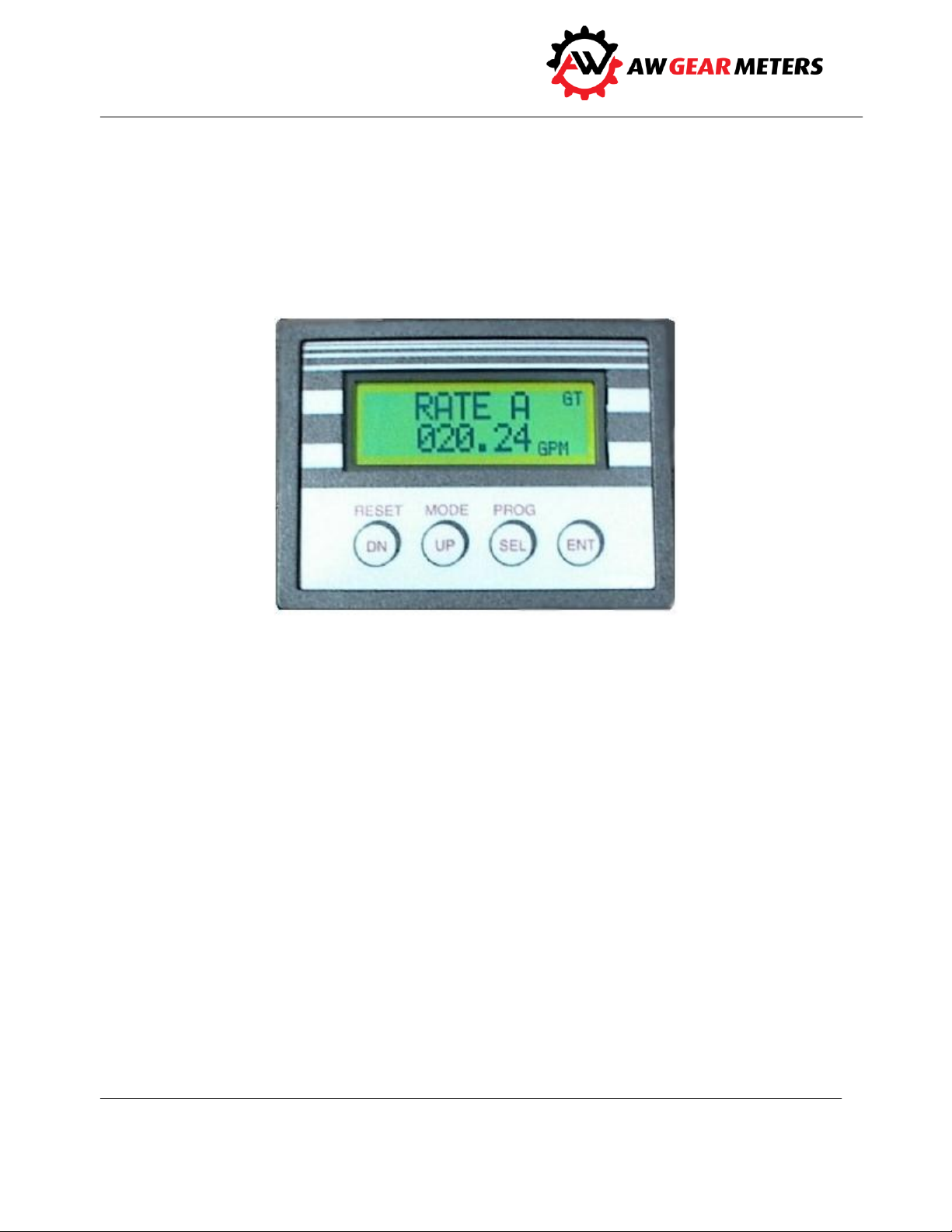
The FEM-03 Flow Monitor is a versatile, multi-functional device that helps you track rate, flow, limit,
ratio, and other variables. The unit’s large, back-lighted LCD display is easy-to-read with up to 22
different display modes available, depending on model. The standard unit is one channel, but the
optional two-channel version allows you to monitor dual flows and display them in a number of ways:
separately, as a sum (for example in total material use), as a difference (as in fuel consumption), or as a
ratio of product A/product B. You can also use the FEM-03 to detect bi-directional flow when A and B
channel signals are available from a single flow meter.
Other capabilities include the capacity to monitor data and program the unit remotely. Four model
variations give the FEM-03 the capability of performing limit, warning and alarm duties.
Principle of Operation
After first making connections to the power source and to flow transmitter input and output, you can
choose up to 22 display modes. These include rates, totals, ratios, limits, printer status, and others,
based on the model purchased. Then input k- and t-factor values, the required engineering units,
sampling rates, gate times, limits, etc. You may also program other values such as warning/alarm limits
and ratios, depending on model.
7
Page 9

FEM-03 Flow Monitor
FEM-03 A __
Single Channel Rate/Totalizer
Two Form C Limit Relay Outputs
RS232 Communications
Plus 4-20 MilliAmp Output
Dual Channel Rate/Totalizer
Bi-Directional Flow Indication = 2
Plus Ratio Monitor Option = X
Operation and Programming Manual
Features
RS-232 communication
Serial port for serial protocol communication or printer (adaptor required)
Two programmable Form C Relay outputs
Assignable 4-20 mA output (optional)
Large, easy-to-read LCD display
Single or dual channel models
Ratio monitor version available
Model Number Key
Technical Data
Power Supply
16 VAC/500mA. with supplied 110 VAC transformer, or
24 VDC/250mA. (customer supplied direct current)
Flow Sensor Power Supplies
(2) @ 15 VDC/20 mA. each
Frequency Inputs
0-4 KHz, sine, square or saw-tooth; 4 volts minimum amplitude; 10 KOhm impedance
8
Page 10
FEM-03 Flow Monitor
Maximum
Switched
Power
Resistive Load
DC: 60W
AC: 125VA
Inductive Load
DC: 30W
AC: 60VA
Maximum Switched Voltage
220V DC, 250V AC
Maximum Switched Current
2A
Rated
Load
Resistive Load
DC: 30V, 2A
AC: 110V, 0.5A
Inductive Load
DC: 30V, 1A
AC: 110V, 0.3A
Caution
Operation and Programming Manual
Analog Output 4-20 mA
self-powered loop output into a maximum 400 Ohm load impedance
Relay Contact Ratings
Do not use 115 VAC through relay contacts. Use 24 VDC instead.
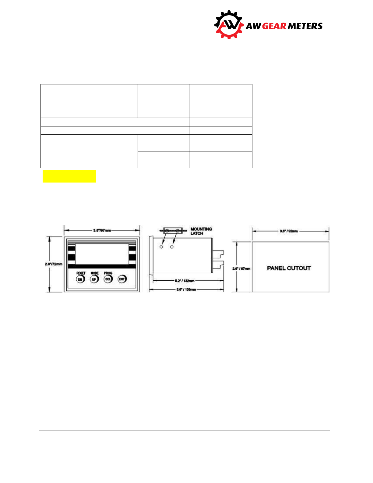
Dimensions
Input and Output Wiring Connections
Make all connections to the FEM-03 from the back of the unit. A plug-in connector from the wall plugtype power supply, normally supplied with the unit, delivers power. If necessary, any standard AC wall
plug unit providing 13-17VAC/250mA. or 18-24VDC/250mA. may be used. A standard female plug
(2.1mm I.D. x 5.5mm O.D.) supplies AC or DC power to the FEM-03. This connector is polarity insensitive.
The factory recommends tying one of the DC COMMON terminals to earth ground, especially for DC
operation.
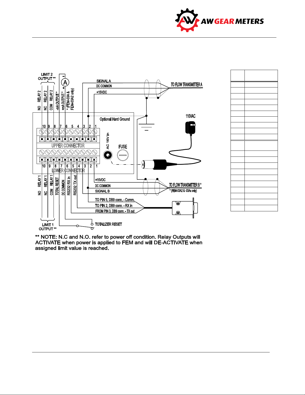
Make all other connections through the two rear terminal connectors. Called the “upper” and “lower”
connectors, they are removable and have ten connections each. A label on each connector shows
connection information. Refer to the Connection Diagram on page 12 for details and typical
9
Page 11

FEM-03 Flow Monitor
*
Operation and Programming Manual
connections. Refer to drawing #301199 FEM-03 on page 41 for schematic details of the FEM-03 inputs
and outputs.
Upper Connector Terminal Designations
UP 1 +15VDC OUT – power supply for the transmitter. Approx. 15VDC (power supply dependent),
approx. 20mA. max.
UP 2 DC COMMON – power supply common for the transmitter (floating).
UP 3 FREQ. A INPUT – frequency input from the transmitter. 0-4KHz, 4 volts minimum, 10Kohm
maximum input impedance. Used as primary frequency input, or for A channel of A and B pick-up sensor
(B = 90° phase shifted signal) to detect flow direction.
UP 4 NOT USED
UP 5 NOT USED
UP 6 (+) mA OUTPUT (models FEM-03A, -03A2 and -03Ax only). Positive assignable 0-20 mAmp
output. The low range of the output span is adjustable between 0 and 10mA. See ANALOG OUT on page
18 for information regarding the display of the mA output. When in Directional flow mode, (Model FEM03A2 only), the full signal span represents full positive-to-negative flow, with mid-span representing
zero flow. See ANALOG OUT Programming on page 27 for more information regarding analog output
setup.
UP 7 (-) mA OUTPUT (models FEM-03A -03A2 and -03Ax only). Negative assignable 0-20 mAmp
output. See (+) mA OUTPUT above.
UP 8 LIMIT 2 COMMON – common contact of Limit 2 Relay (Form C). See NOTE below. See the FEM-
03 Connection Diagram on page 12 for limit connection details. See Relay Contact Ratings Table on page
9 for contact ratings.
UP 9 LIMIT 2 N.C. – normally closed contact for Limit Relay 2 without power applied to FEM-03.
NOTE: The N.C. contacts become N.O.* whenever the FEM-03 has power applied with limit status OFF
and will CLOSE when limit status is ON. See LIMITS Display Mode on Page 18 and LIMITS Programming
on page 28 for information regarding limit display and programming.
UP 10 LIMIT 2 N.O. – normally open contact for Limit Relay 2 without power applied to FEM-03.
NOTE: The N.O. contacts become N.C. whenever the FEM-03 has power applied with limit status OFF
and will OPEN when limit status is ON. See LIMITS Display Mode on page 18 and LIMITS Programming
on page 28 for information regarding limit display and programming.
N.C. and N.O. = normally closed and normally open
10
Page 12

FEM-03 Flow Monitor
Operation and Programming Manual
Lower Connector Terminal Designations
DN 1 +15VDC OUT – power supply for the transmitter. Approx. 15VDC (power supply dependent),
approx. 20mA. max.
DN 2 DC COMMON – power supply common for the transmitter and serial port.
DN 3 FREQ. B INPUT – (model FEM-03A2 or -03Ax only). Frequency input from a transmitter. 0-4KHz,
4 volts minimum, 10KOhm maximum input impedance. Used as second frequency input, or for B
channel of A and B pickup sensor (B = 90° phase shifted signal) to detect flow direction.
DN 4 RS232 TX OUTPUT – transmit line of serial communication port. Connect to Pin 2 (RX in) on
DB9 serial port connector of PC. See Serial Communications on page 34 or PRINT Functions/Operations
on page 31 for more information regarding the use of the FEM-03 Serial Port.
DN 5 RS232 RX INPUT – receive line of serial communication port. Connect to Pin 3 (TX out) on DB9
serial port connector of PC. See Serial Communications on page 34 or PRINT Functions/Operations on
page 31 for more information regarding the use of the FEM-03 Serial Port.
DN 6 RESET TOTAL (labeled PREN) – momentary closure of RESET TOTAL terminal DN 6 with
terminal DN 7 DC COMMON resets the Job Total on closure and resumes totalizing upon opening the
connection.
DN 7 DC COMMON – common terminal used with RESET TOTAL terminal DN 6.
DN 8 LIMIT 1 COMMON – common contact of Limit 1 Relay (Form C). See NOTE below. See the FEM-
03 Connection Diagram on page 12 for limit connection details. See Relay Contact Ratings table on page
9 for contact ratings.
DN 9 LIMIT 1 N.C. – normally closed contact for Limit Relay 1 without power applied to FEM-03.
NOTE: The N.C. contacts become N.O. whenever the FEM has power applied with limit status OFF and
will CLOSE when limit status is ON. See LIMITS Display Mode on Page 18 and LIMITS Programming on
page 28 for information regarding limit display and programming.
DN 10 LIMIT 1 N.O. – normally open contact for Limit Relay 1 without power applied to the FEM-03.
NOTE: The N.O. contacts become N.C. whenever the FEM-03 has power applied with limit status OFF
and will OPEN when limit status is ON. See LIMITS Display Mode on Page 18 and LIMITS Programming
on page 28 for information regarding limit display and programming.
11
Page 13
FEM-03 Flow Monitor
#
UPPER
CONNECTOR
UP 1
+15 VDC Out
UP 2
DC Common
UP 3
Freq. A Input
UP 4
Not Used
UP 5
Not Used
UP 6
+ mAmp Output *
UP 7
- mAmp Output *
UP 8
Limit 2 Common
UP 9
Limit 2 N.C.
UP 10
Limit 2 N.O.
#
LOWER
CONNECTOR
DN 1
+15 VDC Out
DN 2
DC Common
DN 3
Freq. B Input **
DN 4
RS232 TX Out
DN 5
RS232 RX Input
DN 6
Reset Total
DN 7
DC Common
DN 8
Limit 1 Common
DN 9
Limit 1 N.C.
DN 10
Limit 1 N.O.
* FEM-03A and -03A2 only
**FEM-03A2 and -03Ax only
Operation and Programming Manual
12
Page 14

FEM-03 Flow Monitor
LOAD VARS FEM-03xx
TURN ON 0026.
MEM LEFT 099.9
VERSION 123 20xx
†
Operation and Programming Manual
Terms and Definitions
Following are basic terms and definitions you will need to know in order program and operate the FEM3 Flow Monitor.
Engineering unit a unit of measure, such as liter, cubic centimeter, gallon, ounce, gram, kilogram,
pound, rpm, or Hz.
K-factor (KFR) is a scaling factor based on the average number of transducer pulses per engineering
unit; used to determine rate
Gate time update time interval for display and analog output (.01 to 600 seconds) based on the
number counted during a prescribed time period
Rate Pulse update time interval for the display and analog output based on the time from pulse
edge to pulse edge
KFT scaling of total in engineering units
FEM-03 Start-Up Display Messages
The FEM-03 displays an initial window at power up. After 2 seconds, the FEM-03 displays the following
message for approximately 4 seconds:
LOAD VARS Indicates the device is recalling variables from EEPROM (electrically erasable
programmable read-only memory)
TURN ON Increments each time the FEM-03 powers up
MEM LEFT Displays percent of memory life remaining (.1% increments†)
VERSION Indicates the software version installed in the FEM-03
After this display, the FEM-03 reverts to the last active Display Mode.
The FEM-03 stores variables and totalizer values in EEPROM. Minimum EEPROM life is five years with continuous
use. Memory IC can be replaced on-site.
13
Page 15

FEM-03 Flow Monitor
Notice
Operation and Programming Manual
Be careful to insert the new memory IC in the exact orientation as the one you removed. You must re-
program user-defined variables after changing memory IC.
Display Modes
The FEM-03 displays following modes, depending on model and software:
LOGO RATIO A B**** RAT A RAT B**
RATE A GT RATIO B A**** TOT A TOT B**
RATE A PL ANALOG OUT* RATE A + B**
RATE B GT** LIMITS RATE A–B/TOTAL A–B***
RATE B PL** BATCH TOTAL SERIAL COM
TOTAL A RATE A DR** PRINTER SCR
TOTAL B** RAT A TOT A
STATUS ONE RAT B TOT B**
GT = Gate Time calculation method (see below) PL = Pulse Rate calculation method (see below)
*model FEM-03A, -03A2 or -03Ax only **model FEM-03A2 or -03Ax only
***TOTAL A-B Rev. 1.23 and after only ****model FEM-03Ax only
A typical display screen follows many of the descriptions below.
LOGO – FEM-03xx Screen
This screen displays the FEM-03xx model number. Enter the programming mode through this screen to
turn screens ON or OFF.
RATE
The FEM-03 continuously calculates rate by two methods simultaneously:
Pulse Width
Gate Time
The zero cut-off frequency for display and analog output is .3 Hertz.
14
Page 16

FEM-03 Flow Monitor
(FEM-03A2 and -03Ax only)
(FEM-03A2 and -03Ax only)
(FEM-03A2 and -03Ax only)
(FEM-03A2 and -03Ax only)
Operation and Programming Manual
Pulse Width Method
This method calculates rate based on the time from pulse edge to pulse edge. It updates more
frequently at high-input frequencies and less frequently with lower-input frequencies, producing stable
display response especially at frequencies below 100 Hz.
Gate Time Method
This method calculates rate based on the number of pulses counted during a prescribed time period.
The Gate Time Method updates at the same rate regardless of the input frequency, and produces the
most stable displays at frequencies above 100 Hz.
The initial mode (PL or GT) is always the default at power up. While in either RATE A or B GT or RATE A
or B PL display mode, use SEL to view or program the other method. Either or both methods can be
displayed as shown below:
RATE A or B GT (RATE A or B Gate Time)
The FEM-03 calculates the rate by the gate time method based on the programmed GATE AB variable; it
is displayed based on the corresponding KFR factors, decimal locations and engineering units. To show
RATE A or B PL, press SEL while in the RATE A or B GT display.
RATE A or B PL (RATE A or B Pulse Length)
The FEM-03 calculates the rate using the pulse length method and based on the SAMPLE A and SAMPLE
B variables; rate is based on KFR factors, decimal locations and engineering units. Press SEL to show
RATE A or B GT while in the RATE A or B PL display.
15
Page 17

FEM-03 Flow Monitor
(FEM-03A2 and -03Ax only)
(FEM-03A2 and -03Ax only)
Operation and Programming Manual
Job or Grand Total Channel A or B
The FEM-03 displays the JOB or GRAND total for channel A or B based on the KFTs, engineering units,
and decimal locations. The initial total display is JOB total, which shows the current total accumulating in
TOTAL A or TOTAL B. GR TOTAL is the actual real-time sum of JOB total plus the current value of the
GRAND total. View the Grand totals from the TOTAL display. Use SEL to switch between the TOTAL and
GR TOTAL. After a power cycle, the FEM-03 reverts to the JOB.
TOTAL A or B RESET
Use the RESET key DN to re-set job totals anytime while in TOTAL A or TOTAL B. Use the MODE key UP
to select any TOTAL A or B display. Press [RESET] DN to reset any job TOTAL to zero. Simultaneously
reset both JOB A and B totals while viewing the TOT A TOT B screen or at any time using the external
RESET TOTAL input. Momentary closure of terminal DN 6 RESET TOTAL with terminal DN 7 DC COMMON
resets all JOB totals on closure and resumes totalizing upon opening the connection. You can also reset
the JOB Totals using the serial port (see Variable Addressing and Serial Command Variables on page 37).
GR TOTAL A or B RESET
From the front panel, use a multiple-key entry sequence to reset Grand totals. Or reset via serial
command. Individual reset only.
To reset GR TOTAL A or B, use the MODE key UP to select TOTAL A or TOTAL B. With SEL, change to the
GR TOTAL display. Press the RESET and ENT keys simultaneously, and hold until the FEM-03 responds. A
warning appears on the screen requesting yes/no verification before you can reset the GR TOTAL. The
FEM-03 prompts you either to press the ENT key to accept the default answer of NO and exit the reset
procedure at this point, or to reset the total. To reset, use SEL first to toggle the response to YES, then
press ENT. This operation resets GR TOTAL to zero. See Variable Addressing and Serial Command
Variables on page 37 for serial reset of GRAND Totals.
TOTAL and GR TOTAL Rollover
FEM-03 JOB totals rollover to zero when the total reaches a value of 999999 regardless of the decimal
location. When a JOB total rolls over or is reset, the contents of the JOB total are then added in memory
to the GRAND total but not immediately to zero. To allow retention of the largest possible GRAND total
before data loss, after reaching a value of 999999, regardless of decimal location, a floating decimal
16
Page 18

FEM-03 Flow Monitor
Notice
Operation and Programming Manual
feature automatically reduces decimal resolution up to a maximum of two decimal places before rolling
over to zero and losing the total. Example: For a KFT with four decimal places, the GRAND total will
reach 9999.99 instead of 99.9999 before resetting to zero.
The FEM-03 retains both totals when the power is removed. These totals update every 25 seconds and
may not include previous flow for up to 25 seconds if flow was present when the power was removed.
STATUS ONE
The STATUS ONE screen shows:
RATE A
RATE B
the analog output value in mA
the analog input value (not implemented)
Rates are in Hz. and totals are in pulses. Use this screen to view the rates, totals, and output for setup or
troubleshooting.
PL
and TOTAL A
PL
and TOTAL B
RATIO AB/RATIO BA (FEM-03Ax only)
RATIO AB and RATIO BA indicate the direct ratio of flow A/B or flow B/A. If the ratio exceeds the ALARM
and/or WARNING limit, AL and/or WA appears on the left side of the screen. Program the parameters
for ratio monitoring, including ratio error WARNING and ALARM limit percentages, from the RATIO
screen. (See RATIO Programming on page 25.)
KFT A and KFT B Engineering Units must be the same. The RATIO display indicates NO MATCH if the A
and B KFT Engineering Units do not match. For WARNING or ALARM limits to function, you must assign
the LIMITS to the WARNING AB function. See LIMITS Programming on page 28 for information.
17
Page 19

FEM-03 Flow Monitor
Operation and Programming Manual
LIMITS
The FEM-03 has two programmable limit outputs: L1 and L2. The LIMIT display shows:
to what function each limit is assigned
the value (in engineering units) at which each limit becomes active
the current status of the limit outputs
The limit values are displayed using KFR or KFT, decimal location, and engineering units corresponding to
the limit assignment. See LIMITS Programming on page 28 for information regarding limit programming
and operation.
ANALOG OUT (FEM-03A, -03A2 and -03Ax only)
ANALOG OUT displays the analog output value in milliAmps. The two-digit number shown after ANALOG
OUT indicates which signal the output represents. For a listing of available output assignments and
corresponding numbers, see ANALOG OUT Programming on page 27.
BATCH TOTAL
BATCH TOTAL displays the JOB A TOTAL, and the S1 and S2 TOTAL LIMIT activation levels. When the
FEM-03 is programmed for BATCH TOTAL operation, both are assigned as TOTAL A limits based on the
KFT, decimal point, and engineering units. The TOTAL limit activation levels will display unless assigned
to another function. If so assigned, the S1 or S2 display reads XXXX to indicate that it is not assigned to
JOB A TOTAL function. See BATCH TOTAL Programming on page 30 for information regarding
programming.
RATE A DR (FEM-03A2 and -03Ax only)
RATE A DR displays the flow rate with a + or – sign to indicate direction. This display mode displays RATE
A PL based on the programmed KFR A, decimal point, and engineering units. RATE A DR requires a B
channel signal that is 90° phase shifted from the A channel signal to correctly determine flow direction.
18
Page 20

FEM-03 Flow Monitor
(FEM-03A2 and -03Ax only)
(FEM-03A2 and -03Ax only)
Operation and Programming Manual
RATE W/ TOTAL
Use the RATE A_TOT A or RATE B_TOT B displays to view RATE A or B PL and TOTAL A or B (Job or Grand).
RATE is based on the pulse length method. Rates and totals are shown in the engineering units based on
the programmed KFR and KFT factors and decimal locations. Use SEL to switch between GR TOTALs,
TOTAL A or B (TA or TB, and GR TOTAL A or B (GA or GB). After a power cycle, the FEM-03 reverts to the
Job Total (TA or TB).
RATE A and B/TOTAL A and B (FEM-03A2 and -03Ax only)
RATE A and B PL
Displays both RATE A and RATE B determined by the pulse length method and based on the
programmed SAMPLE A/SAMPLE B variables according to the corresponding KFR factors, decimal
locations and engineering units. Press SEL while in RATE A and B
power cycle, the FEM-03 reverts to RATE A and B PL.
PL
to display RATE A or B GT. After a
TOTAL A and B
Displays JOB or GRAND TOTAL A and TOTAL B based on the programmed KFTs, engineering units, and
decimal locations. The initial display is the JOB totals. Use SEL to switch between the JOB TOTAL A and B
(TA and TB), and GR TOTAL A and B (GA and GB). After a power cycle, the FEM-03 reverts to Job Total
(TA and TB).
19
Page 21

FEM-03 Flow Monitor
Notice
Operation and Programming Manual
RATE A + B/RATE A – B/TOT A – B (FEM-03A2 and -03Ax only, TOTAL A-B as of Rev 1.23
only)
For RATE A+B and RATE A-B, KFR A and KFR B Engineering Units must be the same. The display indicates
NO MATCH if the A and B KFR Engineering Units do not match. For TOTAL A-B and GRTOT A-B, both KFT
A and KFT B Engineering Units and number of decimal places must be the same. The display indicates NO
MATCH if the A and B KFT Engineering Units and number of decimal places do not match.
RATE A + B PL
Displays the sum RATE A and RATE B (PL or GT). Use SEL to toggle between RATE PL and RATE GT.
RATE A - B PL/TOT A - B
Displays the difference between RATE A and RATE B (PL or GT), TOT A and TOT B, or GRAND TOTAL A
and B. Use SEL to switch from RATE A_B PL to RATE A_B GT to TOTAL A_B to GRTOT A-B and back.
20
Page 22

FEM-03 Flow Monitor
Operation and Programming Manual
SERIAL PORT SETUP Display Mode
The SERIAL PORT SETUP display is useful during startup when the FEM-03 serial protocol (OPTOMUX) is
used for communication. Use this display to set the baud rate and unit number while in program mode,
or observe communications in display mode. To aid in startup and troubleshooting, the FEM-03 SERIAL
PORT SETUP screen displays any incoming strings in the RECEIVE line, and the FEM-03 response string in
the SEND line. When initiated, the FEM-03 SEND buffer contains the ASCII string “FEM.” To test
communications, the FEM-03 transmits the string shown in the SEND buffer plus a cr (carriage return)
each time you press the RESET DN key.
PRINTER SCR
The PRINTER SCReen displays the status of printer functions and the elapsed time since power was most
recently applied. The display indicates whether the PRINTER function is active and whether TIME PRINT
is operating. Whenever the display indicates active, the hardware print request input activates in
addition to any other print function. Although the display indicates active, the TIME PRINT function
defaults to a deactivated state whenever power to the FEM-03 is cycled. This prevents unexpected
printing activity. The operator must reactivate The TIME PRINT function after each power cycle. See
PRINT Functions/Operations on page 31 for complete information regarding FEM-03 printer functions.
Programming the FEM-03
Program all FEM-03 parameters from the corresponding display screen. For example, to program the A
Channel Rate scaling factor and engineering units, select RATE A PL or RATE A GT.
Most applications require programming of rate and total parameters, with additional parameters in
order to utilize limit outputs, serial communications, or the analog output (when applicable). In order to
program variables, the appropriate display mode must be active and on screen.
Basic Key Strokes
Using the UP key, first select the display mode for the area which you wish to edit or program. Press and
hold the ENT key. The display first shows a P in the lower left-hand corner and then displays the first
program variable for that mode. All parameters related to that display mode appear in order until you
21
Page 23

FEM-03 Flow Monitor
Notice
Operation and Programming Manual
have completed them. A blinking cursor highlights the active digit or field when entering or editing a
value. As you press SEL, the cursor starts on the left-most digit or character, moves to the right, and
wraps around to the left. Press and hold the UP or DN key to increase or decrease the value. When the
complete, desired value displays, press ENT to store it and advance to the next variable. The FEM-03
advances to the next variable for that mode until all are complete, and then resumes the display mode.
KFR A or B VALUE
The KFR is a scaling factor used in determining rate in a desired engineering unit such as GPM. The KFR
factor also determines the decimal resolution of the rate display. The FEM-03 calculates KFR using the Kfactor of the transducer being monitored. The K-factor is the number of impulses per engineering unit
established by the transducer manufacturer or by a calibration test.
The KFR is on the calibration data sheet supplied with the flow meter. You can also calculate the KFR
using the formula below:
Default is 100.00 (Hertz to two decimal places.)
To calculate the KFR factor, use the following formula: KFR= TIME BASE/K-FACTOR
Where:
- 100 is the TIME BASE constant for engineering units per second
- 6000 is the TIME BASE constant for engineering units per minute
- 360000 is the TIME BASE constant for engineering units per hour
- K-FACTOR is the average number of pulses per desired engineering unit that the
transducer produces.
1. Determine the number of decimal places desired for rate display.
2. Round off the result of the formula to the desired accuracy.
3. Enter the KFR using only that number of decimal places.
Using too few decimal places can cause relatively large display errors, up to several percent of actual
reading. Using too many decimal places can result in displays with a level of precision exceeding the
accuracy of the meter. The factory recommends using no more than four digits regardless of decimal
point position. The largest acceptable value for KFR is 65535 with the decimal in any location
(continued).
22
Page 24

FEM-03 Flow Monitor
Operation and Programming Manual
For example:
A flowmeter has a K-factor 2053.57 imp/Gal and the display should read in Gal/Min. with accuracy to
three decimal places.
KFR = 6000/2053.57 = 2.921741 for GPM
Round off 2.921741 to three decimal places and enter 2.922 for KFR.
GATE A B (Gate Time)
This variable
sets the sample time on the incoming frequency for the RATE A GT and RATE B GT (Gate Time)
displays
is programmed in tenths of a second (the allowable range is from .01 to 600 seconds)
affects the update of the display and analog output (FEM-03A, -03A2, or -03Ax only)
is useful in stabilizing the display and output when dealing with slight variations in flow
default is 002.00 seconds
When entering or editing the value, the digit being edited blinks starting with the left-most digit. Select
the digit to edit using SEL. Press and hold the UP or DN key to increase or decrease the value. When the
desired value displays, press the ENT key to store and advance to the next variable.
SAMPLE A or SAMPLE B
This variable
determines the amount of digital filtering performed on the incoming frequency for the RATE A
PL or RATE B PL (Pulse Length) display
affects the update of the display and analog output (FEM-03A, -03A2, or -03Ax only) and can be
used as a filter to stabilize the display and output
Flowable range is from 0 to 253 with 0 providing the least level of filtering and 253 the maximum;
default is 010.
When entering or editing the value, the digit blinks starting with the left-most digit. Select the digit to
edit using SEL. Press and hold the UP or DN key to increase or decrease the value. When the desired
value displays, press ENT to store and advance to the next variable.
23
Page 25

FEM-03 Flow Monitor
Notice
Operation and Programming Manual
ENG UNITS A or B
The desired engineering units for display of rate are programmable using up to four letters. Example:
GPM_
Default is: HZ__
The left-most character is highlighted with the blinking cursor first. The SEL key moves the cursor; use
the UP and DN keys to scroll through the alphabet. After you have entered all characters, press the ENT
key to store the variable.
Total Mode Programming
Program the Total parameters from the TOTAL A or TOTAL B display screen. Use the MODE key UP to
select the TOTAL A or TOTAL B display. Press and hold the ENT key until KFT appears.
TOTAL A or B
KFT A or B VALUE
ENG UNITS A or B
When entering or editing the value, the digit blinks starting with the left-most digit. Select the digit to
edit using the SEL key. Press and hold the UP or DN key to increase or decrease the value. When the
desired value displays, press ENT to store and advance to the next variable.
KFT A or B VALUE
The KFT is a scaling factor to display totals in a engineering unit such as Gallons. The KFT value also
determines the decimal resolution of the total display. The KFT is calculated using the K-factor of the
transducer being monitored. The K-factor is the number of impulses per engineering unit established by
the transducer manufacturer or by a calibration test.
You can obtain the KFR from the calibration data sheet supplied with the flow meter. You can also
calculate the KFR using the formula below:
Default is: 10000. (total pulses with no decimals)
To calculate the KFT factor, use the following formula:
KFT= 10000/K-FACTOR
Where:
10000 is a constant
24
Page 26

FEM-03 Flow Monitor
Notice
Operation and Programming Manual
K-FACTOR is the average number of pulses per desired engineering unit that the transducer
produces.
Method:
1. Determine the number of decimal places desired for total display.
2. Round off the result of the formula to the desired accuracy.
3. Enter the KFT using only that number of decimal places.
Using too few decimal places can cause relatively large display errors up to several percent of actual
reading. Using too many decimal places can result in displays with a level of precision exceeding the
accuracy of the meter. The factory recommends using no more than four digits regardless of decimal
point position. The largest acceptable value for KFT is 65535 with the decimal in any location.
For example: A flowmeter has a K-factor 2053.57 imp/Gal and the display should read in Gallons with
accuracy to three decimal places.
KFT = 10000/2053.7 = 4.869568 for Gallons
Round off 4.869568 to three decimal places and enter 4.870 for KFT.
ENG UNITS A or B
You can program the engineering units for display of total using up to four letters. Example: GALS.
Default is: PULS
The blinking cursor highlights the left-most character first. The SEL key moves the cursor. Use the UP or
DN keys to scroll through the alphabet. After you have entered all characters, press ENT to store the
variable. The FEM-03 exits the variable programming mode and returns to the Total display.
RATIO AB/RATIO BA Programming (FEM-03Ax only)
The RATIO AB or RATIO BA screens (FEM-03Ax only) set up the FEM-03 for use as a ratio monitor.
For RATIO operation, both KFT A and KFT B Engineering Units must be the same; the FEM-03 does not
allow programming of ratio functions if the A and B KFT Engineering Units do not match.
When programming, follow these guidelines:
Program the channel A and B KFTs, decimal locations, and engineering units from the TOTAL A
and TOTAL B displays.
Program the parameters for ratio monitoring, including the ratio error limit percentages, from
the RATIO screen.
25
Page 27

FEM-03 Flow Monitor
Notice
Notice
Operation and Programming Manual
For ratio warning and alarm limits, assign LIMITS to the RATIO function (see LIMITS
Programming on page 28)
To program RATIO, use the MODE key UP to select either the RATIO A/B or RATIO B/A display. Press and
hold the ENT key. The display first shows a P in the lower left-hand corner and then displays the first
program variable for this mode. Four parameters are accessed in order as follows:
RATIO A/B RATIO B/A
IDEAL AB IDEAL BA
WARNING AB WARNING BA
ALARM AB ALARM BA
TARGET NBR TARGET NBR
IDEAL AB/IDEAL BA
Use these individual variables to set the ideal ratio you wish to achieve for either A/B or B/A ratios. The
allowable range for either ratio is from .001 to 65.534 (the factory recommends programming no
smaller than a 0.010 ratio). The initial value of both IDEAL Ratios is 1.000.
WARNING AB/WARNING BA
The FEM-03 uses these individual variables to set the percent ratio error at which the L1 WARNING limit
activates. The ratio error limits are 1% to 100%. The initial value for either WARNING limit is 5.0 %.
For the RATIO WARNING limit to function, you must assign the L1 LIMIT to the WARNING function. See
LIMITS Programming on page 2812.
ALARM AB/ALARM BA
The FEM-03 uses these individual variables to set the percent ratio error at which the L2 ALARM limit
activates. The ratio error limits are 1% to 100%. The initial value for either ALARM limit is 10.0 %.
For the ratio alarm limit to function, you must assign the L2 LIMIT to the ALARM function. See LIMITS
Programming on page 28.
TARGET NBR
The FEM-03 uses this variable to set the number of pulses it samples before making and programming a
ratio. The FEM-03 uses the TARGET NUMBER for both the RATIO A/B and RATIO B/A calculation. The
device performs a calculation whenever either channel accumulates the TARGET NUMBER since it
calculated the previous ratio. If the TARGET NBR is too small, the ratio calculation can consistently
26
Page 28

FEM-03 Flow Monitor
Operation and Programming Manual
produce large errors. If the TARGET NBR is too large, the ratio will not be calculated frequently. The
allowable range for TARGET NBR is from 1 to 65534. The recommended typical range for values is from
200 to 2000. Initial value is 500.
ANALOG OUT Programming (FEM-03A, -03A2 and -03Ax only)
The FEM-03A, -03A2 and -03Ax have a 12-bit analog output with programmable span and scaling. The
output span can be configured between 0 to 20mA and 10 to 20mA using the MA OFFSET parameter.
The flow rate or total represented by the maximum output is programmable. When the output is
assigned to FLOW A DR, the mid-point of the output span represents zero flow, with maximum positive
or negative flow producing the maximum or minimum output. For example, with the MA OFFSET
programmed for 4 mA, the output ranges from 4 mA for maximum negative flow to 12 MA for zero flow,
to 20 mA for maximum positive flow. This result can be processed as positive and negative by using
offset compensation that can be accomplished with most data recording devices.
From the ANALOG OUT screen, program the signal assignment, offset, and scaling values for the mA
output. Use the MODE key UP to select the ANALOG OUT display. Press and hold the ENT key. The
display first shows a P in the lower left-hand corner and then displays the first program variable for this
mode. The FEM-03 accesses these parameters in order:
MA OFFSET
ANALOG POINT
ENTER VALUE AT MAX Mas
MA OFFSET
The FEM-03 uses this variable to set the lowest value for the mA output span and as a fine offset
adjustment in the field, if necessary. The low range of the output span is between 0 and 10 mA. The
initial value is set to produce 4.00mA at the output for a zero value of the assigned variable.
ANALOG POINT
The FEM-03 uses this variable to “point” to an output assignment for the analog output. The output can
be assigned to represent one of eight possible functions depending on the FEM-03A model:
RATE A GT (#00) TOTAL A (#04)
RATE A PL (#01) TOTAL B (#05)*
RATE B GT (#02)* A B DIFF (#06)** (Rate A-B)
RATE B PL (#03)* RATE A DIR (#07)*
*FEM-03A2 or –03Ax only. **FEM-03A2 or –03Ax Rev. 122 and after only
27
Page 29

FEM-03 Flow Monitor
Caution
Operation and Programming Manual
The number displayed indicates the current function of the analog output. The initial assignment for the
ANALOG POINT is RATE A GT (#00). RATE or TOTAL produces an output ranging from the MA OFFSET
value (0-10 mA) for a zero value, to 20 mA for the maximum programmed flow rate or total.
RATE A DIR is only for bi-directional flow-rate and will split the output span in half producing an output
between 10 and 15mA (depending on MA OFFSET) for zero flow. The output increases up to 20mA for
positive flow, and decreases to the MA OFFSET value (0-10 mA) for negative flow based on the
programmed VALUE AT MAX MA’S.
ENTER VALUE AT MAX MA’S
FEM-03 uses this scaling variable to set the maximum mA output (20mA.) to a corresponding rate or
total value, which the user has selected above with ANALOG POINT. If RATE A DIR is selected, this VALUE
represents the flow rate at the maximum and minimum of the mA output span with the mid-span
indicating zero flow. The entries correspond to the KFT or KFR, decimal location, and engineering units
for the source selected with ANALOG POINT. The initial value is 10 HZ.
LIMITS Programming
Program Limits from the LIMIT screen. Assign L1 and L2 to any of the following functions (note
exceptions). Initial assignment is TOTAL A for L1 and L2.
RATE A GT RATE B PL* CYCLE OUT
RATE A PL TOTAL A WARNING/ALARM AB**
RATE B GT* TOTAL B* WARNING/ALARM BA**
*Model FEM–03A2 only. **Model FEM–03Ax only.
Do not assign to these functions unless the FEM-03 model supports the feature, or the limit will not
function properly.
RATE Limits/Limit MARGIN
To operate a limit based on RATE, select a RATE A or RATE B function based on pulse length or gate time
measurement. The MARGIN variable is programmed in engineering units and determines whether the
limit functions as an absolute limit or activates within a margin or “window” around the programmed
RATE limit. When the user programs the MARGIN as zero, the limit activates whenever the selected
RATE equals or exceeds the programmed value. When the user enters a MARGIN value other than zero,
the limit is active whenever the selected RATE is within the “window” of the programmed RATE limit
value plus or minus the MARGIN value.
28
Page 30

FEM-03 Flow Monitor
Operation and Programming Manual
TOTAL Limits
To operate a limit based on the JOB TOTAL, select TOTAL A or TOTAL B for the Limit function. The limit
activates whenever the TOTAL equals or exceeds the programmed value.
CYCLE OUT
Assigning a limit to the CYCLE OUT function toggles the state of the limit output whenever Job TOTAL A
increments by the cycle amount. The output remains ON until the cycle amount accumulates, and turns
OFF until the cycle amount accumulates again. The total accumulated between a rising and falling edge
is the cycle value. The total accumulated between any two rising or any two falling edges is twice the
cycle value. The cycle value in engineering units corresponds to the KFT and decimal location. It is highly
recommended that you do not program a cycle amount that produces more than one pulse per second.
Consider the average flowrate to determine an acceptable resulting output frequency. When
considering a large cycle amount, keep in mind that any external totalizer will miss up to one cycle
amount of accumulation whenever power cycles to the FEM-03. Assign either or both limits to CYCLE
OUT.
WARNING/ALARM Limits (FEM-03Ax only)
Used for ratio monitoring applications, the WARNING/ALARM AB and WARNING/ALARM BA
assignments operate with the RATIO AB or RATIO BA program variables. Assigning WARNING AB or
WARNING BA causes the limits to function as ratio limit outputs which will activate whenever the ratio
of A/B or B/A differs from the programmed ideal ratio by an amount equal to or greater than the
assigned % error value. Program the IDEAL RATIO and the ratio WARNING% and ALARM% from the
RATIO AB or RATIO BA display screen. When assigned to WARNING/ALARM functions, L1 assumes the
value from the WARNING%, and L2 assumes the value from the programmed ALARM% variable. The
limits are in percent, from 1 to 100%. The initial WARNING and ALARM error limit values are 5% and
10% respectively. Program the % value for ratio WARNING/ALARM assignments from either the LIMITS
or RATIO programming screens.
Programming the Limit Functions
To program the limit functions, use the MODE key UP to select the LIMIT display.
1. Press and hold the ENT key. The display first shows a P in the lower left-hand corner and then
highlights the L1 indication with a blinking cursor.
2. Use the SEL key to select the function of the limit assignment.
3. Press ENT when the desired mode is displayed; the cursor highlights the numeric value for L1.
Entries correspond with the scaling factor, decimal location and engineering units for the
function selected. The left-most digit is highlighted with a blinking cursor.
4. Move the cursor left to right using the SEL key. Use the UP or DN to increase or decrease each
digit’s value.
5. When you have completed editing and the desired value displays, press ENT to store the value
for L1. If a RATE assignment has been made, the FEM prompts the user to enter the RATE LIMIT
29
Page 31

FEM-03 Flow Monitor
Notice
Operation and Programming Manual
MARGIN in percent. The left-most digit is highlighted with the blinking cursor. Move the cursor
using the SEL key. Use the UP or DN key to increase or decrease each digit’s value.
6. When editing is complete and the desired value is displayed, press ENT to store the
programmed RATE LIMIT MARGIN. The FEM highlights the L2 indication with a blinking cursor.
7. Repeat the procedures used for L1.
8. When the L2 programming is complete, press ENT to store the programmed values and exit
LIMITS programming.
See the Input and Output Wiring Connections beginning on page 9 and the Connection Diagram on page
12 for important information regarding NORMAL state of limit output relays.
BATCH TOTAL Programming
Use the BATCH TOTAL program mode to quickly dedicate both limits as total limits and program the
values at which the limits (labeled S1 and S2) activate.
1. Using the MODE key UP, select the BATCH TOTAL display. Press and hold the ENT key. The
display shows a P in the lower left-hand corner and then highlights the first limit assignment S1
with a blinking cursor.
2. Enter a value to assign the limit as a total limit based on the KFT, decimal location and KFT
engineering units. Select the digit to edit using the SEL key.
3. Use UP or DN to increase or decrease the value.
4. When the desired value displays, press ENT to store and move the cursor to S2.
5. Select the digit to edit using the SEL key. Use UP or DN to increase or decrease the value.
6. When the desired value is displayed, press the ENT key to store and exit the BATCH TOTAL
program mode.
If either limit has been previously assigned to a function other than TOTAL A, the FEM will respond by
asking “Limit mode different, want to change it?” Use the SEL key to toggle a “N” or “Y” response and
use the ENT key to answer. A “Y” response resets any previous limit assignment to Total A and zeros the
limit value. A “N” response leaves the limit assigned to the previous function and the S1 or S2 display
will read XXXX to indicate that it has no function in this mode.
SERIAL PORT SETUP Programming
Use the SERIAL PORT SETUP display to program the port parameters for protocol communication or
printer operation.
To program, follow this procedure:
30
Page 32

FEM-03 Flow Monitor
Notice
Notice
Operation and Programming Manual
1. Press and hold the ENT key to access the parameters for the serial port. A “P” appears in the
lower left hand corner and SELECT SPEED appears in the second line of the display.
2. Use the SEL key to select from the four available choices:
9600 (default) 19200 38400 57600
3. When the desired baud is displayed, press ENT to store. UNIT NUMBER appears next in the
second line with the blinking cursor highlighting the left-most digit. The initial value is 001.
4. Select the digit to edit using the SEL key. Use UP or DN to increase or decrease the value.
5. When the desired value displays, press ENT to store and exit the SERIAL PORT SETUP program
mode.
The FEM can have a unit number from 1 to 200 although only one unit can be addressed at a time on the
serial line with RS232 communication. If RS422 or RS485 communications are accomplished using
converters, up to 200 units can be addressed and accessed individually using the OPTO22 Company
OPTOMUX serial protocol.
FEM-03 Printer Functions/Operation
The FEM-03 supports some basic print functions when connected to a standard parallel printer using a
serial-to-parallel converter. The FEM-03 generates a printout of the current elapsed time since poweron, a sequential printout number, Rate A PL, Rate B PL, Job TOTAL A, and Job TOTAL B. You can initiate
these on a timed basis or single printouts via the touch-keys or a hardware input. In addition, the FEM03 can generate a printout of all the programmed values.
The PRINTER SCReen displays the status of the FEM-03 printer functions (see PRINTER SCReen on page
21) and is used to activate and deactivate printer functions. Once you activate any PRINTER function, the
hardware print request input also activates and remains active (even when power is reapplied to the
FEM-03) until the PRINTER is deactivated through the programming screen. The display indicates
PRINTER ACTIVE after a power cycle to show that the hardware print request input is still active.
However, TIME PRINT operation halts whenever power to the FEM is removed; and it must be
reactivated after each power cycle.
While any PRINTER Function is activated, the OPTO-22 protocol for the serial port is disabled.
Printer Modes
There are four PRINTER operating modes:
31
Page 33

FEM-03 Flow Monitor
Operation and Programming Manual
TIME PRINT
The FEM-03 prints the following:
the current elapsed time since power-on
a sequential printout number
Rate A
Rate B
Job TOTAL A
Job TOTAL B
These print at a specified time interval in Hours. Valid numbers are 00.001 Hours (3.6 seconds) to 10.000
Hours. TIME PRINT reverts to a disabled state whenever power to the FEM is removed, and must be
reactivated after each power cycle.
DO NOTHING (hardware print request)
In this mode, the FEM-03 will “do nothing” until the hardware input is recognized. The FEM-03 RS232
Receive input is used to request a printout. When this mode activates, each momentary connection of
the FEM-03 RS232 RX input (terminal DN 5) to 15VDC (terminal DN 1) causes the FEM-03 to print:
PL
PL
the current elapsed time since power-on
a sequential printout number
Rate A
Rate B
PL
PL
Job TOTAL A
Job TOTAL B
Once this or any PRINTER function is active, the hardware print request input is also active and remains
active (even when power is reapplied to the FEM-03) until the user deactivates the PRINTER from the
programming screen.
SYSTEM INFO PRINT
Initiates a printout of all the programmed values contained in the FEM-03, providing up to 46 pieces of
information, depending on model.
SINGLE PRINT
This mode initiates a single printout of:
the current elapsed time since power-on
a sequential printout number
Rate A
Rate B
PL
PL
Job TOTAL A
32
Page 34

FEM-03 Flow Monitor
Operation and Programming Manual
Job TOTAL B
Activate Mode of Choice
To activate and select a printer function:
1. Select the PRINTER SCR display using the UP key.
2. Press and hold ENT until the FEM-03 displays the “PRINTER ON” prompt.
3. The unit first offers a NO response. To activate a print function, use the SEL key to toggle the
response to YES and press ENT. The unit now prompts for the mode selection.
4. Use the SEL key to select the print operation, and press ENT to initiate the print operation.
PRINTER Hardware Specification/Connection
The factory has tested printer operation with the following combination of equipment:
FEM-03 all models (any software version after/including rev. 1.06)
SXP-320A RS232 serial to parallel converter (JAMECO Catalog Part Number 116935)
HP Deskjet 672 C
The SXP-320A parallel connector plugs directly into the printer, and the serial connector is a 25-pin
female D-sub. Connections between FEM-03 and SXP-320A are as follows:
FEM-03 TX output ( terminal DN 4) connects to pin 2 (RX input) on the 25 pin D-sub.
FEM-03 Common ( terminal DN 6) connects to pin 7 (comm./gnd) on the 25 pin D-sub.
The SPX-320A must be configured as follows:
Baud rate = 9600 (or 19200, 38400, or 57600) Must match the FEM-03 baud rate!
Handshake = XON/XOFF
Data Length = 8 Bits (1 stop bit automatically)
Parity = None
Data direction = S P (serial to parallel)
Configure the FEM-03 baud rate as follows:
1. Use the UP key to select the SERIAL COM display.
2. Press and hold ENT to access the parameters and verify or select a baud rate matching
the SXP-320A converter (9600 recommended). Must match the SXP-320A baud rate!
33
Page 35

FEM-03 Flow Monitor
Notice
Operation and Programming Manual
FEM-03 Serial Communications
The FEM-03 has RS-232 serial port connections on the Lower Connector on the back panel. The user can
connect this port to a host computer, and then Read or Write to any RAM memory location in the FEM03 using the OPTOMUX serial protocol. The RS-232 terminals on the Lower connector are:
terminal DN 2 = DC Common - connect to pin 5 ( comm.) of DB9 serial connector
terminal DN 4 = TX transmit - connect to pin 2 ( RX in) of DB9 serial connector
terminal DN 5 = RX receive - connect to pin 3 ( TX out) of DB9 serial connector
Serial Protocol Format
The FEM-03 uses a protocol format that follows OPTOMUX by the OPTO 22 Company, in which all the
string data is transmitted and received in Hexadecimal notation. All data is received and transmitted
without engineering units as Hertz or pulses. The KFR or KFT and corresponding decimal point location
data is always needed to convert the responses to decimal numbers in engineering units with the
correct decimal resolution. NOTE: While any PRINT Function is activated, the OPTO-22 protocol for the
serial port is disabled.
^ means “add one letter or digit”; ^^ means add two letters or digits, ^^^ means add three letters or
digits, etc.; “cr” means “carriage return.”
The format for reading from the FEM-03 is as follows:
>01K0F3404XXcr
^...........………….start of string must use the > sign
^^..........………….unit number 1 to 200 (01H to C8H)
^..........………….. write/write command, K for read
^^^^......………….address to read from (in Hex)
^^....………….number of bytes to read (in Hex)
^^..…………..checksum for the string 01K0F3404 (in Hex, LSB of checksum)
..………….carriage return ends the string
34
Page 36

FEM-03 Flow Monitor
Operation and Programming Manual
The answer received back from the FEM-03 will look like this:
A03E36712XXcr
^.............……….all answers start with A
^^...........……….low byte in Hex at address 0F34 (MSB)
^^.........……….next byte in Hex at address 0F35
^^....………....next byte in Hex at address 0F36
^^.....………..high byte in Hex at address 0F37 (LSB)
^^...………...checksum
..………….carriage return ends the string
The protocol format for writing to the FEM-03 is as follows:
>01J03340F3587XXcr
^..................…………start of string must use the > sign
^^...............…………..unit number 1 to 200 (01H to C8H)
^..............…………....write/write command, J for write
^^^^..........……………address to write into
^^.....…………..…..byte written in Hex to 0334 (MSB)
^^....………….……byte written in Hex to 0335
^^...………….…….byte written in Hex to 0336 (LSB)
^^..………….……...checksum (in Hex, LSB of string checksum)
.………….….……carriage return
If the write was successful, the answer received back from the FEM-03 looks like this:
Acr.
^..................………Acknowledged write operation
...............…………..carriage return
35
Page 37

FEM-03 Flow Monitor
ASCII
Decimal
ASCII
Decimal
0
48 A 65 1 49 B 66
2
50 C 67 3 51 D 68 4 52 E 69
5
53 F 70 6 54 7 55 8 56 J 74 9 57 K 75
Warning!
Operation and Programming Manual
Serial Error Codes
If a read or write operation is not successful, the Fem-03 returns one of the following error messages:
NO1cr – Undefined command (something other than K/J)
NO2cr – allowable read range exceeded (addresses 0 to 500 [000H to 01F4H] allowed)
NO3cr – read error (read request exceeded 12 characters)
NO4cr – FEM detected a checksum error in the lower byte
NO5cr – FEM detected a checksum error in the higher byte
Checksum Calculation
The checksum calculation for the string variables in the Rate A PL read command would be as follows:
>01K000004XXcr
^^^^^^^^^^.......these characters are used in the calculation.
Add the values for the ASCII Decimal variables.
HEX 0 + 1 + K + 0 + 0 + 0 + 0 + 0 + 4
ASCII 48 + 49 + 75 + 48 + 48 + 48 + 48 + 48 + 52 = 464
To calculate the final checksum, convert the decimal number 464 into HEX (464=1D0 hex) and take the
last two characters (D0). The final string would look like this:
>01K000004D0cr
ASCII characters needed for checksum calculations are:
36
Page 38

FEM-03 Flow Monitor
Operation and Programming Manual
The FEM-03 does not discriminate any addresses. This means that any address can be written to as well
as read from. Writing to certain addresses can seriously alter the operation of the FEM-03. Use
extreme caution when attempting to write to the FEM-03 variable locations. Double check addresses
and variables before writing to the FEM-03!
Variable Addressing and Serial Command Variables
The FEM-03 stores all data it uses in two locations:
Run-Time RAM memory and
EEPROM Backup memory
The memory the device uses during regular operation is in the Run-Time location. All Run-Time variables
are in the RAM area of the microprocessor and are lost when power is removed from the FEM. All useraccessible data locations are RUN-TIME data addresses.
So that the FEM-03 can retain this information at power down, it stores a copy of each variable in the
backup memory whenever the user programs a variable on the keyboard. The FEM also stores the
totalizer values to EEPROM memory once every 25 seconds. The FEM-03 recalls these EEPROM variables
to RAM memory on power up. When editing a variable using serial protocol, the UPDATE EEPROM Serial
Command Variable must be used afterwards in order to save a copy of any altered variables in the
backup memory. If this is not done, the FEM loses the new value in RAM and recalls the previous value
from EEPROM on the next power up.
All data is in Hexadecimal form in raw Hertz. or pulses. The KFR and KFT along with decimal locations
must be used to manipulate the rate or total data into ASCII form with the programmed decimal places.
GRAND Total memory locations only update when the JOB Totals are reset or overflow. Therefore the
JOB Total memory location can contain zero until the JOB Total value transfers to the GRAND Total with
a Job Total reset or overflow. The actual total usage in at any given moment is the sum of the JOB and
GRAND Total memory locations.
The FEM-03 also uses some specialized Serial Command Variables including these commands:
Serial RESET
Update EEPROM
RELAY Override
FORCE mA Output
For serial reset of totals, DO NOT write over the Job or Grand Totals but instead use the specified
RESET TOTAL Serial Command Variable. In order to interrogate or write to the FEM-03, the RAM
memory locations of each variable must be known. Following are locations of the most significant
operating variables and FEM Serial Function Commands:
37
Page 39

FEM-03 Flow Monitor
Read/Write Variables
Address
Length
Data
Rate A (PL measurement)
0000H
4Bytes
MSB first
Rate A (GT measurement)
0037H
4Bytes
MSB first
Job Total A (READ ONLY)
0004H
4Bytes
MSB first
Grand Total A (READ ONLY)
0020H
4Bytes
MSB first
A-KFR for Rate
0071H
2Bytes
MSB first
A-KFR decimal point location
0075H
1Byte
A-KFT for Total
0073H
2Bytes
MSB first
A-KFT decimal point location
0076H
1Byte
A-Rate Engineering units
0085H
5Bytes
Array last digit 0
A-Total Engineering units
008FH
5Bytes
Array last digit 0
A-Flow Direction
00BEH
1Byte
Rate B (PL measurement)
000EH
4Bytes
MSB first
Rate B (GT measurement)
003BH
4Bytes
MSB first
Job Total B (READ ONLY)
0012H
4Bytes
MSB first
Grand Total B (READ ONLY)
0024H
4Bytes
MSB first
B-KFR for Rate
0077H
2Bytes
MSB first
B-KFR decimal point location
007BH
1Byte
B-Rate Engineering units
008AH
5Bytes
Array last digit 0
B-KFT for Total
0079H
2Bytes
MSB first
B-KFT decimal point location
007CH
1Byte
B-KFT for Total engineering units
0094H
5Bytes
Array last digit 0
Limit 1 Mode
00B3H
1Byte
1=Rate A Gate time
2=Rate A Pulse length
3=Rate B Gate time
4=Rate B Pulse length
5-Totalizer A
6=Totalizer B
Limit 1 (could be Rate or Total)
00B4H
4Bytes
MSB first
Margin 1 for rate limit
00DEH
4Bytes
MSB first
Limit 2 Mode
00B8H
1Byte
1=Rate A Gate time
2=Rate A Pulse length
3=Rate B Gate time
4=Rate B Pulse length
5-Totalizer A
6=Totalizer B
Limit 1 2 could be Rate or Total)
00B9H
4Bytes
MSB first
Margin 2 for rate limit
00E2H
4Bytes
MSB first
Milli-amps Offset
00AFH
4Bytes
MSB first
Milli-amps Out
002BH
4Bytes
MSB first
Analog Out Mode
002AH
1Byte
Operation and Programming Manual
38
Page 40

FEM-03 Flow Monitor
Read/Write Variables
Address
Length
Data (Cont’d)
Serial Speed
00C2H
1Byte
1=9600 Baud
2=19200 Baud
3=38400 Baud
4=57600 Baud
Unit Number (communication offset)
00BFH
1Byte
Default is 01
FEM Serial Command Variables
Address
Length
Data
Serial RESET TOTAL Command
00C4H
1Byte
will return to 0
1=Resets Job A
2= Resets Job B
3= Resets Jobs A and B
4=Resets Grand and Job A
5-Resets Grand and Job B
6=Resets All
Update EEPROM Command
00C5H
1Byte
will return to 0
Any number except 0
moves all Run time Variables to
the EEPROM location.
RELAY Override Command
00C6H
1Byte
write zero to release
80H Relay 1 and Relay 2 ON
81H Relay 1 OFF and Relay 2 ON
82H Relay 2 OFF and Relay 1 ON
83H Relay 1 and 2 OFF
Force mA Output Command
002DH
2Bytes
MSB first
(FEM-03 and -03A2 only)
Writing any number between 1
and 4095 (0001Hex and 0FFF Hex)
activates the mA output where: 1
= .005mA and 4095 = 20mA.
Writing a 0 returns the control to
the FEM-03.
Operation and Programming Manual
Example QBASIC Program for Protocol Communications
Below is a QBASIC program that allows the user to communicate with the FEM-03 by initiating serial
port #1 at 9600 baud and prompting the user for read or write strings. The program assembles strings
following the OPTO 22 protocol format described on page 34. All string data must be in Hex notation. Do
not enter the > sign before the string and do not calculate the checksum. The program calculates the
checksum, assembles the string, adds the cr, and sends the string to the FEM.
39
Page 41

FEM-03 Flow Monitor
Operation and Programming Manual
DEFINT A-Z
'* Serial Communication Test Program for OPTOMUX Code
'* For use with AW Company's FEM-03 Series Flow Computers
* Open serial port #1 to 9600 baud
OPEN "COM1:9600,N,8,1,RS,CS,DS,CD" FOR RANDOM AS #1
'* set up loop for transmitting several strings
CLS
DO
PRINT "Enter String to send. (Press ENTER alone to END)"
INPUT "Transmitting String: >", Transm$
IF LEN(Transm$) = 0 THEN END
'* Calculate Checksum
Chk = 0
FOR Char = 1 TO LEN(Transm$)
Chk = Chk + ASC(MID$(Transm$, Char, 1))
NEXT
Chk$ = HEX$(Chk)
'* Must be 2 characters, 1 byte
IF LEN(Chk$) < 2 THEN Chk$ = "0" + Chk$
'* Add the recognition character plus checksum
'* use only the last byte of checksum
Transm$ = ">" + Transm$ + RIGHT$(Chk$, 2)
'* Send it to the EMO
PRINT #1, ; Transm$; CHR$(13);
'* Read what the EMO sending back
LINE INPUT #1, Receive$
PRINT "Received: "; Receive$
PRINT
LOOP
40
Page 42

FEM-03 Flow Monitor
Operation and Programming Manual
41
Page 43

FEM-03 Flow Monitor
AW Gear Meters warrants the product to be in good working order for a period of 1 (one) year
from the date of purchase from AW Gear Meters or an authorized AW Gear Meters distributor.
Should the product fail to be good working order at any time during this 1-year warranty period,
AW Gear Meters will, at its option, repair or replace the product at no additional charge except as
set forth below. Repair parts and replacement products will be furnished on an exchange basis and
will be reconditioned or new. All replaced parts and products become the property of AW Gear
Meters. This limited warranty does not include service to repair damage to the product resulting
from accident, disaster, abuse, or a non AW Gear Meters modification to the product.
Limited Warranty service may be obtained by delivering the product during the 1-year warranty
period to AW Gear Meters and provide proof of purchase date. If this product is delivered by mail,
you agree to insure the product or assume the risk of loss or damage in transit, to prepay shipping
charges to warranty location and use the original shipping container or equivalent.
For further information contact:
ALL EXPRESS AND IMPLIED WARRANTIES FOR THIS PRODUCT INCLUDING THE WARRANTIES OF
MERCHANTABILITY AND FITNESS FOR A PARTICULAR PURPOSE, ARE LIMITED IN DURATION TO A
PERIOD OF 1 (ONE) YEAR FROM DATE OF PURCHASE, AND NO WARRANTIES, WHETHER EXPRESS
OR IMPLIED, WILL APPLY AFTER THIS PERIOD. SOME STATES DO NOT ALLOW LIMITATIONS ON
HOW LONG AN IMPLIED WARRANTY LASTS, SO THE ABOVE LIMITATIONS MAY NOT APPLY TO
YOU.
IF THIS PRODUCT IS NOT IN GOOD WORKING ORDER AS WARRANTED ABOVE, YOUR SOLE
REMEDY SHALL BE REPAIR OR REPLACEMENT AS PROVIDED ABOVE. IN NO EVENT WILL AW
COMPANY BE LIABLE TO YOU FOR ANY DAMAGES, INCLUDING ANY LOST PROFITS, LOST SAVINGS
OR INCIDENTAL OR CONSEQUENTIAL DAMAGE ARISING OUT OF THE USE OR INABILITY TO USE
SUCH PRODUCT, EVEN IF AW COMPANY HAS BEEN ADVISED OF THE POSSIBILITY OF SUCH
DAMAGES, OR FOR ANY CLAIM BY ANY OTHER PARTY.
THIS WARRANTY GIVES YOU SPECIFIC LEGAL RIGHTS, AND YOU MAY ALSO HAVE OTHER RIGHTS,
WHICH MAY VARY FROM STATE TO STATE.
AW Gear Meters
8809 Industrial Drive
Franksville, WI 53126
Phone: (262) 884-9800
Fax: (262) 884-9810
Operation and Programming Manual
Limited Warranty
42
Page 44

8809 Industrial Drive
Franksville, WI 53126
800-850-6110
©2012 AW-Lake Company All rights reserved. Doc ID: FEM03MAN
www.awgearmeters.com
 Loading...