

Page 1
EMO-500
TWO-COMPONENT RATIO MONITOR
OperaƟon & InstallaƟon Manual
Rev. 6
Page 2

EMO-500
Operation and Programming Manual
Table of Contents
Safety Definitions and Information ............................................................................................................... 4
Unpacking ..................................................................................................................................................... 4
Quick Start Guide .......................................................................................................................................... 5
Connect to Flow Transmitters ................................................................................................................... 5
Connect Unit to Power .............................................................................................................................. 7
Overview of Display Screens ..................................................................................................................... 8
Product Description ...................................................................................................................................... 9
Features .................................................................................................................................................... 9
Principle of Operation ............................................................................................................................... 9
Technical Data ........................................................................................................................................... 9
Key Programming Features ....................................................................................................................... 9
Technical Information ............................................................................................................................... 9
Display Information................................................................................................................................. 10
Special Features ...................................................................................................................................... 10
Helpful Information For Using the EMO-500 .......................................................................................... 10
Sample Size ......................................................................................................................................... 10
Gate Time ............................................................................................................................................ 10
Serial Port Programming ..................................................................................................................... 10
Hardware Connections ............................................................................................................................... 11
Grounding Considerations ...................................................................................................................... 11
Signal and Shielding ................................................................................................................................ 11
External Resets and Controls (Hardware) ............................................................................................... 12
External Resets and Controls (Definitions) ............................................................................................. 13
Reset All .............................................................................................................................................. 13
Scroll Display ....................................................................................................................................... 13
Reset Job B - resets OFF-RATIO WARNING/ALARM (LIMIT 1 and 2) ................................................... 13
Reset Job A - resets OFF-RATIO WARNING/ALARM (LIMIT 1 and 2) .................................................. 13
1
Page 3

EMO-500
Operation and Programming Manual
Enable Full Programming .................................................................................................................... 13
Quick Programming .................................................................................................................................... 14
Activation ................................................................................................................................................ 14
Keys and Values ...................................................................................................................................... 16
F1 Ratio (Default Value = 1.00) ........................................................................................................... 16
F2 Gate Time (Default Value = 1.85) ................................................................................................... 16
F3 Warning (Default Value = 5%) ........................................................................................................ 16
F4 Alarm (Default Value = 10%) .......................................................................................................... 16
F5 DP (Decimal Point) ......................................................................................................................... 16
F6 Enter ............................................................................................................................................... 16
#0 Sample Size (Default = 200) ........................................................................................................... 16
#1 SG (Specific Gravity [Default = 1.0]) ............................................................................................... 16
Full Programming ........................................................................................................................................ 17
Enable ..................................................................................................................................................... 17
F1 ............................................................................................................................................................. 18
F2 ............................................................................................................................................................. 18
F3 ............................................................................................................................................................. 18
F4 ............................................................................................................................................................. 19
Off-Ration Warning and Alarm Settings ............................................................................................. 19
Adjust Limits 3 and 4 ........................................................................................................................... 20
F5 ............................................................................................................................................................. 22
F6 ............................................................................................................................................................. 24
Explanation of Global Variables .............................................................................................................. 24
1. KFR for A (Default 100.0) ............................................................................................................ 24
2. FT for A (Default 10000) .............................................................................................................. 25
3. KFR for B ...................................................................................................................................... 26
4. KFT for B ...................................................................................................................................... 26
5. Units for Rate. ............................................................................................................................. 26
6. Units for Total. ............................................................................................................................ 27
7. Sample Size (Default 200) ........................................................................................................... 27
2
Page 4

EMO-500
Operation and Programming Manual
8. Gate Time (Default 1.85 sec.) ..................................................................................................... 27
9. Analog Offset (Default 0000) ...................................................................................................... 28
10. Analog Gain (Default 10200) ................................................................................................... 28
11. Analog Rule (Default 06) ......................................................................................................... 29
12. Unit Number (Default 001) ..................................................................................................... 30
Default Values Throughout the EMO-500 .................................................................................................. 30
Ratio Programming ................................................................................................................................. 30
Limit Programming.................................................................................................................................. 30
Meters/Units Programming .................................................................................................................... 30
Global Variables ...................................................................................................................................... 30
Ratio Feedback Mode ................................................................................................................................. 31
Serial Port Operations ................................................................................................................................. 31
Protocol Format ...................................................................................................................................... 32
Checksum Calculation ............................................................................................................................. 33
Important Points for Serial Communication ........................................................................................... 34
Address Information ............................................................................................................................... 35
Appendixes .................................................................................................................................................. 39
Limited Warranty ........................................................................................................................................ 46
3
Page 5

EMO-500
Warning!
Caution
Notice
Caution
Operation and Programming Manual
Safety Definitions and Information
Do not attempt to install or use your AW Gear Meters product until you have read the safety
instructions in this section. Save this manual and keep it in an easily accessible place.
Warning means that failure to follow this safety statement may result in extensive product damage,
serious personal injury, or death.
Caution means that failure to follow this safety statement may result in minor or moderate personal
injury, property or equipment damage.
Notice is a statement that informs about installation, operation, maintenance, performance issues, or
general tips that are important but do not create a hazard or safety concern.
Unpacking
Separate the EMO-500 from packaging materials and check for any visual signs of damage. If you
determine there has been damage caused by shipping, file a claim with the shipping company. If the
flow monitor appears to have been improperly assembled or does not operate properly, return it for
replacement or repair (see Limited Warranty information at the end of this manual).
Before connecting, programming, or operating the EMO-500, read this manual.
4
Page 6

EMO-500
Caution
Notice
Notice
Operation and Programming Manual
Quick Start Guide
As with any precision-engineered device, always operate the EMO-500 in accordance with the
manufacturer’s instructions.
Connect to Flow Transmitters
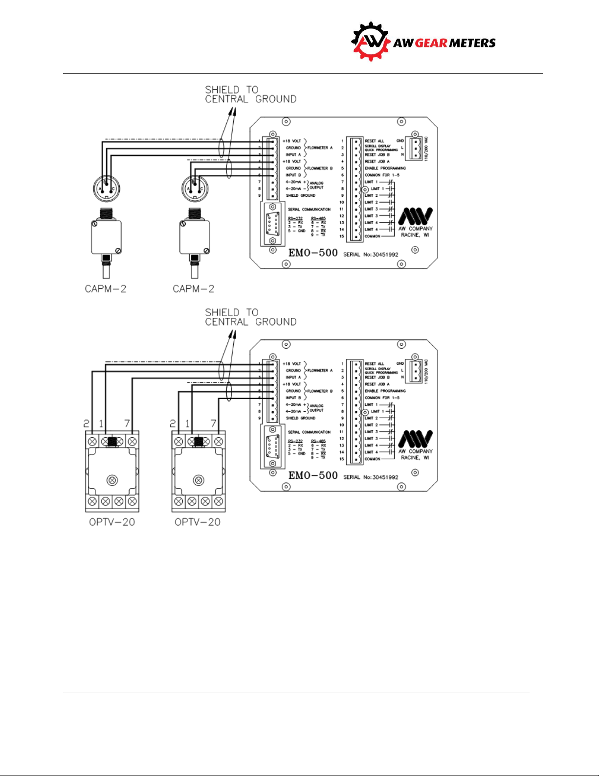
You will connect three wires from each of the two sensors to the back of the EMO-500 (see samples next
page):
Insert the two red wires (electrical power) to the two +18 volt terminals
Insert the two white (signal) wires to the input terminals
Insert the two black (ground) wires to the ground terminals
Use a screwdriver to secure.
Color of wires may vary.
Connect the higher flow side to flow meter A as the Ratio calculation is A/B.
5
Page 7
EMO-500
Operation and Programming Manual
Figure 1: Sample pickup connections
6
Page 8
EMO-500
Warning!
Operation and Programming Manual
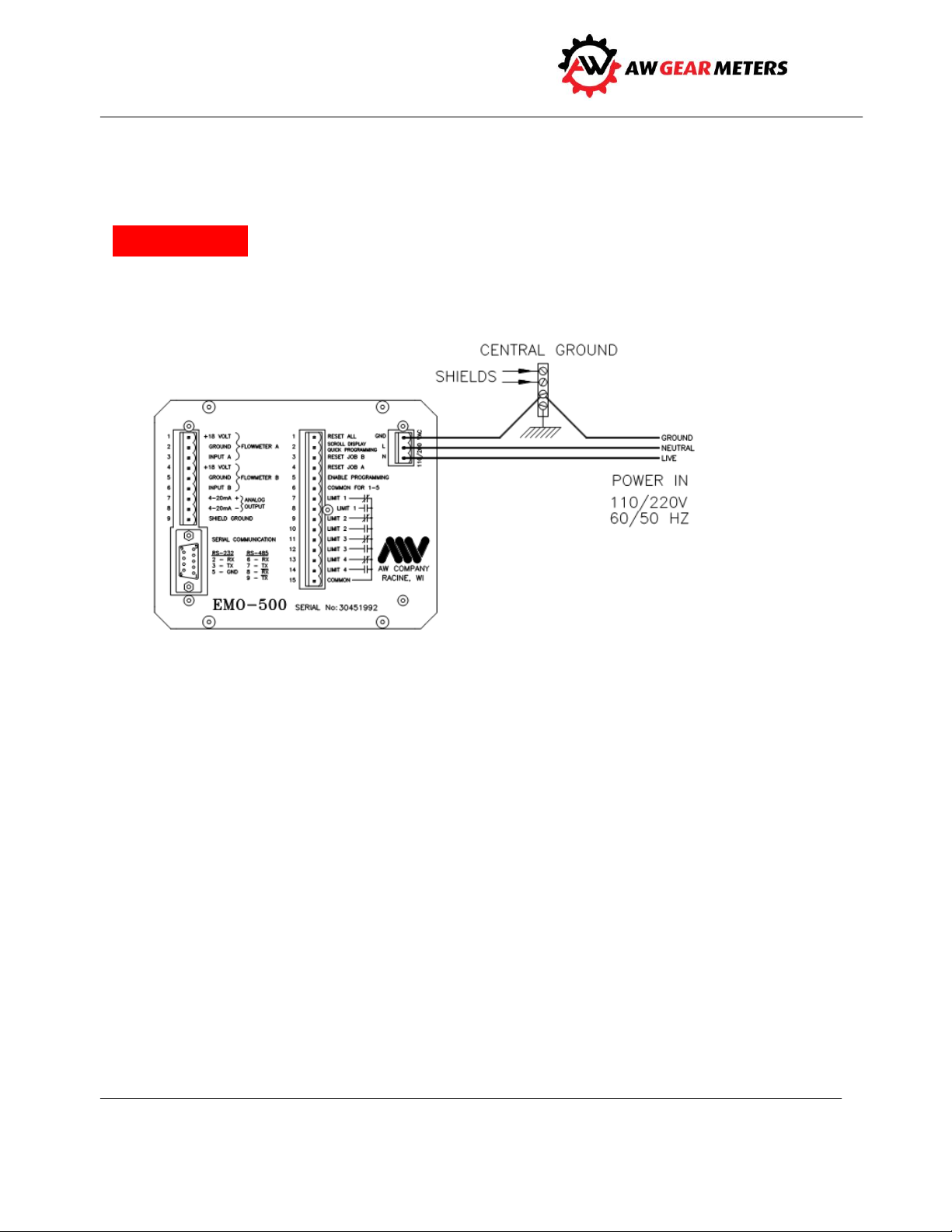
Connect Unit to Power
Before connecting to power source, connect ground, neutral and live wires to terminals on back of the
EMO-500 (see diagram below). See shielding information on page 11.
Connect wires to back of unit before applying power and wire the unit only as described on label on back
of unit.
Figure 2: Connections to power
7
Page 9

EMO-500
0-KEY = = =>
RATIOA/B = 1.19
W=Y A=N I = 1.00
= = => Current Ratio A/B
= = => Warning, Alarm, Ideal Ratio
1-KEY = = =>
FLW A=139.3 CCM
FLW B=136.3 CCM
= = = > Flow A
= = = > Flow B
2-KEY = = =>
JOB A=10779. CC
JOB B=11703. CC
= = = > Job Total A
= = = > Job Total B
3-KEY = = =>
GR A=300912. CC
GR B=313391. CC
= = = > Grand Total A
= = = > Grand Total B
4-KEY = = =>
J A+B 614303. CC
G A+B 623476. CC
= = = > Job Total (A+B)
= = = > Grand Total (A+B)
5-KEY = = =>
CURRENT RATIO LI
WAR=005% ALA=010%
= = = > Ratio Warning/Alarm Settings *
6-KEY = = =>
SD1: AO=0000
IN=11111OUT=0000
= = = > Analog Out, 0-4095 = 0-20mA
= = = > Inputs pins 1-5, Limits Out
7-KEY = = =>
SD2:FA=139FB=136
TA=10779TB=11793
= = = > Frequency A, B .....(Hz)
= = = > Total Impulses A, B
8-KEY = = =>
RATIO A/B=1.19
FL A+B 275.6 CCM
= = = > Current Ratio A/B
= = = > Flow Rate (A+B)
9-KEY = = =>
L1 L2 L3 L4
OFF OFF ON ON
= = = > Limit Status
F1-KEY ===>
T A-B= 24321. CC
F A-B= 15.4CCM
= = = > Total Differences
= = = > Flow Differences
*
Operation and Programming Manual
Overview of Display Screens
The 0 through 9, and F1 keys display these screens except when programming.
A no Ratio Mode when Limit 2 Rule is not on Ratio
8
Page 10

EMO-500
Operation and Programming Manual
Product Description
For use in steady or pulsing streams, the EMO-500’s primary purpose is to monitor the flow rates of two
flow meters, measuring flow rates, comparing totals, and verifying the ratio of flow A to flow B. You can
also wire an alarm to the EMO-500 so it can alert you to fluctuations from normal.
The unit comes from the factory with default values already programmed. However, if programming
parameters require change, you can input data from the front keypad; you can also do this from a
computer.
You can “Quick Program” the EMO-500, or take advantage of the Full Programming option. Program
keys are in red on the unit’s keyboard (some keys have a dual function). You can also program the EMO-
500 through the unit’s serial port. As a security measure, you can block access to programming when in
the Full and Serial Port programming modes.
Features
Seven different totalizers for record keeping and reports
Nine programmable units of measure
Net consumption display
“Ready-to-Hardwire” function controls allow for remote resets, operation of displays, and
Quick/Full Programming
Four programmable relay switched limits for warnings, alarms, or automatic shut-down control
RS-232 and RS-485 serial ports
Analog outputs (4 - 20mA) and (0 - 5V)
Principle of Operation
After you connect two flow meters to the unit and power it up, the EMO-500 can begin monitoring flow,
totals, and ratios. Monitor data on-screen; fine tune and adjust programming parameters as needed.
Technical Data
Key Programming Features
Ideal Ratio: user-defined, compared to actual ratio
Gate Time: time-before-the-flow rate display updates
Sample Size: number of pulses counted before ratio updates
Limits: Ratio, Flow Rate and Total
Units of Measure: liter, cc, gal, oz, gr, kg, lb, rpm, Hz
Technical Information
Power Supply: input = 110 or 220 VAC; consumption = 4 watts
Communication: type = RS-232 and RS-485; protocol type similar to OPTO 323
9
Page 11

EMO-500
Operation and Programming Manual
Environmental: storage = -40°C to 85°C; operating = 0°C to 50°C; humidity = 10 to 90%, non-
condensing
Limits: 10 amp, 110 V dry contact relays
Display Information
Ratio (ideal): Flow Rate A, Job Total A, Grand total A
Ratio (actual): Flow Rate B, Job Total B, Grand Total B
Limit Settings: Flow Rate A+B, Job Total A+B, Grand Total A+B
Limit Status: Flow Rate A-B, Job Total A-B
Special Features
The EMO-500 is geared toward applications where the main interest is the ratio of components
dispensed over a period of time, for example in a batch, rather than monitoring on an instantaneous
basis. The unit is especially suited for use in dispensing systems with irregular flow patterns. The EMO500 features a programmable sampling size, which governs how often the ratio display updates and
provides maximum control over the sampling period. The EMO-500 is easy to adjust to suit system
parameters.
Helpful Information For Using the EMO-500
Sample Size
This is the number of impulses collected for the ratio calculation. To determine the ratio, the EMO-500
separately counts the total number of pulses from both flowmeters until the fastest one reaches the
SAMPLE SIZE. The EMO-500 divides the number of pulses flowmeter A produces by flowmeter B’s
pulses, and the result is the ratio. The accuracy and response time of the ratio calculation is therefore
dependent upon the SAMPLE SIZE. The flowmeter with the lowest pulse rate should produce 100 pulses
before the ratio calculation updates to achieve a 1% accuracy. Default value is 200. The display screen
#7 is a useful guide for this purpose.
Gate Time
This is the time period over which the EMO-500 makes Rate Calculations. The gate time (in seconds) is
the time period during which the microprocessor collects pulses to perform rate calculations. Default
value is 1.85.
Serial Port Programming
You can program the EMO-500 through the serial port using RS-232- or RS-485-type communication.
Refer to the Serial Port Operations on page 31 for complete information.
10
Page 12
EMO-500
Warning!
Operation and Programming Manual
Hardware Connections
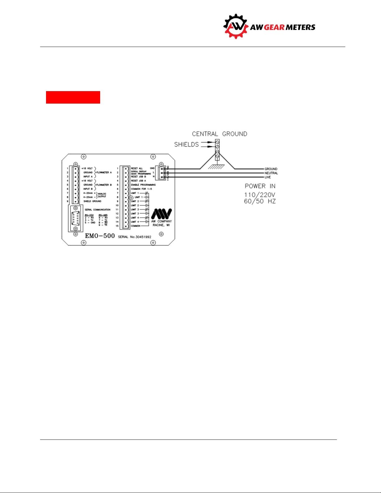
Before connecting to power source, connect ground, neutral and live wires to terminals on back of the
EMO-500: PIN 1= ground, PIN 2 = line 110 or 220 V, and PIN 3 = line neutral (see Figure 3).
Wire the AC power only as labeled on the three pin connector.
Figure 3: Connections to power
Grounding Considerations
The grounding is a most important consideration in an installation where microprocessor technology is
applied. The EMO-500 is a panel-mounted unit where the casing connects to a sub-panel. If the
sub-panel is metal, it should be grounded. If the sub-panel is made of non-conductive material, PIN 1 of
the three-pin connector on the EMO-500 back panel must be grounded. To insure a proper ground, the
factory recommends connecting PIN 1 of the three-pin connector to the panel's central ground point.
Signal and Shielding
The two flow meter pickups should be supplied with their respective 18-volt supply voltages and
referenced to their respective grounds. This insures the input signals from the flow meters are
referenced to the ground connections on pins 2 and 5. Most applications require some signal shielding;
a solid-aluminum wrap shielding works well. Connect the shield to pins 2 and 5 on the flow meter
connector. DO NOT connect the shielding at the flow transmitter.
11
Page 13
EMO-500
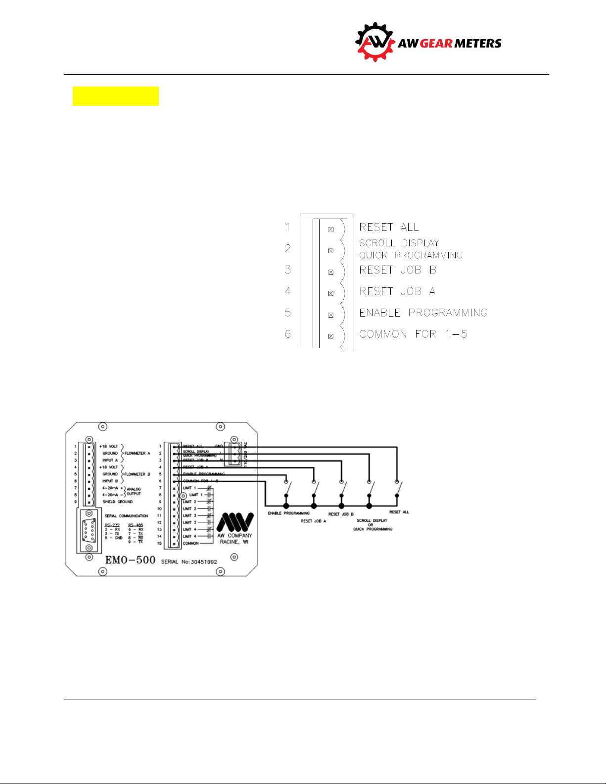
Figure 4: Connecting five inputs to common
Caution
Figure 5: Pin 1-4 and Pin 5 connections
Operation and Programming Manual
Never connect the shield to ground at both ends. Doing so can produce unwanted oscillations in the
signal wires.
External Resets and Controls (Hardware)
Five inputs to the 15-pin connector help provide extra control without having to go through the
keyboard. To activate the external resets and controls, connect the respective pin to the “Common for 1
– 5” pin. See Figure 4.
Pins 1 - 4 are edge-triggered; use
momentary contact switches to activate
them. Pin 5 (enable programming) is an
on/off function; use a single-pole toggle
switch for it. See Figure 5.
12
Page 14

EMO-500
Notice
Notice
Operation and Programming Manual
External Resets and Controls (Definitions)
Reset All
This reset is the most powerful on the EMO-500. It resets:
Ratio A/B
Job Vol A, Job Vol B and Job Vol A+B
Warning and Alarm Limits
Limits 3 and 4
Grand Totals
Analog Outputs to start point
Scroll Display
This input scrolls through all of the 11 screens available. It also allows access to the Quick Programming
functions, which are highlighted in red on the upper keypad line. (See page 14 for more details on Quick
Programming).
Reset Job B - resets OFF-RATIO WARNING/ALARM (LIMIT 1 and 2)
This input resets the Job B totalizer. It also resets the A/B RATIO to the IDEAL setting, which
simultaneously resets the WARNING and ALARM LIMITS.
Reset Job A - resets OFF-RATIO WARNING/ALARM (LIMIT 1 and 2)
This resets the Job A total. It also resets the A/B RATIO to the IDEAL setting, which simultaneously resets
the WARNING and ALARM LIMITS.
Simultaneously pressing and holding RESET JOB A and RESET JOB B on the keyboard, or through the
back-panel connections, actuates HOLD TOTAL.
Enable Full Programming
Enables the F2 through F6 keys to perform the programming functions shown in red on the banner strip
above the keypad.
F3, F4, and F5 serve as Job Resets in the Job Totals screen when the Enable Programming switch is OFF.
13
Page 15
EMO-500
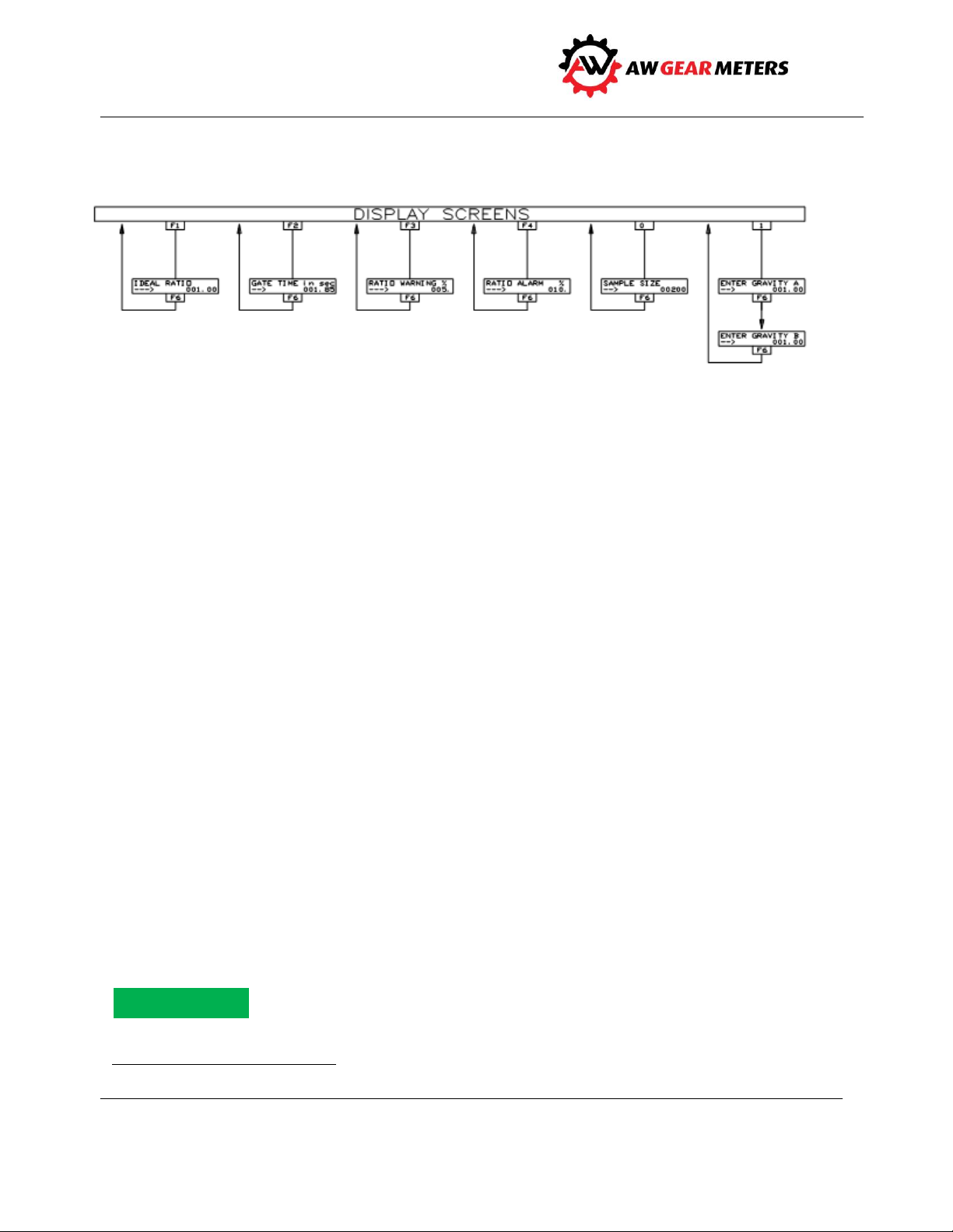
Figure 6: Quick Programming Display Screens
†
Notice
Operation and Programming Manual
Quick Programming
Many programming variables such as KFR† or meter selection only require a "one time" setting; other
variables require some experimentation to find maximum efficiency settings. It is also desirable to allow
field personnel the limited ability to make some quick adjustments.
To accommodate these circumstances the EMO-500’s "Quick Programming" option allows you to jump
directly into some limited programming functions. These functions are noted in red on the keypad on
the top line of function keys F1 through F6, and the 0 and 1 keys (also see Figure 6). The keys and their
functions are:
F1 = Ideal Ratio
F2= Gate Time
F3 = Ratio Warning %
F4 = Ratio Alarm %
F5 = Decimal Point
F6 = Enter
0 = Sample Size
1 = Specific Gravity
Activation
To activate Quick Programming, connect the Scroll Line Input (Pin 2) and the “Common 1 – 5” (Pin 6) of
the 15-Pin connector on the back panel of the EMO-500 with a momentary contact switch. With this
connection established, push any one of the above keys.
This does not work if full programming is enabled.
A rate scaling factor.
14
Page 16

EMO-500
Operation and Programming Manual
Figure 7: Sample Connections, Inputs and Outputs
15
Page 17

EMO-500
Operation and Programming Manual
Keys and Values
F1 Ratio (Default Value = 1.00)
This function is the address of the IDEAL RATIO, which represents the desired ratio of FLOW A/FLOW B.
The default is 1.00, which represents a 1 to 1 ratio.
F2 Gate Time (Default Value = 1.85)
The GATE TIME is the period of time, in seconds, during which the EMO-500 calculates the flow rate. The
accuracy and response time of the flow rate display is therefore dependent upon this value. To achieve a
1% accuracy, the slowest pulse rate should deliver at least 100 pulses.
F3 Warning (Default Value = 5%)
The WARNING variable is set as a percent deviation from the Ideal Ratio. The first meter to deliver the
number of pulses programmed as the SAMPLE AMOUNT triggers the ratio calculation. The calculation
compares the measured ratio to the Ideal Ratio; if the difference in percent exceeds the programmed
value, the warning activates.
F4 Alarm (Default Value = 10%)
Similar to the above Warning variable.
F5 DP (Decimal Point)
Use this key to locate the decimal point when programming the EMO-500.
F6 Enter
Use this key to lock in programmed values.
#0 Sample Size (Default = 200)
To determine the ratio, the EMO-500 separately counts the total number of pulses from both
flowmeters until the fastest one reaches the SAMPLE SIZE. The EMO-500 divides the number of pulses
flowmeter A produces by flowmeter B’s pulses, and the result is the ratio. The accuracy and response
time of the ratio calculation is therefore dependent upon the SAMPLE SIZE. The flowmeter with the
lowest pulse rate should produce 100 pulses before the ratio calculation updates to achieve a 1%
accuracy. The display screen #7 is an useful guide for this purpose.
#1 SG (Specific Gravity [Default = 1.0])
If needed, enter specific gravity values for each metered flow.
16
Page 18

EMO-500
ESCAPE
ACCESS
RATIO
LIMITS
METERS
GLOBALS
PROGRAMMING
Notice
Notice
Operation and Programming Manual
Full Programming
The three methods of programming the unit are:
Quick Programming
Full Programming, and
Serial Programming
You can change all of the default program variables to alternative values through the keypad or by a
host computer with an RS-232 serial port.
For information about Quick Programming, go to page 14. For information about Serial Programming, go
to page 31. See below for Full Programming instructions.
Full and Serial Programming have lockout features to prevent unauthorized access.
Enable
Quick Programming functions allocated to certain keys are in red on the keypad. Keys F1 through F6
have multiple functions and are also used for Full Programming. A banner on the keypad immediately
above specific keys indicates the alternative function each key has in the Full Programming Mode.
When full programming is not enabled, F3/F4/F5 serve as Job Resets, and you can use keys 0 through 9
to select from the 11 operating displays shown on page 8. IMPORTANT: The higher flow side should be
connected to flow meter A as the Ratio calculation is A/B.
To access the Full Programming menu, place a jumper between pin 5 (enable programming) and pin 6
(common). Use the F2 key to page through the menu of programming options, which are indicated in
red lettering on a banner above the upper function keys (representation below).
As a security measure, access is denied to F3, F4, and F5 until you press F2 first.
Reminder: Quick Programming activates the functions indicated in red on the F1 - F6 and 0 - 1 keys. See
page 14.
After jumpering pin 5 to pin 6, the access sequence is:
17
Page 19

EMO-500
MAIN MENU
F2
OPTIONS
Enable Prog --> F2
-->
-->
-->
-->
F3
F4
F5
F6
(Access to Ratio Prog)
(Access to Limit Prog)
(Access to Meter/Units)
(Access to Global Prog)
Operation and Programming Manual
F3 F4 F5 F6
RATIO PRG. LIMIT PRG. METER/UNIT PRG. GLOBALS PRG.
F1
Serves as an ESCAPE key to leave the programming functions and return to the last screen displayed.
F2
Pages you through the programming options above AND IS REQUIRED TO ALLOW FURTHER ACCESS.
F3
Ratio programming (see below):
18
Page 20

EMO-500
Notice
Operation and Programming Manual
Enter the Ideal Ratio. This number
represents the desired Ratio of Flow
Amount A to Flow Amount B. The
default is 1.00, meaning a 1 to 1 ratio.
Enter the Ratio Warning. This number
represents the percentage of error
between the actual measured ratio
and the desired ideal ratio. The default
is 5%; therefore, if the actual and
measured ratio differ by more than
5%, the Limit 1 relay closes.
Enter the Ratio Alarm. This number
works the same as Ratio Warning
except that after the warning, the
EMO-500 waits for one more sample
amount before closing the Limit 2
Relay if the ratio error is greater than
the programmed percentage. Default
is 10%.
F4
Limit programming.
Off-Ration Warning and Alarm Settings
Since the EMO-500 is primarily a Ratio Monitor, Limits 1 and 2 are factory-set, which an “off” condition
triggers.
Default values are:
Limit 1 = Warning 5%
Limit 2 = Alarm 10%
For example, if you program the RATIO WARNING at +/- 10%, the LIMIT 1 contact closes when this event
occurs. The programmed value similarly activates LIMIT 2 in the RATIO ALARM.
Press key #5 to review the current ratio alarm settings and key #9 to review the limit status. Press either
F3 (Reset A) or F4 (Reset B) to reset off-ratio alarms.
19
Page 21

EMO-500
Operation and Programming Manual
As mentioned previously, Limits 1 and 2 are preset for ratio alarms, which you can easily adjust for
different ratio settings via Quick Programming.
Adjust Limits 3 and 4
Limits 3 and 4 are used to warn of other monitored parameters such as flow rates or totalized fluid
volumes. Adjust these settings as follows:
Three parts make up the Limit Programming section; do each part in order:
1. Limit 3 Rule and value
2. Limit 4 Rule and value
3. Limit 2 Rule and/or value
20
Page 22

EMO-500
Notice
Notice
Operation and Programming Manual
This procedure is also shown pictorially on the previous page.
1. Enter the “Limit 3 Rule.” This means you must select the function to trigger the Limit 3 relay.
Options are:
Job Total for A
Job Total for B
Job Total for A+B
Flow A
Flow B
Flow A+B
Press F4 to page through the options; press F6 to enter your selection.
The display flashes “DP Location Will Match KFT/KFR.” This means the number you entered for the Limit
trip point automatically takes the same decimal point location as the Total Scaling Factor (KFT) for Total
Limits, or Rate Scaling Factor (KFR) for Flow Rate Limits.
2. Type in the Limit 3 value; press F6 to enter (you must enter the Limit 3 number to proceed to
Limit 4).
3. Enter the Limit 4 Rule and number exactly as above (you must enter the Limit 4 number to
proceed to Limit 2).
4. Enter the Limit 2 Rule.
If you select Ratio A/B, the Limits 1 and 2 operate on the ratio percentage of error under F3 Ratio
Programming. Therefore, if you select Ratio A/B, limit programming is complete.
In another scenario, you can program Limit 1 and 2 for Warning and Alarm settings on Flow A, while you
can allocate Limit 3 and 4 to Warning and Alarm for Flow B or Flow A+B and Total B, respectively. In this
case, you can select Limits 3 and 4 independently but you cannot separate 1 and 2.
Other options are as follows (page using F4; enter, F6):
Ratio A/B
Job Total for A
Job Total for B
Job Total for A+B
Flow A
21
Page 23

EMO-500
Flow Meter
Approximate K-factor
ZHM01
160000 PPG
ZHM03
6600 PPG
HPM-15
32000 PPG
ZHM02
1.32000 PPG
ZHM04
1800 PPG
HPM-20
16000 PPG
ZHM02
16000 PPG
ZHM05
500 PPG
HPM-30
6600 PPG
Notice
Operation and Programming Manual
Flow B
Flow A+B
If you select any function other than Ratio A/B for the Limit 2 Rule, the EMO-500 still monitors the ratio
of flow A/B, but no Warning or Alarm trips when flow is out of the error percentages. Display 5 indicates
“NO RATIO MODE FOR LIMITS 1 & 2.”
F5
In the Meters/Units programming section, you select from nine Flow Meters and three Engineering
Units. Scroll through the Meters until the selection desired appears on the display and enter your
selection with the F6 key. The EMO-500 automatically enters the Rate Scaling Factors (KFR) and Total
Scaling Factors (KFT) for each of the selections below.
The unit then asks you to select the Engineering Units in the same manner. Choose from:
CC & CCPM
GAL & GPM
OZ & OZM
The EMO-500 flashes “Direct Selection, Meter A or B” and the display reads “F2=A, F3=B, F4=A&B.” This
is where you choose the Flow Meter and set the Engineering Unit. The display reads “More Selections?,
F2=Yes, F3=No.” If both Flow Meters are programmed, select F3; if not, press F2 to start the
Meters/Units Program section again.
22
Page 24

EMO-500
Notice
Notice
Operation and Programming Manual
The Engineering Units for A and B should be the same.
The KFR and KFT values in Meters/Units Programming are only approximations because the K-factors of
the above flow meters are only approximations. Calculate the (KFR) and (KFT) using the calibrated
K-factor whenever possible. See the Global Programming section on page 24.
23
Page 25

EMO-500
Global Default Values
1.
KFR for A
-----------
100.0
2.
KFT for A
-----------
10000
3.
KFR for B
-----------
100.0
4.
KFT for B
-----------
10000
5.
Units for Rate
-----------
12 Hz
6.
Units for Total
-----------
08 impulses
7.
Sample Size
-----------
200 impulses
8.
Gate Time
-----------
1.85 seconds
9.
Analog Offset
-----------
0000
10.
Analog Gain
-----------
10200
11.
Analog Rule
-----------
06 Ratio
12.
Unit Number
-----------
01
Operation and Programming Manual
F6
The F6 key calls up Global Programming.
Explanation of Global Variables
1. KFR for A (Default 100.0)
In order to display the correct rate in an engineering unit such
as GPM, the EMO-500 must calculate a scaling factor. This Rate
Scaling Factor is called the KFR. The EMO-500 uses the K-factor
of the flow transmitter being monitored to calculate the KFR.
The K-factor is the number of impulses per engineering unit
established by a calibration test.
For example, a flow meter could have a K-factor of 6304
imp/Gal. To calculate the KFR multiplier for the EMO-500, apply
the following formula:
24
Page 26

EMO-500
Notice
Notice
KFT =
KFR =
100 is the constant for seconds
6000 is the constant for minutes
360000 is the constant for hours
= 2.921 GPM
KFR =
Operation and Programming Manual
6000
K -factor
Enter this KFR number in the Global Programming section. The K-factor is the number the manufacturer
provides as the average K-factor for the transmitter.
For example, a flow meter has the K-factor 2053.7 imp/GAL and the display should show
Gallons/minute.
6000
2053.7
Enter 2921 as the KFR; use the DP (decimal point) key to move the DP to the number 2.921.
Calculator mathematics produce insignificant decimal numbers for our purposes. These produce a
misleading level of precision in the display. The factory recommends using a maximum of four digits
regardless of the decimal point position.
Example:
for 60.675, enter 60.67
for 2.3456, enter 2.346
The largest number you can enter as a KFR is 65000, ignoring the decimal point position. A message
alerts you if the number you enter is too large.
2. FT for A (Default 10000)
In order to make the EMO-500 display the correct Totalized Value in Engineering Units, again the most
important thing to know is the K-factor of the flow meter. The K-factor is the relationship between the
amount of the impulses and the engineering units.
To calculate the KFT, apply the following formula:
K-factor
10000
25
Page 27

EMO-500
KFT =
= .9376 Gal
Notice
Notice
Operation and Programming Manual
Enter the KFT in the Global Programming section. The K-factor is the number manufacturer provides as
the average K-factor for the transmitter. If this is in imp/Gal, set the totalizer in, say cc’s , by converting
the K-factor to imp/cc. 10000 is a constant.
For example, a flow meter has a K-factor of 106666.0 imp/Gal and the display should show
gallons/minute:
10000
10666.0
Enter 9376 as the KFT and move the DP to 0.937. (See note below).
Calculator mathematics produce insignificant decimal numbers for our purposes. These produce a
misleading level of precision in the display. The factory recommends using a maximum of four digits
regardless of the decimal point position. For example, for 60.675, enter 60.6; for 2.34543, enter 2.345
The largest number you can enter as a KFT is 65000. Refer to KFR note above.
3. KFR for B
The same as KFR for A.
4. KFT for B
The same as KFT for A.
5. Units for Rate.
This variable displays the Engineering Units required for the flow rate display. It is strictly a display and
does not perform the actual conversion of raw counted impulses; the KFR handles those calculations.
Enter the two-digit number for the desired Units for Rate:
00 - cc/min 06 - gram/sec
01 - liter/min 07 - lb/min
02 - gallon/min 08 - Kg/min
03 - ounce/min 09 - Kg/sec
04 - RPM 10 - lb/sec
05 - gram/min 11 - lb/Hr
12 - Hz (impulses/sec)
26
Page 28

EMO-500
Notice
Operation and Programming Manual
6. Units for Total.
This variable determines the Engineering Units for Total displayed after the totalizer value. It too is a
“display only” function and does not perform the actual conversion of total impulses to the correct
value. The KFT handles those calculations.
Enter the two-digit number for the desired Units for Total:
00 - cc 04 - revolution
01 - liter 05 - gram
02 - gallon 06 - lb
03 - ounce 07 - kg
08 - impulses
7. Sample Size (Default 200)
To determine the ratio, the EMO-500 separately counts the total number of pulses from both flow
meters until one of them reaches the programmed Sample Size. The number of pulses from flow meter
A is then divided by the number of pulses received from flow meter B. The accuracy and response time
of the ratio calculation are therefore dependent on the Sample Size.
To determine a reasonable number to program for Sample Size, the main factor is the flow meter with
the lowest pulse rate, but with at least 100 pulses before the Ratio calculation. If 100 pulses are counted
on the slowest moving totalizer then the accuracy of the ratio calculation should be about 1%.
The pulses counted are straight from the flow meter, not scaled engineering unit values.
The display screen #7 (Status Display 2) is a useful guide in this selection. The lower line shows the
incoming raw pulse count. For example, if the Sample Amount is 1000, the ratio display updates each
time the fastest total increments by 1000. Also by this method, the slower pulse count can be observed.
Default value is 200.
8. Gate Time (Default 1.85 sec.)
The gate time (in seconds) is the amount of time pulses are accepted before the EMO-500 performs flow
rate calculations. The accuracy and response time of the flow rate display are dependent on the gate
time. To achieve a 1% flow rate accuracy, the lowest pulse rate should produce 100 pulses before the
device performs the rate calculation. In display #7 (Status Display 2), the lower line indicates incoming
flow meter impulses, an estimate of the time elapsed for 100 pulses, to be accumulated by the slowest
meter, which gives a good approximation of the minimum recommended gate time.
27
Page 29

EMO-500
Analog Ouput =
GAIN =
GAIN =
Operation and Programming Manual
Another method is to change the default Gate Time value by trial and error until achieving the best
results.
9. Analog Offset (Default 0000)
The Analog Output Offset is a number from 0000-4095 that becomes the bottom end of the 0 - 5 volt
and 4 - 20 mAmp analog outputs.
For example:
0000 for 0 to 20mAmps and 0 to 5v.
819 for 4 to 20mAmps and 1 to 5v.
1638 for 8 to 20mAmps and 2 to 5v.
2457 for 12 to 20mAmps and 3 to 5v.
10. Analog Gain (Default 10200)
The analog gain factor integrates the controller output range and speed with the rest of the system
capabilities. If the gain factor is correct, the full range of the analog output signal can be used to cover
the operating range of the equipment in which it is installed.
Use this formula to determine the analog output:
(Variable Value) X Gain
512
The Analog Output arrived at above should be a number from 0000-4095, which drives a D/A converter
for a 4 - 20 mAmp and a 0 - 5 volt output on Pins 7 and 8 of the 9 Pin connector. Therefore the gain
factor can be estimated by re-arranging the analog output equation as follows:
(512) (Analog Out)
Variable Value
If the desired maximum output of the system is achieved at 5V or 20 mAmp, this is equivalent to an
Analog Out value of 4095 and the above equation would read:
(512) (4095)
Variable Value
The “Variable Value” is the true flow rate or volume capability of the system measured at the analog
value discussed above and therefore depends upon the ANALOG RULE selected. The Analog Rule is
discussed further below.
28
Page 30

EMO-500
Notice
Notice
Operation and Programming Manual
The value you enter ignores the decimal point position.
For Example:
In Ratio Mode (06)
If Ideal Ratio = 5.00, variable value = 500
If Ideal Ratio = 10.00, variable value = 1000
In Flow Mode (00-02)
If Flow Rate = 80.0 cc/m, variable value = 800
If Flow Rate = 200.0 cc/m, variable value = 2000
If Flow Rate = 5.25 GPM, variable value = 525
In Flow Mode (03-05)
If Total Flow = 10.00 Gal, variable value = 1000
11. Analog Rule (Default 06)
The analog rule allows you to set the analog output to follow any of the variables listed below. Enter a
number as the Analog Rule.
00 - Flow A 06 - Ratio
01 - Flow B 07 - Ratio Feedback Mode
02 - Flow A+B 08 - Ratio w/Reset
03 - Total A 09 - Ratio Feedback w/Reset
04 - Total B 10 - A - B Job Total
05 - Total A+B 11 - A - B Flow Rate
These variables are used in the computations as numbers in Engineering Units (ccpm, gals, ozs., etc.).
This means that any Decimal Points are dropped. For example, 113.7ccpm is 1137 for computation
purposes.
29
Page 31

EMO-500
Operation and Programming Manual
12. Unit Number (Default 001)
This variable is used for Serial Communication with a host computer. It identifies each EMO-500 unit if
there is more than one on the communication line. Unit #1 is 01, unit #2 is 02, etc.
Default Values Throughout the EMO-500
Ratio Programming
Ideal Ratio = 1.00
Ratio Warning = 5%
Ratio Alarm = 10%
Limit Programming
Limit Rule 3 = Job Total A, value = 3000
Limit Rule 4 = Job Total A, value = 4000
Meters/Units Programming
Meter = Hz
Units = IMPULSES
Global Variables
KFR for A = 100.0
KFT for A = 10000
KFR for B = 100.0
KFT for B = 10000
Units Rate = 12
Units Total = 08
Sample Size = 200
Gate Time = 1.85
Analog Offset = 0000
Analog Gain = 10200
Analog Rule = 06
Unit Number = 01
30
Page 32

EMO-500
Notice
Warning!
Operation and Programming Manual
Ratio Feedback Mode
The Ratio Feedback Mode compares the Ideal Ratio and the Actual Measured Ratio. The EMO-500
generates a 4-20 mA signal to control one of the Flow Rates. This maintains the Ideal Ratio over a wide
range of flow rates. The formula used to determine the correct analog output is:
Analog Output = Half Range + (Ideal Ratio-Actual Ratio) X Gain
Half Range refers to the middle point of the Analog Output. If the output varies from 0 to 20mAmp., the
half point is 10mAmp. If the Analog Offset is set to give an output of 4 to 20mAmp., the Half Point is
12mAmp.
To use the Ratio Feedback Mode, enter 07 as the Analog Rule (see page 29).
The Ratio Feedback Mode w/Reset works in exactly the same manner except that the analog output goes
to the start point (mid-point) on Reset All.
Serial Port Operations
The EMO-500 has standard RS-232 and RS-485 serial port connections on the 9-pin back panel. You can
connect this port to a host computer and then Read or Write to any memory location in the EMO-500.
The RS-232 pins on the 9-pin connector are:
pin 3 (TX transmit)
pin 2 (RX receive)
pin 5 (Ground)
The RS-485 connections are:
pin 6 (RX)
pin 7 (TX)
pin 8 (RX)
pin 9 (TX)
The communications port does not discriminate addresses. This means that any address can be written
to as well as read from. Writing to certain addresses changes the operation of the EMO-500 drastically.
Caution is a must when programming through a host computer. Double check addresses and variables
before writing to the EMO-500.
31
Page 33

EMO-500
Notice
Notice
Operation and Programming Manual
Communication through the serial port does not work if the EMO-500 is in programming mode.
Protocol Format
The EMO-500 uses a protocol format that follows OPTO 22 Company’s OPTOMUX.
^ means “add one letter or digit”; ^^ means add two letters or digits, ^^^ means add three letters or
digits, etc.; “cr” means “carriage return.”
The format for reading from the EMO-500 is as follows:
>01K0F3404XXcr
^................start of string must use the > sign
^^.............unit number (under global variables)
^.............read command K (use J to write)
^^^^......address to read from
^^......number of bytes to read
^^....checksum for the string 01K0F3404
......carriage return (ASCII 13) ends the string
The answer received back from the EMO-500 looks like this:
A03E36712XXcr
^...............all answers start with A
^^............low byte (at address 0F34)
^^..........next byte(at address 0F35)
^^........next byte(at address 0F36)
^^......high byte(at address 0F37)
^^....checksum
......carriage return ends the string
The protocol format for writing to the EMO-500 is as follows:
32
Page 34

EMO-500
Operation and Programming Manual
>01J03340F3587XXcr
^.....................start of string must use the > sign
^^..................unit number
^..................write command J (use K to read)
^^^^...........address to write into
^^...........byte written to 0334
^^.........byte written to 0335
^^.......byte written to 0336
^^.....checksum
.....carriage return
If the operation was successful, the EMO-500 answers with: Acr.
The following error messages have been implemented in the EMO-500 protocol:
NO1cr - Undefined command (something other than K/J)
NO2cr - Checksum error
NO3cr - Non printable ASCII character
OPTO 22 has published a booklet on the protocol format.
Checksum Calculation
The calculation for the string variables in the read command would be as follows:
>01K0F3404XXcr
^^^^^^^^^.......these characters are used in the calculation.
Add the values for the ASCII Decimal variables.
HEX 0 + 1 + K + 0 + F + 3 + 4 + 0 + 4
ASCII 48 + 49 + 75 + 48 + 70 + 51 + 52 + 48 + 52 = 493
To calculate the final checksum, convert the decimal number 493 into HEX (493=1EDh) and take the last
two characters (ED) for the checksum. The final string would look like this:
>01K0F3404Edcr
33
Page 35

EMO-500
Operation and Programming Manual
Important Points for Serial Communication
1. Serial communication is disabled if the EMO-500 is in programming mode.
2. All characters in the communication string should be in CAPITALS.
Example: the EMO-500 recognizes K is ASCII 75, but it does not recognize k is ASCII 107.
3. All numbers in the communication string are represented in hexadecimal format.
4. Do not try to read or write more than 12 bytes at a time due to limitations of the EMO-500's
serial buffers.
5. The least significant byte of a number is stored at the lower address.
6. The > in the transmit string and the A in the reply string are not used in the checksum
calculation.
The ASCII characters needed for checksum calculations are:
ASCII Decimal ASCII Decimal
0 48 A 65
1 49 B 66
2 50 C 67
3 51 D 68
4 52 E 69
5 53 F 70
6 54
7 55
8 56 J 74
9 57 K 75
34
Page 36

EMO-500
Address = 05A0H
05A1H
05A2H
05A3H
Vaule = 90H
D5H
89H
01H
Warning!
Notice
Operation and Programming Manual
The communications port does not discriminate any addresses. This means that any address can be
written to as well as read from. Writing to certain addresses changes the operation of the EMO-500
drastically. Caution is a must! Double check addresses and variables before writing to the EMO-500.
The bytes are always arranged such that the low byte (LSB) is first and the more significant bytes (MSB)
follow. In the EMO-500, the least significant byte is at the lower address. For example, if the data from
the totalizer is read as:
90D58901
the LSB is 90 and the MSB is 01.
The arrangement of these four bytes in the EMO-500 memory is:
Interpret the totalizer value as:
0189D590H = 25,810,320 (in decimal)
Address Information
When writing to the EMO-500, there are always two locations to be changed for a permanent entry into
the memory. This is because there are locations for data running currently in the RAM and for data that
is battery-backed. If the information has been written to the running locations alone, it is lost when the
EMO-500 is turned off.
Below is a QBASIC program that allows you to communicate with the EMO-500 by initiating serial port
#1 and prompting for read and write strings. The strings must use the OPTO 22 protocol format
described on page 32.
35
Page 37

EMO-500
Warning!
Operation and Programming Manual
DEFINT A-Z
'* Serial Communication Test Program for OPTOMUX Code
'* For use with AW Company's EMO-Series Flow Computers
'* Open serial port #1 to 9600 baud
OPEN "COM1:9600,N,8,1,RS,CS,DS,CD" FOR RANDOM AS #1
'* set up loop for transmitting several strings
CLS
DO
PRINT "Enter String to send. (Press ENTER alone to END)"
INPUT "Transmitting String: >", Transm$
IF LEN(Transm$) = 0 THEN END
'* Calculate Chksum
Chk = 0
FOR Char = 1 TO LEN(Transm$)
Chk = Chk + ASC(MID$(Transm$, Char, 1))
NEXT
Chk$ = HEX$(Chk)
'* Must be 2 characters, 1 byte
IF LEN(Chk$) < 2 THEN Chk$ = "0" + Chk$
'* Add the recognition character plus checksum
'* use only the last byte of checksum
Transm$ = ">" + Transm$ + RIGHT$(Chk$, 2)
'* Send it to the EMO
PRINT #1, ; Transm$; CHR$(13);
'* Read what the EMO sending back
LINE INPUT #1, Receive$
PRINT "Received: "; Receive$
PRINT
LOOP
The communications port does not discriminate any addresses. This means that any address can be
written to as well as read from. Writing to certain addresses changes the operation of the EMO-500
drastically. Caution is a must! Double check addresses and variables before writing to the EMO-500.
36
Page 38

EMO-500
Running
Address in HEX
Back-up
Address in HEX
Bytes
Description
Default Value
05F5
0402
2
KFR A
1000
061A
0404
2
KFR A Decimal Pt.
01
0637
0412
2
KFR A Eng. Units
00
05FF
040A
2
KFT A
10000
061C
040C
2
KFT A Decimal Pt.
00
0639
0414
2
KFT A Eng. Units
00
05F7
0406
2
KFR B
1000
061E
0408
2
KFR B Decimal Pt.
01
063B
0416
2
KFR B Eng. Units
00
0601
040E
2
KFT B
10000
0620
0410
2
KFT B Decimal Pt.
00
063D
0418
2
KFT B Eng. Units
00
050A
042D
2
Limit 1 Value
1000
050C
042F
2
Limit 2 Value
2000
050E
0422
2
Limit 3 Value
3000
0510
0424
2
Limit 4 Value
4000
060B
042C
2
Limit 1 & 2 Rule
06
0604
0429
2
Limit 3 Rule
00
0605
042A
2
Limit 4 Rule
00
0614 (4)*
042 2 Ideal Ratio
100
0618
0420
2
Ratio Alarm
10
0622
041E
2
Ratio Warning
05
059D
0437
2
Analog Rule
06
05AA
0433
2
Analog Gain
102000
05B9
0431
2
Analog Offset
0000
0606
041A
2
Sample Size
200
053D**
041C
2
Gate Time
1.85
0626
042C
1
Unit Number
001
0516
read only
4
Flow A
xxxx
051A
read only
4
Flow B
xxxx
051E
read only
4
Flow A & B
xxxx
05B5
read only
4
Ratio A/B
xxxx
05A0†
read only
4
Job Total A (SD2)
xxxxxxxx
05A6††
read only
4
Job Total B (SD2)
xxxxxxxx
05EF
read only
4
Job Total A + B
xxxxxxxx
052E‡
read only
4
Grand Total A
xxxxxxxx
0533‡‡
read only
4
Grand Total B
xxxxxxxx
0504
read only
4
Grand Total A & B
xxxxxxxx
05A4
read only
2
Analog Out
xxx
Operation and Programming Manual
37
Page 39

EMO-500
Operation and Programming Manual
Special variables (see previous page) function in the following manner:
*Ideal Ratio – The largest number that can be written into the Ideal Ratio without an overflow is 640.
Variable at address 0426h is 3 bytes; at 0614h, 4 bytes.
**Gate Time – This variable is a converted number because the keypad entry is made in seconds and a
constant must be applied for computations. Therefore after reading the Gate Time, the number read
must be converted to decimal, then divided by 5388 for an answer in seconds.
†Job Total A (SD2) – This variable shows twice the amount read from the Job A display. This is because
the number is actually a raw count from the frequency input. The number read matches the totals seen
in the Status Display 2 screen.
†† Job Total B (SD2) – Same as above.
‡Grand Total A – This variable is not stored into the backup memory until Job Volume A is reset.
Therefore, the location reads zero until the count is stored away with the Reset Job A.
‡‡ Grand Total B – Same as above.
38
Page 40

EMO-500
Operation and Programming Manual
Appendixes
39
Page 41

EMO-500
Operation and Programming Manual
40
Page 42

EMO-500
Operation and Programming Manual
41
Page 43

EMO-500
Operation and Programming Manual
42
Page 44

EMO-500
Operation and Programming Manual
43
Page 45

EMO-500
Operation and Programming Manual
44
Page 46

EMO-500
Operation and Programming Manual
45
Page 47

EMO-500
AW Gear Meters warrants the product to be in good working order for a period of 1 (one) year
from the date of purchase from AW Gear Meters or an Authorized AW Gear Meters distributor.
Should the product fail to be good working order at any time during this 1-year warranty period,
AW Gear Meters will, at its option, repair or replace the product at no additional charge except as
set forth below. Repair parts and replacement products will be furnished on an exchange basis and
will be reconditioned or new. All replaced parts and products become the property of AW Gear
Meters. This limited warranty does not include service to repair damage to the product resulting
from accident, disaster, abuse, or a non AW Gear Meters modification to the product.
Limited Warranty service may be obtained by delivering the product during the 1-year warranty
period to AW Gear Meters and provide proof of purchase date. If this product is delivered by mail,
you agree to insure the product or assume the risk of loss or damage in transit, to prepay shipping
charges to warranty location and use the original shipping container or equivalent.
For further information contact:
ALL EXPRESS AND IMPLIED WARRANTIES FOR THIS PRODUCT INCLUDING THE WARRANTIES OF
MERCHANTABILITY AND FITNESS FOR A PARTICULAR PURPOSE, ARE LIMITED IN DURATION TO A
PERIOD OF 1 (ONE) YEAR FROM DATE OF PURCHASE, AND NO WARRANTIES, WHETHER EXPRESS
OR IMPLIED, WILL APPLY AFTER THIS PERIOD. SOME STATES DO NOT ALLOW LIMITATIONS ON
HOW LONG AN IMPLIED WARRANTY LASTS, SO THE ABOVE LIMITATIONS MAY NOT APPLY TO
YOU.
IF THIS PRODUCT IS NOT IN GOOD WORKING ORDER AS WARRANTED ABOVE, YOUR SOLE
REMEDY SHALL BE REPAIR OR REPLACEMENT AS PROVIDED ABOVE. IN NO EVENT WILL AW
COMPANY BE LIABLE TO YOU FOR ANY DAMAGES, INCLUDING ANY LOST PROFITS, LOST SAVINGS
OR INCIDENTAL OR CONSEQUENTIAL DAMAGE ARISING OUT OF THE USE OR INABILITY TO USE
SUCH PRODUCT, EVEN IF AW GEAR METERS HAS BEEN ADVISED OF THE POSSIBILITY OF SUCH
DAMAGES, OR FOR ANY CLAIM BY ANY OTHER PARTY.
THIS WARRANTY GIVES YOU SPECIFIC LEGAL RIGHTS, AND YOU MAY ALSO HAVE OTHER RIGHTS,
WHICH MAY VARY FROM STATE TO STATE.
AW Gear Meters
8809 Industrial Drive
Franksville, WI 53126
Phone: (262) 884-9800
Fax: (262) 884-9810
Operation and Programming Manual
Limited Warranty
46
Page 48

8809 Industrial Drive
Franksville, WI 53126
800-850-6110
©2012 AW-Lake Company All rights reserved. Doc ID: EMO500MAN
www.awgearmeters.com
 Loading...