

Page 1
E-M
http://www.aw
FLOW
TRANSMITTERS
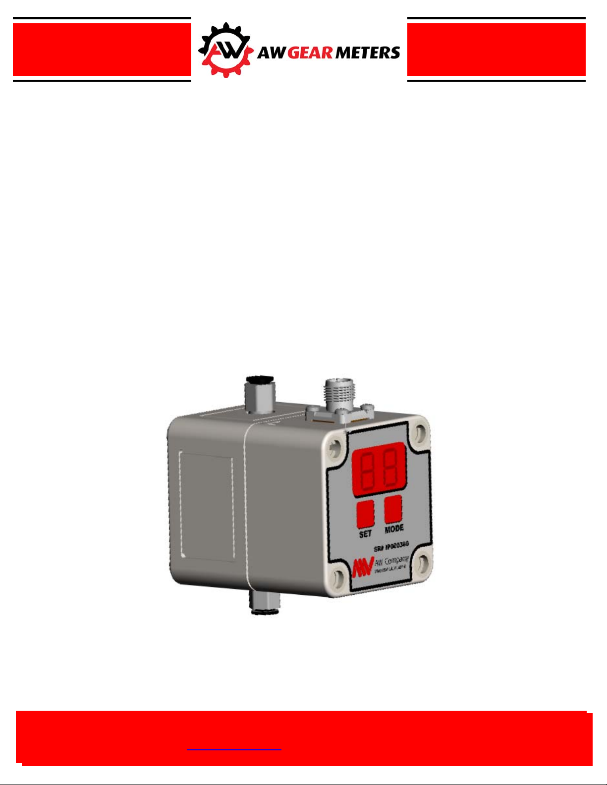
Digital Servo Pressure Control Valve
I/P Converter
IInnssttaallllaattiioonn && OOppeerraattiioonn MMaannuuaall
Rev 1.6
ELECTRONICS
FOR
8809 Industrial Drive, Franksville, WI 53126-9337
8809 Industrial Drive, Franksville, WI 53126-9337
Tel: 262-884-9800 Fax: 262-884-9810
E-Mail: awinfo@aw-lake.com Web: http://www.awgearmeters.com
ail: aw@awcompany.com Web:
Tel: 262-884-9800 Fax: 262-884-9810
company.com
Page 2

Installation….…………………………………………… page 3
Dimensions……….................………………….. page 3
Electrical Connections……….................………………. page 3
Connection for Voltage Control Input…...……... page 3
DSV-100 Start-Up……...……………….....…..……….. page 4
Setpoint……………..................………………… page 4
DSV-100 Input/Output Options…………………..…….. page 4
Response Test………………....................……… page 5
Manual Mode Operation………..………….……………. page 6
Digital Servo Pressure Control Valve
Model DSV-100
Installation and Operation Manual
Introduction / Features…..………..…………………….. page 2
Specifications…..………..………………….………….. page 2
Connection for Current Control Input ……..…... page 3
DSV-100 Display Modes.……………….....…..……….. page 4
Actual Pressure…………………............………. page 4
Difference………………………............………. page 4
Input Range Options …………...........…………. page 4
Output Range Options …………...........……….. page 4
Programming/Diagnostic Mode.…………….………….. page 5
View/Edit Input Option …………...........………. page 5
View/Edit Output Option …………...........…….. page 5
Leak Test……………………....................……… page 6
Limited Warranty Statement.............…………………… page 7
1
AW-Lake Company 8809 Industrial Drive, Franksville, WI 53126 web: www.awgearmeters.com
Tel: 262-884-9800 Fax: 262-884-9810 Email: awinfo@aw-lake.com
REV. 1.6 03/10 DSV-100 Manual.DOC
Page 3
2
Introduction / Features
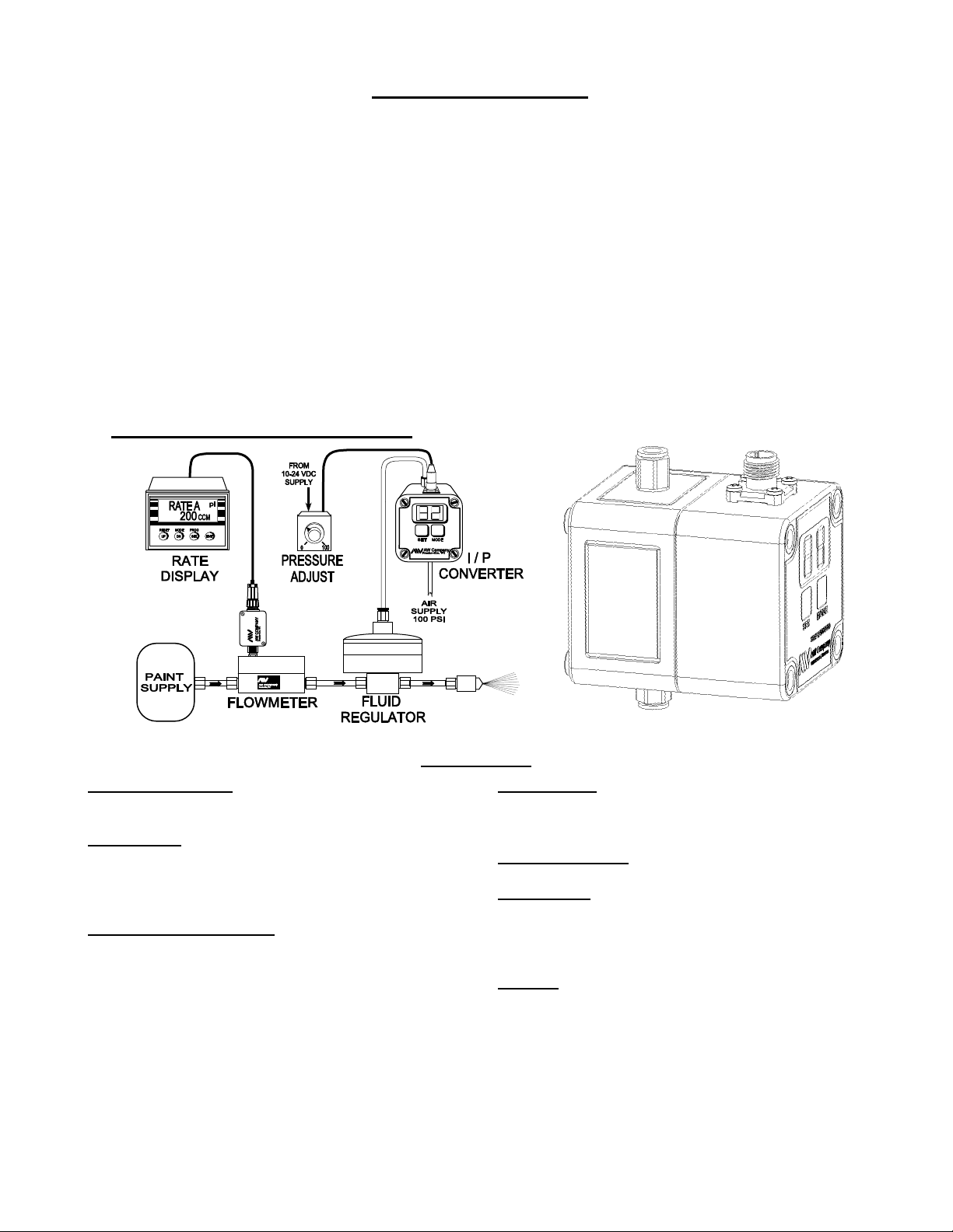
The DSV-100 I/P Converter from AW Gear Meters is a compact high performance digital servo pressure
control valve. Accepting either current, voltage or touch-key input, the I/P Converter precisely regulates
air pressure for directing process control valves and air or fluid regulators. This microprocessor-based
converter delivers high accuracy pressure regulation with extremely low dynamic response times for
improved process control and higher product quality. A highly visible integral LED display eliminates the
need for additional display components providing a display of actual pressure, set point pressure or the
actual pressure deviation from set point. Additional diagnostic test modes measure the system response
time or check for line leaks providing actual real-time data invaluable in commissioning, monitoring or
troubleshooting an installation. An analog output representing output pressure is provided. User set-up of
output pressure range and input voltage or current span is accomplished quickly and easily via the two
touch-keys and display. The lightweight and compact DIN rail mount package maximizes panel
component density while the push-in type ¼” pneumatic hose connectors and threaded electrical
connection minimize installation time and cost.
A Typical Spray Painting Application
Specifications
Power Requirements:
Supply Voltage 10 - 24 Vdc
Supply Current 85 mA. @ 15 Vdc
Signal Inputs:
Voltage Input (programmable) 0-5, 1-5, 0-10 Vdc
Voltage Input Impedance 10 KΩ
Current Input (programmable) 0-20 mA, 4-20 mA
Current Input Impedance 250Ω
Performance Specifications:
Max. Input Pressure 130 psig*
Output Psig (programmable) 3 to 15, 0 to 15,30,50, 100
Flow Rate, 100 psig @ Inlet .6 SCFM max
Recommended Filtration 20 Micron
Min. Closed End Volume 2.13 cu. in. (35 ml)
Linearity (typical) ± 0.1% F.S.
Hysterisis (typical) ± 0.1% F.S.
Repeatability (typical) ± 0.2% F.S.
Accuracy (typical) ± 0.3% F.S.
* Supply pressure should be 10% higher than max. required
output pressure, not to exceed 130 psig.
AW-Lake Company 8809 Industrial Drive, Franksville, WI 53126 web: www.awgearmeters.com
Tel: 262-884-9800 Fax: 262-884-9810 Email: awinfo@aw-lake.com
REV. 1.6 03/10 DSV-100 Manual.DOC
Signal Output:
Pressure Signal 0-5 Vdc
(Actual pressure, 0 to 100%
of programmed output range)
Dynamic Response:
10 - 90% F.S. Rated Output 180 ms.
Wetted Parts:
Elastomers RTV, Glass
Manifold Aluminum
Valves Nickel Plated Brass
Press. Transducer RTV, Aluminum, Plastic
Physical:
Operating Temp. Range 32-158°F (0-70°C)
Page 4

3
Installation
The DSV-100 has DIN rail mounting provisions on the back of the unit. Units can be mounted directly
beside each other for maximum panel component density. It is recommended to install the unit oriented
horizontally as shown below or vertically on it’s back. Air fittings are push-in type ¼” O.D. pneumatic
hose connectors.
Dimensions
Electrical Connections
Power and signal connections to the DSV-100 are through a 5-pin threaded circular connector (4-pin
connector on versions preceding 1.6). The use of shielded cable is recommended and the shield should be
connected to earth ground at the source. The DSV-100 requires a 10-24 VDC @ 35-136 mA supply for
operation. See specifications for complete voltage and current requirements. The DSV-100 will respond
to either voltage or current control determined by electrical connection and input option selection. See
Input/Output Options and Input/Output Options Programming on page 4 for input options. Voltage or
current control is referenced to Supply Common or the DSV-100 will accept a fully isolated mA input
when isolated mA input mode is selected in set-up. (On versions prior to 1.6 the –mA input must be
connected to supply common for proper operation when a current control input is used).
Connection for Voltage Input
* -mA Control Signal must be connected to the Supply Common for proper operation on DSV-100 versions
previous to 1.6. For version 1.6 and up isolated mA input operation is permitted when selected in set-up.
** Analog output available on version 1.6 and up only.
Electrical
10-24 VDC Supply
Supply/Signal Common
+ Volts Control Signal
No Connection
Analog Pressure Output**
Connection for Current Input
Electrical
10-24 VDC Supply
Supply Common*
+ mA Control Signal
- mA Control Signal*
Analog Pressure Output**
Connector
1
2
3
4
5**
Connector
1
2*
3
4*
5**
AW-Lake Company 8809 Industrial Drive, Franksville, WI 53126 web: www.awgearmeters.com
Tel: 262-884-9800 Fax: 262-884-9810 Email: awinfo@aw-lake.com
REV. 1.6 03/10 DSV-100 Manual.DOC
Page 5

4
DSV-100 Start-Up
The DSV-100 has several options for control input as well as several output range options that require setup before operation. To view and/or edit the input/output options see DSV-100 Input/Output Options on
this page and Programming/Diagnostic Mode on page 5.
DSV-100 Display Modes
After briefly indicating the operating software version, the DSV will always display the AP (actual
pressure) at power-up or after programming/diagnostics. The DSV-100 has three display modes:
AC - Actual Pressure – Displays the actual pressure in psi at the outlet port.
SE - Setpoint Pressure – Displays the set-point pressure in psi based on the analog input or manual set point.
di - Difference – Displays the difference in psi between the Actual Pressure and the Setpoint Pressure.
The MODE-key is used to change the display to another mode. When the MODE-key is touched the
display will briefly flash AC for actual pressure, SE for setpoint, or di for difference to indicate which
mode will be displayed. The DSV-100 will remain in the last selected display mode until the MODE-key
is used or the power is removed.
DSV-100 Input/Output Options
Input Range Options - The DSV-100 has six possible input options supporting 0-5, 1-5, or 0-10 volt
input, isolated or common grounded 0-20 or 4-20 mA input, or manual control of setpoint from the
keypad. The input options are assigned a number for programming as follows:
(01) 0-20 mA/0-5 volt (02) 4-20 mA/1-5 volt (03) Manual (keypad) Operation*
(04) 0-10 volt (05) 4-20 mA isolated input** (06) 0-20 mA isolated input**
** Options (05) and (06) for isolated mA input are only available on DSV-100 version 1.6 or higher.
For proper operation with DSV-100 versions previous to 1.6 the -mA Control Signal must be connected to
the Supply Common. Version number is displayed at power-up or in set-up mode.
Output Range Options - Five output range options are offered. The output range options are assigned a
number for programming as follows:
(01) 0-100 psi* (02) 0-50 psi (03) 0-30 psi
(04) 0-15 psi (05) 3-15 psi
*Manual operation will produce a 0-100 psi output range controlled directly from the front keypad. See
Manual Operating Mode on page 6 for more information.
The selected output range will always linearly represent the selected voltage or current input range and
pressure output is limited to maximum value of the selected range. The DSV-100 will respond to either
voltage or current control as determined by electrical connection (see Electrical Connections on page 3)
and input option setting. The DSV-100 default settings configure the unit for 0-20 mA/0-5 volt analog
input range (option 01) with 0-100 PSI output (option 01).
AW-Lake Company 8809 Industrial Drive, Franksville, WI 53126 web: www.awgearmeters.com
Tel: 262-884-9800 Fax: 262-884-9810 Email: awinfo@aw-lake.com
REV. 1.6 03/10 DSV-100 Manual.DOC
Page 6

5
Programming/Diagnostic Mode
To view or edit programmed input and output ranges and/or perform system diagnostic tests the
programming/diagnostic mode is used. Programmed input and output options are retained by the DSV100 indefinitely until edited. In the programming/diagnostic mode the input and output range options are
first presented for viewing or editing after which the DSV-100 performs a system response and leak test.
WARNING!! The DSV-100 will pressurize the system and perform a response and leak test after
the input and output range options are viewed or edited. This can cause unexpected motion, flow or
other physical response. Always use caution when using the programming/diagnostic mode and be
aware of the results it can produce.
To access programming/diagnostic mode, the SET-key must be pushed before and held in while power is
applied to the DSV-100. With the SET-key held in, apply power to the panel and/or plug in the electrical
connector to activate the converter. The DSV-100 will briefly show a software revision number before
entering the programming/diagnostic mode.
View/Edit Input Option - The display will blink ir (input range) five times and then display the
currently selected input option number for 2-3 seconds. If the desired option is displayed, do nothing and
wait a few seconds for the display to blink or(output range). If the displayed number is not the desired
input option, press the MODE-key immediately. The display will again blink ir (input range) five times
and display the next input option number. If the displayed number is not the desired input option, press
the MODE-key and repeat the procedure until the desired option number appears. When the desired
option is displayed, do nothing and wait a few seconds. The DSV-100 will save the last displayed
number as the input option and the display will then blink or (output range).
View/Edit Output Option - The same procedure is used to select one of five output range options. The
display will blink or (output range) five times and then display the currently selected output option
number for 2-3 seconds. If the desired option is displayed, do nothing and wait a few seconds for the
display to blink
MODE-key immediately. The display will again blink or (output range) five times and display the next
input option number. If the displayed number is not the desired output option, press the MODE-key and
repeat the procedure until the desired option number appears. When the desired option is displayed, do
nothing and wait a few seconds. The DSV-100 will save the last displayed number as the output option
and the display will then blink
Response Test - Once the input and output options have been viewed or edited the DSV-100 performs
two diagnostic tests, a response test and a leak rate test. The first is a dynamic response test and the
display will blink rP (for response test). The DSV-100 will first vent any pressure on the outlet then
pressurize the output to the maximum pressure dictated by the programmed output range for 100
milliseconds, read the system response, and display the result. Results appear as a number from 0 to 100%
with 100% indicating the best possible response. Responses will vary with length of hose and actuator
volume. Responses above 80% can be considered very good, a response below 50% indicate a low
response system. Lower responses can be due to long hoses, high volume components, excessive Cv
requirement, or may indicate a leak or malfunction.
rP (response test). If the displayed number is not the desired output option, press the
rP (response test).
AW-Lake Company 8809 Industrial Drive, Franksville, WI 53126 web: www.awgearmeters.com
Tel: 262-884-9800 Fax: 262-884-9810 Email: awinfo@aw-lake.com
REV. 1.6 03/10 DSV-100 Manual.DOC
Page 7

6
Leak Test - After a brief display of the response test result, the display will blink Lr (for leak rate) while
the DSV-100 performs a leak test. The DSV-100 pressurizes the output to the maximum pressure dictated
by the programmed output range and then reads the pressure for 2-3 seconds to determine if the system is
holding pressure or at what rate it is depleted. The leak rate is displayed as a number from 0 to 100% with
0% indicating a completely open output and 100% indicating that there is no leakage. A result less than
100% indicates that pressure has diminished over time likely due to a leak in a hose, fitting, diaphragm or
actuator. The leak rate result will be displayed for a few seconds and then the DSV-100 will then revert to
the AP display (Actual Pressure) and begin operation according to the programmed options.
Manual Operating Mode
When the manual operating mode is selected the default setpoint is 4 psi and the output range is 0-100 psi.
Whenever power is applied or after programming/diagnostics are completed the display will revert to the
AC display (Actual Pressure). As with analog input modes, the MODE-key is used to view the AC
(actual pressure), SE(set-point), or di (difference) displays. The two touch-keys are used to increment
(MODE-key) or decrement (SET-key) the setpoint value. To adjust the setpoint, press the SET-key
causing the display to blink SE(set) for 1-2 seconds. The DSV-100 looks for a key to be pressed before
SE stops blinking so quickly press and hold the MODE-key to increment the setpoint, or press and hold in
the SET-key to decrement the setpoint. Once either key is released, the SET-key must be pressed again
change the setpoint. In manual mode the DSV-100 will not retain the setpoint if power is removed and the
setpoint will always revert to four psi whenever power is applied or after programming/diagnostics are
completed.
AW-Lake Company 8809 Industrial Drive, Franksville, WI 53126 web: www.awgearmeters.com
Tel: 262-884-9800 Fax: 262-884-9810 Email: awinfo@aw-lake.com
REV. 1.6 03/10 DSV-100 Manual.DOC
 Loading...