

AWEA SP2016, SP3016, SP4016 OPERATOR'S MANUAL

AWEA SP/LP SERIES PROGRAMMER'S AND OPERATOR'S MANUAL (FANUC 18iMB) NO. SPEMFI13 DATE:2006/09/06
CNC DOUBLE COLUMN VER TICAL MACHINING CENTER
MODEL : SP2016/SP3016/SP4016
LP3021/LP4021/LP5021
LP4025/LP5025/LP6025
PROGRAMMER'S AND
OPERATOR'S MANUAL
VER. No.: SPEMFI13
AWEA MECHANTRONIC CO., LTD.
AWEA
DOUBLE COLUMN
VERTICAL MACHINING CENTER

PROGRAMMER'S AND OPERATOR'S
AWEA
MANUAL
VERSION : NO. SPEMFI13
EDITOR : Eric, Wei-Shinn LOO
MACHINE MODEL : SP/LP SERIES
CONTROLLER TYPE : F ANUC 18 iMB
NAME OF CUSTOMER :
MACHINE SERIAL NUMBER :
DATE OF MANUFACTURED :
At the time of writing, the book was completely up-to-date. However, due to continual
improvements in design, it is possible that descriptions contained herein may vary to a slight extent
from the machine delivered to you. This merely implies that the machine has been improved to
better fulfill your requirements. If there are any questions, you are encouraged to contact the nearest
AWEA representative for clarification.
Patents Notice:
The machines and attachments and parts thereof illustrated and described in this book are
manufactured under and protected by issued and pending local and foreign Patents and copyright is
reserved in any original design features thereof and in the contents of this manual and every part
thereof.

AWEA
AWEA SP/LP series, Manual-Content
CONTENTS
1. SAFETY RECOMMENDATIONS: ............................................................................1-1
1.1 SAFETY INSTRUCTIONS:................................................................................. 1-2
1.2 SAFETY LABELS EXPLANATION .....................................................................1-5
2. INSTRUCTION.........................................................................................................2-1
2.1 DESCRIPTION OF MACHINE DESIGN AND CONSTRUCTION ...........................................2-1
2.1.1 Machine bed................................................................................................2-2
2.1.2 The bridge................................................................................................... 2-2
2.1.3 The table ..................................................................................................... 2-2
2.1.4 The spindle head.........................................................................................2-2
2.1.5 The feed system.......................................................................................... 2-3
2.1.6 The ATC and Magazine...............................................................................2-3
2.2 C
2.3 S
2.4 OPERATOR’S CONTROL PANEL .............................................................................2-13
3. POWER UP AND POWER DOWN ..........................................................................3-1
3.1 INSPECTION BEFORE OPERATION ...........................................................................3-1
3.2 POWER DOWN...................................................................................................... 3-3
3.3 P
3.4 P
4. OPERATION INSTRUCTION................................................................................... 4-1
4.1 MODE SELECT OPERATION ....................................................................................4-1
4.2 M
4.3 MDI OPERATION .................................................................................................4-13
4.4 AUTOMATIC OPERATION ......................................................................................4-18
OORDINATION..................................................................................................... 2-4
PECIFICATIONS ...................................................................................................2-6
2.3.1 Technical Data............................................................................................. 2-6
2.3.2 Control function (Standard) .......................................................................2-10
2.4.1 LCD/MDI panel.......................................................................................... 2-13
2.4.2 Machine control panel ............................................................................... 2-18
3.1.1 Checking before Power Up .........................................................................3-1
3.1.2 Power Up ....................................................................................................3-2
3.1.3 Checking After Power Up ............................................................................ 3-2
3.2.1 Emergency Stop..........................................................................................3-4
3.2.2 Other Stops ................................................................................................. 3-4
3.2.3 Power Down................................................................................................3-7
OWER ON PROCEDURE LIST ................................................................................3-7
OWER DOWN PROCEDURE LIST............................................................................ 3-7
ANUAL OPERATION .............................................................................................4-3
4.2.1 Reference Point Return............................................................................... 4-3
4.2.2 JOG Feedrate Operation
4.2.3 HANDLE Wheel Operation..........................................................................4-6
4.2.4 Manual operation of the Spindle.................................................................. 4-7
4.2.5 Spindle Tool Loading and Unloading ........................................................... 4-8
4.2.6 Tool magazine operation instruction and trouble shooting ........................ 4-10
4.3.1 MDI Instruction .......................................................................................... 4-13
4.3.2 Tool Number Initial and Command ............................................................ 4-15
4.3.3 Magazine Tool Loading and Unloading .....................................................4-17
4.4.1 Executing Automatic Operation ................................................................. 4-18
4.4.2 Block Skip .................................................................................................4-19
4.4.3 Manual Absolute........................................................................................ 4-20
4.4.4 Program Restart........................................................................................ 4-25
.............................................................................4-4
I

AWEA
4.4.5 3D work coordinate rotating command format (Optional function on multi-head) 4-28
4.4.6 Rigid tapping operation for the multi-head.................................................4-28
4.4.7 Manual tool movement in axial and radial dire
4.4.8 Spindle multi-head operation instruction ................................................... 4-30
4.4.9 Three axes MPG operation ....................................................................... 4-34
4.4.10 Memory card operation .............................................................................4-36
4.4.11 Manual Guide i Editing operation ..............................................................4-38
4.5 PROGRAM CHECK AND TEST ................................................................................4-40
4.5.1 Machine Lock ............................................................................................4-40
4.5.2 Z Axis Cancel ............................................................................................4-40
4.5.3 MST Function Lock ...................................................................................4-40
4.5.4 Dry Run..................................................................................................... 4-41
4.5.5 Cutting Feedrate Override......................................................................... 4-41
4.5.6 Rapid Feedrate Override........................................................................... 4-41
4.5.7 Spindle Speed Override ............................................................................4-42
4.6 A
4.7 A
5. TROUBLE SHOOTING ............................................................................................5-1
5.1 TROUBLE SHOOTING GUIDE................................................................................... 5-1
5.2 OPERATION MESSAGE......................................................................................... 5-18
5.3 RESET OF OVER TRAVEL......................................................................................5-22
5.4 REMEDY METHOD IN AUTO TOOL CHANGING TROUBLE...........................................5-23
5.5 DOOR INTERLOCK SAFETY REGULATION (CE VERSION) OPTION............................... 5-25
6. MAINTENANCE .......................................................................................................6-1
6.1 P
6.2 G
6.3 ADJUSTMENT FOR SLIP CLUTCHES (TORQUE LIMITING OVERLOAD) ON EACH AXIS........6-5
6.4 LUBRICATION ........................................................................................................6-6
6.5 COOLANT FACILITIES ............................................................................................. 6-7
6.6 PNEUMATIC SYSTEM ..............................................................................................6-9
6.7 SPINDLE TEMPERATURE CONTROL SYSTEM (OPTION)........................................... 6-11
6.8 HYDRAULIC POWER UNIT ..................................................................................... 6-14
UTOMATIC TOOL CHANGE (ATC) ......................................................................... 4-43
UTOMATIC TOOL LENGTH MEASUREMENT (ATLM) (G37 OR M137) (OPTION) ........ 4-48
5.1.1 Alarm message ...........................................................................................5-2
5.1.2 Remedial Measures ....................................................................................5-4
5.3.1 Soft Limit Over travel................................................................................. 5-22
5.3.2 Hard Limit Over travel ...............................................................................5-22
5.5.1 Operator door safety door interlock instruction:.........................................5-25
5.5.2 Magazine door interlock instruction:.......................................................... 5-25
5.5.3 Safety regulation rule: ...............................................................................5-25
REVENTIVE MAINTENANCE. ..................................................................................6-1
6.1.1 Daily inspection ...........................................................................................6-1
6.1.2 Weekly
6.1.3 Monthly maintenance (480 hours)
6.1.4 Maintenance every six months....................................................................6-2
6.1.5 Maintenance Chart...................................................................................... 6-2
IB ADJUSTMENT. .................................................................................................6-4
6.7.1 General ..................................................................................................... 6-11
6.7.2 Lubrication ................................................................................................ 6-11
6.7.3 Setting temperature................................................................................... 6-12
6.7.4 Maintenance and inspection .....................................................................6-12
6.7.5 Failure and countermeasure .....................................................................6-13
6.8.1 Description ................................................................................................6-14
6.8.2 Hydraulic unit specification........................................................................ 6-15
maintenance (120 hours)................................................................ 6-2
AWEA SP/LP series, Manual-Content
ction................................... 4-29
...............................................................6-2
II

AWEA
6.9 CHIPS CONVEYOR AND CHIPS COLLECTOR ............................................................. 6-16
6.10 C
6.11 CLAMPING AND UNCLAMPING DEVICE (OPTIONAL FOR THRU SPINDLE COOLANT) ....... 6-16
7. INSTALLATION ........................................................................................................7-1
7.1 GENERAL .............................................................................................................7-1
7.2 THERMAL EXPANSION ............................................................................................7-1
7.3 HEAT RADIATION ...................................................................................................7-1
7.4 MACHINE SERIAL NUMBER......................................................................................7-2
7.5 CNC CONTROL SERIAL NUMBER .............................................................................7-2
7.6 CHOOSING THE FINAL LOCATION ............................................................................. 7-2
7.7 F
7.8 P
7.9 AIR CONNECTION ..................................................................................................7-9
7.10 POWER CONNECTION............................................................................................ 7-9
7.11 EARTH GROUND..................................................................................................7-10
7.12 S
7.13 P
7.14 CLEANING MACHINE ............................................................................................ 7-13
7.15 COOLANT THROUGH SPINDLE CONNECTION (OPTION)............................................ 7-13
8. ASSEMBLY DRAWING (SPARE PART)...................................................................8-1
8.1 STANDARD PARTS LIST: ..........................................................................................8-1
8.A-1 SPINDLE ASSEMBLY WITH 2 STEP GEAR, 30/35 HP MOTOR .................................... 8-2
8.A-2 SPINDLE ASSEMBLY WITH TRANSMISSION SHAFT(GEAR BOX) ...........................8-8
8.A-3 SPINDLE PAWL DRAW BAR ASSEMBLY ...............................................................8-12
8.A-4 TOOL HOLD CONFIGURATION DIAGRAM .............................................................8-18
8.A-5 SPINDLE HEAD WITH HEAD CHANGEABLE INTERFACE (OPT)................................ 8-22
8.A-6 HYDRAULIC COUNTER BALANCE CYLINDER ON SPINDLE HEAD .............................. 8-28
8.B-1 OVERLOAD CLUTCH FOR FEED SYSTEM.............................................................8-30
8.B-2 X AXIAL FEED SYSTEM ASSEMBLY ..................................................................... 8-32
8.B-3 FEED SYSTEM - TAIL SUPPORT BLOCK ON Y AXIS................................................. 8-36
8.B-4 Z
8.C-1 ATC
8.C-2 ATC
8.D-1 T
9. APPENDIX............................................................................................................... 9-1
9.A-1 G
9.A-2 M
9.A-3 MACHINE DIMENSION:........................................................................................ 9-5
9.A-4 RECOMMENDED FOUNDATION DRAWING:............................................................. 9-9
9.A-5 TABLE DIMENSION : .........................................................................................9-19
9.A-6 TOOL SHANK AND STUD DIMENSIONS:................................................................ 9-22
9.A-7 SLIDES TRAVEL LIMIT: ......................................................................................9-23
9.A-8 HYDRAULIC CIRCUIT DIAGRAM AND PARTS LIST:................................................. 9-30
9.A-9 PNEUMATIC CIRCUIT DIAGRAM AND PARTS LIST:................................................. 9-32
9.A-10 HEAVY-MEDIUM WAY OIL P-67....................................................................... 9-33
9.A-11 SPINDLE POWER CHART: .................................................................................9-38
9.A-12 T
OOLANT PUMP ..................................................................................................6-16
OUNDATION FOR MACHINE....................................................................................7-3
RE-INSTALLATION ................................................................................................ 7-4
YSTEM GROUNDING........................................................................................... 7-11
OWER REQUIREMENT ........................................................................................ 7-12
AXIAL FEED SYSTEM......................................................................................8-38
SYSTEM - ARM ROTATION UNIT...................................................................8-40
SYSTEM - TOOL MAGAZINE ASSEMBLY ........................................................8-46
HROUGH THE SPINDLE COOLANT SYSTEM (OPTION).......................................... 8-48
CODE LIST FOR SP SERIES:............................................................................ 9-1
ISCELLANEOUS FUNCTION LIST ( M CODE ) : .....................................................9-3
9.A-8.1 For the machine equipped with gear head: ...........................................9-30
9.A-8.2 For the machine without gear head(opt) : ........................................9-31
9.A-11.1 For the machine equipped with gear head ............................................9-38
9.A-11
.2 For the machine without gear head(OPT) :......................................9-38
HRU SPINDLE COOLANT SYSTEM (AS OPTION) :................................................ 9-39
III
AWEA SP/LP series, Manual-Content

AWEA
9.A-13 PNEUMATIC CIRCUIT DIAGRAM AND PARTS LIST: .................................................. 9-40
9.A-14 90
9.A-15 35 DEGREE MILLING HEAD (OPT): ................................................................... 9-43
9.A-16 EXTENSION MILLING HEAD (OPT): ....................................................................9-45
9.B-1. SAFETY CHECKING LIST: ...........................................................................9-47
9.B-1.1. Reference point return........................................................................... 9-47
9.B-1.2. SAFELY PROTECTING TEST: .............................................................. 9-49
9.B-1.3. Overtravel protection : ...........................................................................9-51
9.B-1.4. Manual operation test : .......................................................................... 9-53
9.B-1.5. Spindle rotation and stop .......................................................................9-56
9.B-1.6. Automatic tool change : ( the MACHINE LOCK button is released)
9.B-1.7. Safe interlock during all axes movement ...............................................9-62
9.B-2. W
9.B-3. TEST PROGRAM ( ALL TEST DIMENSION ARE IN METRIC SYSTEM) .....................9-66
9.B-3.1. MAIN PROGRAM FOR FUNCTION TEST ............................................ 9-66
9.B-3.2. AXES'S STROKE TEST ........................................................................ 9-66
9.B-3.3. TOOL
9.B-3.4. CANNED
9.B-3.5. DRILLING AND RIGID TAPPING ..........................................................9-68
9.B-3.6. AUTOMATIC TOOL CHANGE ............................................................... 9-69
9.B-3.7. Face Milling ...........................................................................................9-70
9.B-3.8. Automatic tool length measurement ......................................................9-72
9.C-1 UPDATE INFORMATION .....................................................................................9-73
DEGREE ANGULAR HEAD (OPT):................................................................. 9-41
ARM UP PROGRAMMING .............................................................................. 9-64
COMPENSATION TEST .............................................................9-67
CYCLE TEST PROGRAM ..................................................... 9-67
AWEA SP/LP series, Manual-Content
...... 9-60
IV

AWEA
AWEA SP/LP series, Manual-Content
FIGURE CONTENTS
Figure 1-1 ......................................................................................................................... 1-5
Figure 1-2 ......................................................................................................................... 1-5
Figure 1-3 ......................................................................................................................... 1-5
Figure 1-4 ......................................................................................................................... 1-6
Figure 1-5 ......................................................................................................................... 1-6
Figure 1-6 ......................................................................................................................... 1-6
Figure 1-7 Safety Instruction Plate ...................................................................................1-7
Figure 2-1Over V
Figure 2-2 Machine
Figure 2-3 Maximum Travel Limit .....................................................................................2-5
Figure 2-4 LCD/MDI panel..............................................................................................2-13
Figure 2-5 Software Operator's Panel ............................................................................2-15
Figure 2-6 Machine Control Panel .................................................................................. 2-18
Figure 2-7 M.P.G. control panel ...................................................................................... 2-27
Figure 3-1 Location of E-Stop button................................................................................ 3-4
Figure 4-1 Operation panel at magazine side................................................................. 4-10
Figure 6-1 Feed system on each axes .............................................................................6-5
Figure 6-2 Detail drawing on Overload slip clutch ............................................................6-5
Figure 6-3Lubricating circuit layout................................................................................... 6-6
Figure 6-4 Coolant piping .................................................................................................6-8
Figure 6-5 Coolant supply.................................................................................................6-8
Figure 6-6 Pneumatic circuit diagram ............................................................................... 6-9
Figure 6-7Pneumatic combination units............................................................................6-9
Figure 6-8 Location of pneumatic control valve ..............................................................6-10
Figure 6-9 Control range of the spindle temperature control .......................................... 6-11
Figure 6-10 Hydraulic circuit diagram ............................................................................. 6-14
Figure 7-1 Machine name plate ........................................................................................... 7-2
Figure 7-2 Recommended lifting method on SP series.....................................................7-4
Figure 7-3 Lift
Figure 7-4 Lift
Figure 7-5 Lifting method on the conveyor .......................................................................7-5
iew of SP type Machine layout ..............................................................2-1
Axis Orientation................................................................................. 2-4
ing method on the magazine ......................................................................7-4
ing method on Coolant tank........................................................................7-5
I
AWEA
AWEA SP/LP Series Manual - Chapter 1. SAFETY RECOMMENDATIONS:1-1
1. SAFETY RECOMMENDATIONS:
THESE SAFETY RECOMMENDATIONS FOR THIS AWEA MACHINE HAVE
BEEN PREPARED TO ASSIST THE OPERATOR AND MAINTENANCE
PERSONNEL IN PRACTICING GOOD SHOP SAFETY PROCEDURE.
OPERATOR AND MAIN-TENANCE PERSONNEL MUST READ AND
UNDERSTAND THESE PRE-CAUTIONS COMPLETELY BEFORE OPERATING,
SETTING UP, RUNNING OR PERFORMING MAINTENANCE ON THE MACHINE.
THERE ARE THREE WARNING LABELS ATTACHED TO THE MACHINE. NEVER
REMOVE OR DISFIGURE ANY LABELS OR INSTRUCTION PLATES FROM THE
MACHINE.
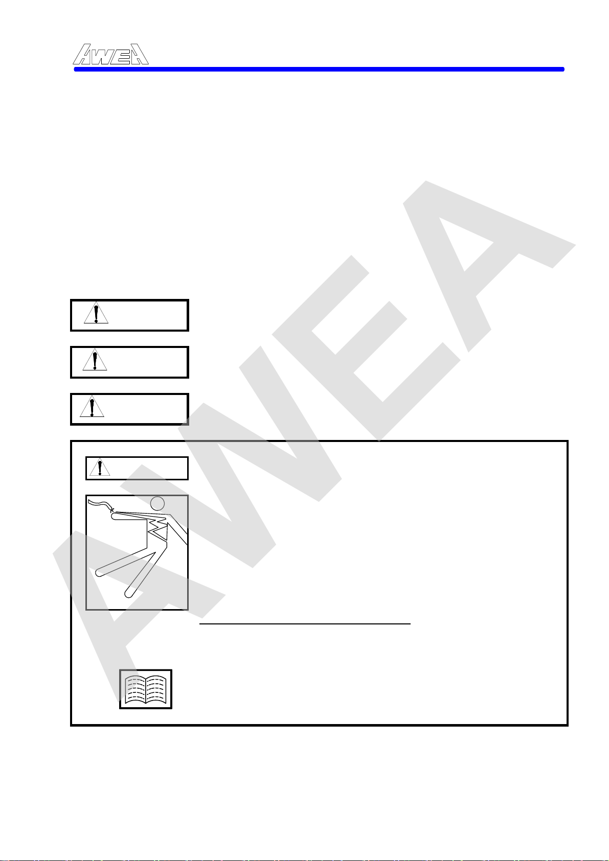
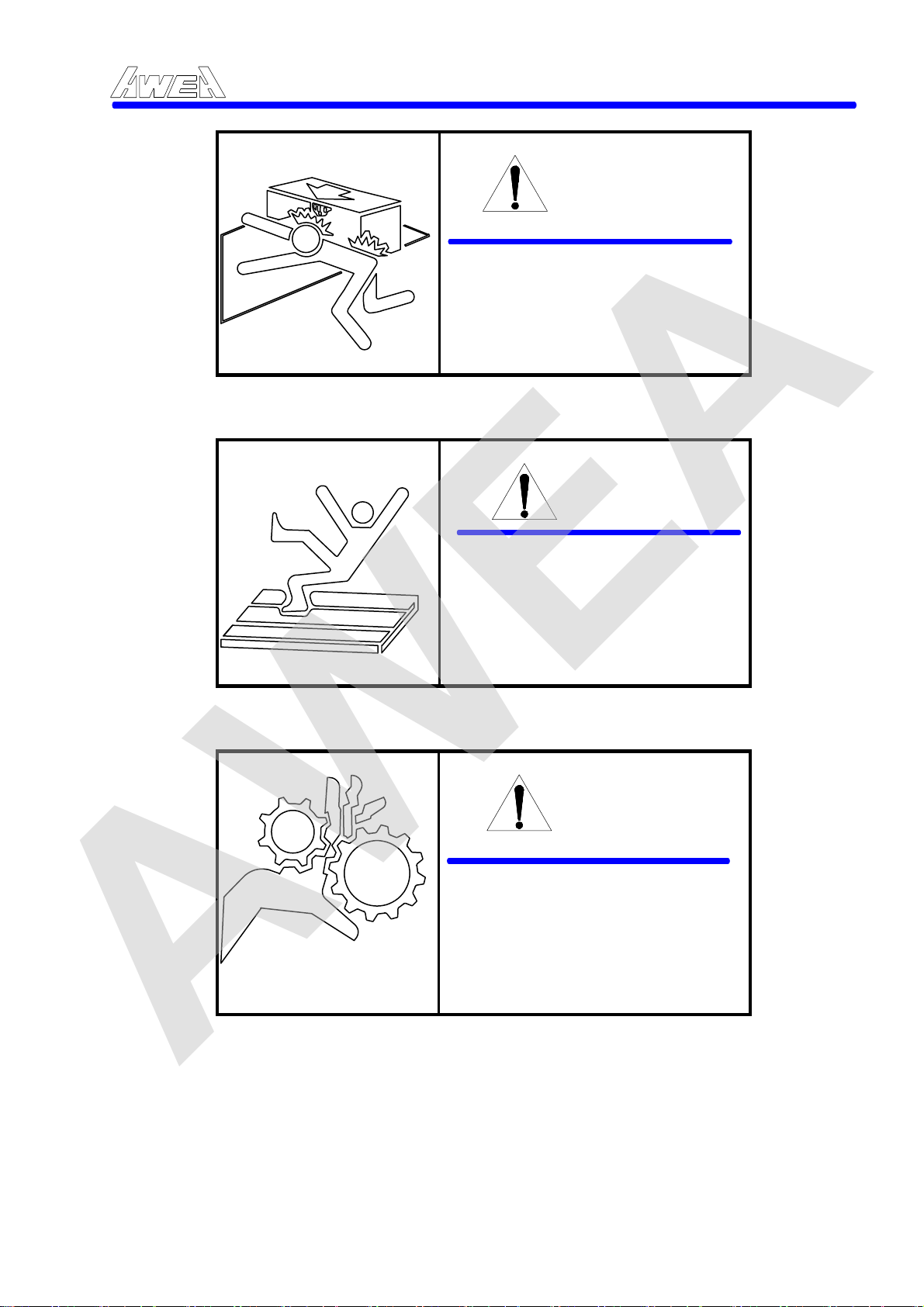
INDICATES FAILURE TO DO SO WILL RESULT IN SERIOUS
DANGER
WARNING
CAUTION
‧Indicates points to be followed.
DANGER
INJURY OR DEATH.
INDICATES FAILURE TO DO SO COULD RESULT IN SERIOUS INJURY OR DEATH.
INDICATES FAILURE TO DO SO MAY RESULT IN SERIOUS INJURY OR DEATH.
Shows to follow safety instructions.
‧(same as above)
‧
‧
1.(Indicates: refer to the points below)
2.________________________________________
3.________________________________________
(Indicates manuals, chapters or sections to
be searched for)
1-1

AWEA
1.1 SAFETY INSTRUCTIONS:
READ COMPLETE INSTRUCTIONS CAREFULLY BEFORE OPERATING MACHINE
When this instruction manual was printed, the information given was current.
However, since we are constantly improving the design of our machine tools, it is
possible that the illustrations and descriptions may vary from the machine you
received. This means that the machine you received is the latest improved model to
better fulfill your requirements.
Your AWEA machine is designed and built for maximum ease and safety of
operation. However, some previously accepted shop practices may not reflect
current safety regulations , environment protection and procedures, and should be
re-examined to insure compliance with the current safety, environment protection,
resources recycling and health standards.
We recommend that all shop supervisors, maintenance personnel, machine and
tool operators be advised of the importance of safety maintenance, environment
protection, setup and operation of AWEA built equipment. Our recommendations
are described below.
PLEASE READ THESE SAFETY RECOMMENDATIONS BEFORE
PROCEEDING ANY FURTHER. (“*” indicated: safety item, “+” indicated
environment protection items)
* ALLOW ONLY AUTHORIZED PERSONNEL to have access to enclosures
containing electrical equipment.
* READ APPROPRIATE MANUAL OR INSTRUCTIONS before attempting
operation or maintenance of machine. Make sure you understand all
instruction.
* CONSULT YOUR SUPERVISOR when in doubt as to the correct way to do a
job.
* DO NOT OPERATE EQUIPMENT unless proper maintenance has been
regularly performed and the equipment is known to be in good wor
* DO NOT OPERATE EQUIPMENT in the possible environment of air explosive.
+ DO NOT CUT THE FLAMMABLE MATERIAL (like Magnesium base) by
operating of the machine to avoid any possibility of fire.
* BEFORE OPERATING THE MACHINE check that all protective components
and interlocks work properly. If not immediately contact your local distributor.
* DO NOT REMOVE ANY WARNING or INSTRUCTION TAGS from machine.
* DO NOT OPERATE MACHINE if unusual or excessive noise or vibration
occurs. Report any excessive or unusual vibration, sounds, smoke, or heat as
well as any damaged parts.
* MAKE SURE MACHINE IS PROPERLY GROUNDED. CONSULT NATIONAL
ELECTRIC CODE and all local code.
* KEEP AREA AROUND MACHINE well light and dry.
* KNOW WHERE ALL stop push buttons are located in case of an emergency.
* DO NOT REACH into any control or power cases area unless electrical power
is OFF.
* DO NOT TOUCH ELECTRICAL EQUIPMENT when hands are wet or when
standing on a wet surface.
AWEA SP/LP Series Manual - Chapter 1. SAFETY RECOMMENDATIONS:1-2
king order.
1-2

AWEA
+ DO NOT USE a toxic or flammable substance as a solvent cleaner or coolant.
* DO NOT ALTER THE MACHINE to bypass any interlock, overload,
dis-connect or other safety device.
* KEEP CHEMICAL AND FLAMMABLE MATERIAL away from electrical or
operating equipment.
* DO NOT OPEN GUARD DOORS while any machine component is in motion.
* MAKE SURE PROPER GUARDING is in place and all doors are closed and
secured.
* MAKE SURE fixture plates and all other spindle-mounted tool holding devices
are properly mounted and secured before starting machine.
* REMOVE ANY LOOSE PARTS OR TOOLS left on machine or in the work area
before operating machine. Always check machine and work area for loose
tools and parts especially after work had been done by maintenance personal.
* CHECK LUBE LEVEL and status of indicator lights before operating machine.
* MAKE CERTAIN that all guards are in good condition and are functioning
properly before operating machine.
* DISCONNECT MAIN ELECTRICAL POWER before attempting repair or
maintenance.
* REPLACE BLOWN FUSES with fuses of the same size and type as originally
furnished.
* ASCERTAIN AND CORRECT cause of a shutdown caused by overload
heaters before starting machine.
* WEAR SAFETY GLASSES AND PROPER FOOT PROTECTION at all times.
When necessary, (example: remove the workpieces from the table, tools from
the spindle, clean the table, replacing the liquid or maintain the equipment)
wear respirator, helmet, gloves and ear muffs or plugs.
* DO NOT WEAR GLOVES if you are operating the control panel or the chip
conveyor
* HAVE CORRECT TYPE OF FIRE EXTINGUISHER handy when machining
combustible material and keep chips clear of working area.
* BEFORE PRESSING CYCLE START PUSH-BUTTON, make
proper functions are programmed and that all controls are set in desired
modes.
* CHECK SETUP, TOOLING AND SECURITY OF WORKPIECE if machine has
been off for any length of time.
* DRY CYCLE a new setup to check for programming errors.
* DO NOT REMOVE CHIPS with hands. Use a hook or similar device and make
certain that all machine movements have ceased.
* BE CAREF
* DO NOT REMOVE OR LOAD workpieces while any part of the machine is in
motion.
* DO NOT CHECK finishes or dimensions of workpiece near running spindle or
moving slides.
* DO NOT ATTEMPT to brake or slow the machine with hands or any makeshift
device.
* USE CAUTION around exposed mechanisms and tooling especially when
setting up. Be careful of sharp edges on tools.
* DO NOT USE worn or defective hand tools. Use proper size and type for job
being performed.
* USE ONLY a soft-faced hammer on tools and fixtures.
* DO NOT USE worn or broken tooling on machine.
AWEA SP/LP Series Manual - Chapter 1. SAFETY RECOMMENDATIONS:1-3
certain that
UL of sharp edges when handling newly machined workpieces.
1-3

AWEA
* MAKE CERTAIN that all tool mount surfaces are clean before mounting tools.
* INSPECT ALL CLAMPING DEVICES daily to make sure they are in good
operating condition. Replace defective clamper before starting machine.
* USE LIGHTER THAN NORMAL feedrate and depth of cut when machining a
workpiece size that is larger than the WORKING CAPACITY.
* DO NOT EXCEED rated capacity of machine.
* DO NOT LEAVE machine unattended while it is operating.
* DO NOT CLEAN machine with an air hose.
* RECYCLING all replaced parts and chips to save the resources.
* MAKE SURE that the waste are well disposed to conform to the environmental
protection regulations. (like wasted oil, coolant etc.)
* DO NOT LEAVE the leaking oil unattended, recycling the leaking oil by
wooden chip.
AWEA SP/LP Series Manual - Chapter 1. SAFETY RECOMMENDATIONS:1-4
1-4
AWEA
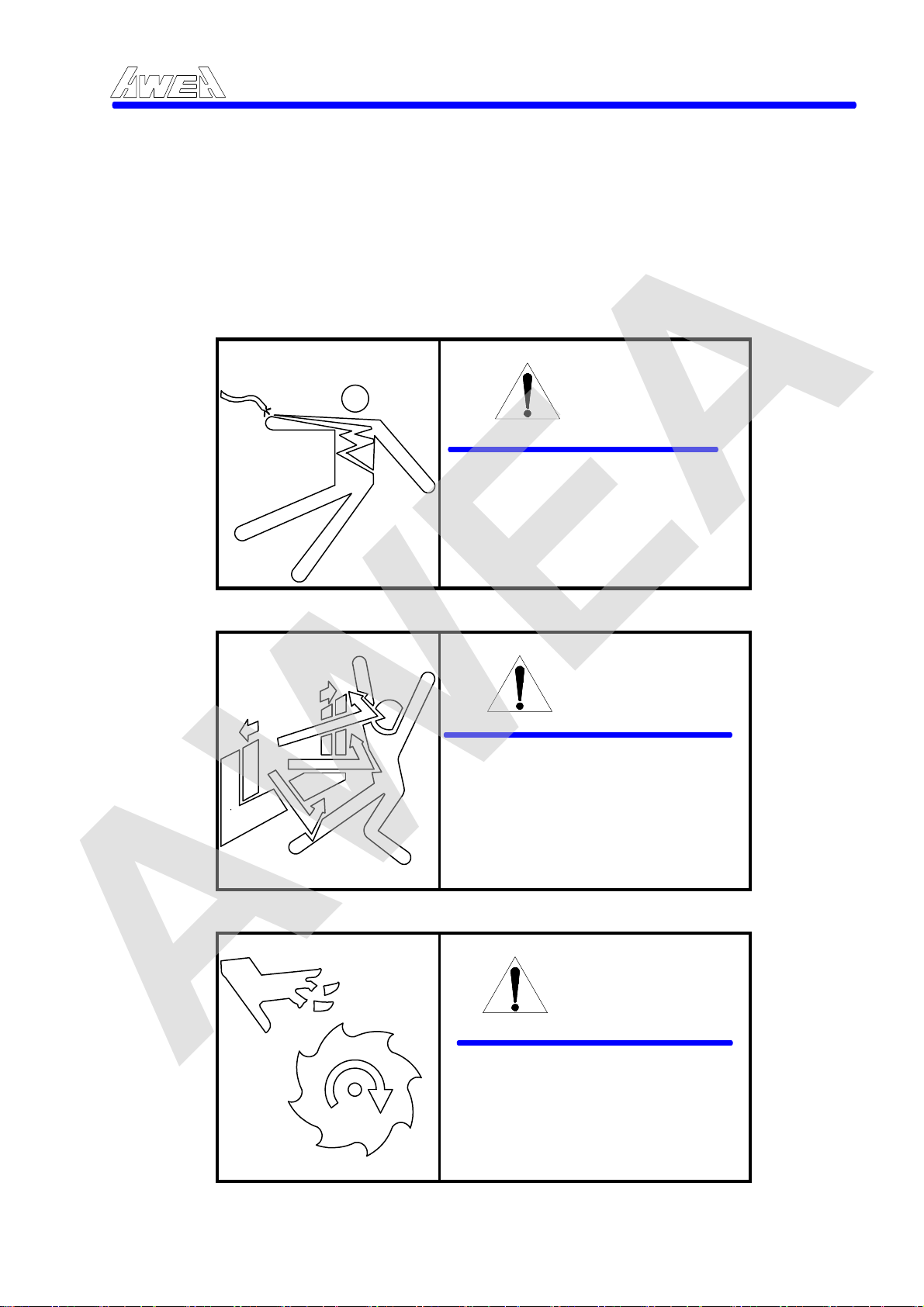
1.2 SAFETY LABELS EXPLANATION
The following warning labels and an instruction plate are attached to the machine.
Read and make sure you understand the warnings before operation. If any label is
damaged or becomes illegible, contact your local distributor. A new one will be
supplied immediately.
NEVER REMOVE OR DISFIGURE ANY WARNING LABEL OR INSTRUCTION PLATE.
AWEA SP/LP Series Manual - Chapter 1. SAFETY RECOMMENDATIONS:1-5
DANGER
ONLY qualified personnel are authorized to service electric cabinet. Failure to do so will result in serious injury or death.
Figure 1-1
WARNING
NEVER open the door during AUTO operation.
Figure 1-2
WARNING
ALWAYS keep away from spindle or tool in motion. Shut power OFF before access to spindle for servicing.
Figure 1-3
1-5
AWEA
AWEA SP/LP Series Manual - Chapter 1. SAFETY RECOMMENDATIONS:1-6
WARNING
KEEP AWAY from movable
area during operation.
Shut machine OFF for
servicing.
Figure 1-4
WARNING
WEAR HELMET and proper
foot protection to setup and
service.
Shut machine OFF when
step in/on machine.
Figure 1-5
WARNING
NEVER open the cover, only qualified person is authorized to service. Shut the machine OFF before servicing.
Figure 1-6
1-6
AWEA
Follow instructions written on labels, Removal and / or damage to labels
is prohibited.
1. BEFORE operation of machine, READ operator's manual and safety
instructions.
2. ONLY trained and qualified personnel are to operate this machine.
3. ALL GUARDS MUST remain in place during machine operation.
4. MANDATORY wearing of hard hat for set-up and service. Clothing
suitable for operation of machine a MUST. (safety shoes, goggles,
protection cap, etc.)
5. Proper use, knowledge and location of EMERGENCY STOP BUTTON is
imperative.
AWEA SP/LP Series Manual - Chapter 1. SAFETY RECOMMENDATIONS:1-7
SAFETY INSTRUCTIONS
6. SHUT OFF POWER before servicing.
7. ONLY TRAINED AND QUALIFIED personnel may service this machine.
8. STAND CLEAR of machine while in operation. KEEP hands free of
movable areas.
9. SECURE ALL tools and workpiece safely. Check that nothing will
interfere with machine motions.
10. ONLY USE WATER-BASE coolant to prevent fire during unmanned
operation.
Failure to follow the above instructions may result in serious personal
y or death. If any questions or doubt exist regarding the instruction or
injur
operation procedures, contact your local distributor.
Figure 1-7 Safety Instruction Plate
1-7
AWEA
2. INSTRUCTION
2.1 Description of machine design and construction
The basic machine consists of the Machine bed, Table, The bridge, Saddle, Spindle
Carrier, Dual hydraulic counter balance system and Auto tool changing system.
(Refer to Figure 2-1). All of which are designed to give high precision for long term
and heavy duty cutting performance over many years of machining operation. All of
which are described as below:
9 10 11 12 13 14 15
AWEA SP/LP Series Manual - Chapter 2. INSTRUCTION 2-1
22
1
2
3
4 5 6
7 8
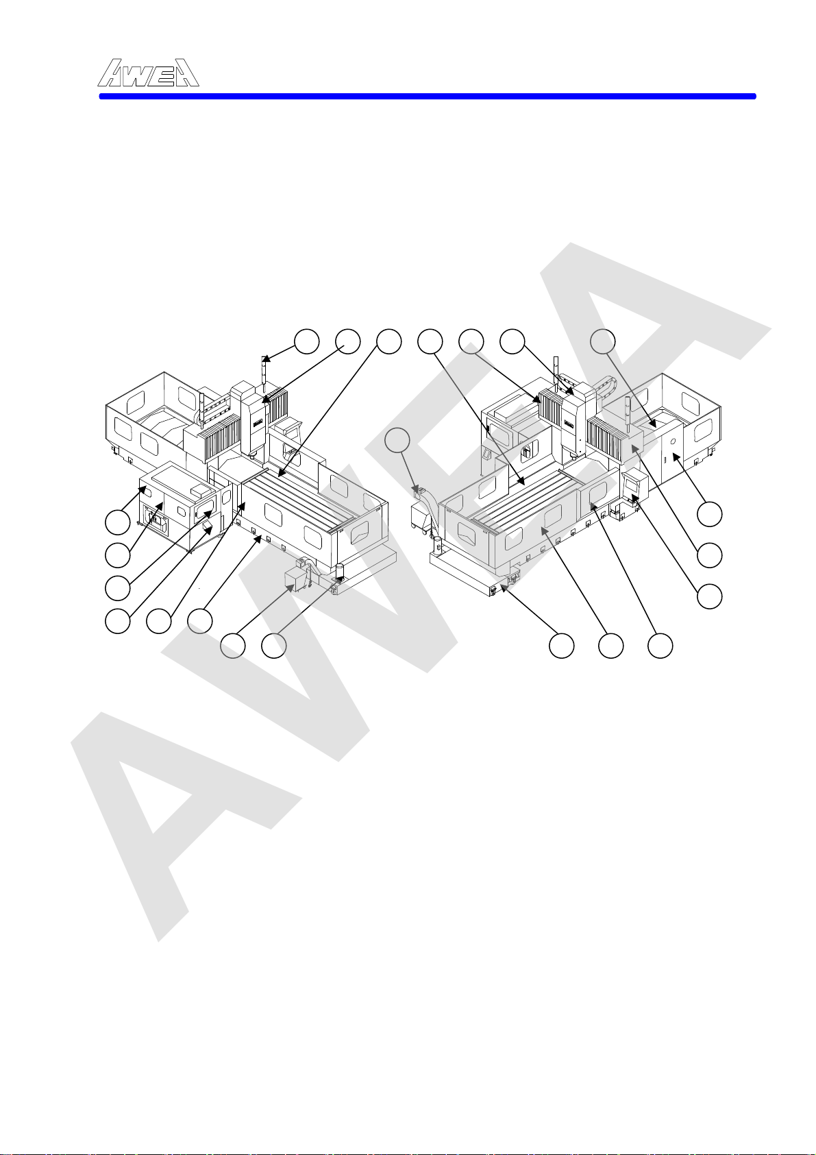
Figure 2-1Over View of SP type Machine layout
The main components of the machine are as below:
1. Tool magazine 12. Chip and coolant through
2. Magazine sheet metal 13. Y axial way cover
3. Magazine operator door 14. Carriage
4. ATC operation panel 15. X axial way telescopic cover
5. ATC automatic door 16. Main electric cabinet
6. Machine bed 17. The Bridge
7. Chip bucket 18. Operator panel
8. Coolant pump 19. Main operator door
9. Finish, alarm & operation lamp 20. Splash guard
10. Spindle head 21. Coolant tank
11. Table
19 20 21
16
17
18
2-1

AWEA
2.1.1 Machine bed
The machine bed is the foundation of the machining center structure. In addition to providing rigidity and support for the sliding members, machine alignment is maintained through the precision leveling of this structure.
2.1.2 The bridge
The bridge is made of one piece, which means columns and beam in one piece.
The thick walls and reinforcement ribs give the machining unsurpassed rigidity and
prevent any bending or twisting that may affect machining accuracy. The bridge is
bolted to the side of the machine bed. The upper linear way bearing is located 75
mm (2.9") behind the lower linear bearing. This step design greatly reduces
headstock overhang for added stability and helps maintain machining accuracy
during heavy cutting operations. The column is bolted to the side of the table base
to ensure the best accuracy alignment and squareness and to allow for maximum
rigidity. The double column construction supports the cutting load symmetrically;
thus bending movement and thermal deflection is minimized.
AWEA SP/LP Series Manual - Chapter 2. INSTRUCTION 2-2
2.1.3 The table
The largest table size not only allows for the machining of large parts but also
increases the productivity of small to medium sized parts as they can be set up and
processed at one time. The wide distance between the columns all allows for extra
clearance for larger work pieces.
2.1.4 The spindle head
The large front bearing to assure efficient power transmission to the spindle nose
and to enable heavy duty machining supports the spindle. For rigidity, a
square-shaped cross section headstock was designed. In addition, with only 90 mm
from the spindle centerline to Z axis, so rigidity is unsurpassed. A floating hydraulic
cylinder keeps the spindle bearing from being pushed during tool change cycle.
This assured long term machine accuracy and spindle life. The counter-balance
system for the headstock consists of two hydraulic cylinders, which are arranged to
perfectly balance the distribution of the weight of the headstock. The twin hydraulic
cylinders are symmetrically placed to ensure equal lading to the way area and to
maintain sensitivity and accuracy to the cutting area.
The spindle temperature is kept constant by use of oil recirculating heat exchanger,
which reduces heat generation. Harmonized temperature between spindle head
and machine body assures minimum spindle expansion at high speeds rotation in
long time continuous use.
2-2

AWEA
2.1.5 The feed system
A custom designed safety device is used on all feed systems to protect the machine
from damage caused by accidental, incorrect programming or accidental operator
error. If tool head interference occurs, a unique torque limiter clutch protects the
machine from major damage. Operations are then restored quickly and easily with
a simple manual realignment of the clutch. Use of low friction linear bearing (X and
Y axes) and Turcite B (Z axis) which has outstanding vibration dampening
characteristics, This allows for high efficiency, high stability, high accuracy for long
term machining and machine life.
The guide ways and ball screw are automatically lubricated. The lubricant is
collected in a reservoir. So that the area keep clean and also extends the life of the
coolant. The entire guide way is fully covered by telescopic covers and coolant
recovery is ensured. Build-in spiral chip conveyor and flood coolant flushing
minimized cleaning time.
2.1.6 The ATC and Magazine
AWEA SP/LP Series Manual - Chapter 2. INSTRUCTION 2-3
Unique ATC assures safe and easy tool storage and construction assures
interference free work setting and trouble-free operation. A standard magazine can
store 32 tools (60 option) of maximum size Φ125 mm X 350 mm ( Φ50" X 13.8")
and weight 20 kg (44 LB) ATC time, tool to tool : 8 seconds. Tools are always
protected from coolant, chips and dust by the automatic tool magazine door. The
door is automatically opened and closed by program command when changing
tools.
Especially design lock pin mechanisms are used to prevent the gripper failure while the arm is rotating. A unique hydra-pneumatic cylinder is used to limit the transfer force, which prevents damage if any malfunction occurs.
Microcomputer controlled random pot coding assures tool selection from magazine
in the shortest bi-direction tool path. The control p
the front side of the cabinet along with the foot release switch. The operator can
manually exchange tools with ease.
anel for the tool magazine is at
2-3
AWEA
2.2 Coordination
Machining centers use the right-hand co-ordinate system to describe the
relationship of the axes. This relationship is in accordance with E.I.A. RS-267-A and
I.S.O. R841 Axis and Motion Nomenclature. The right-hand co-ordinate system
also establishes the direction of cutter motion with respect to the workpiece. The
programming exercise depends on the programmer visualizing the workpiece to be
fixed, and that the cutter does all the moving, (theoretical cutter motion). It is also
essential that the programmer view the workpiece from the normal operator
position, looking through the tool from the machine spindle. A theoretical cutter
motions to the back of current position in the Y axis origin which is created by a
similar movement of the table to the front of current position.
AWEA SP/LP Series Manual - Chapter 2. INSTRUCTION 2-4
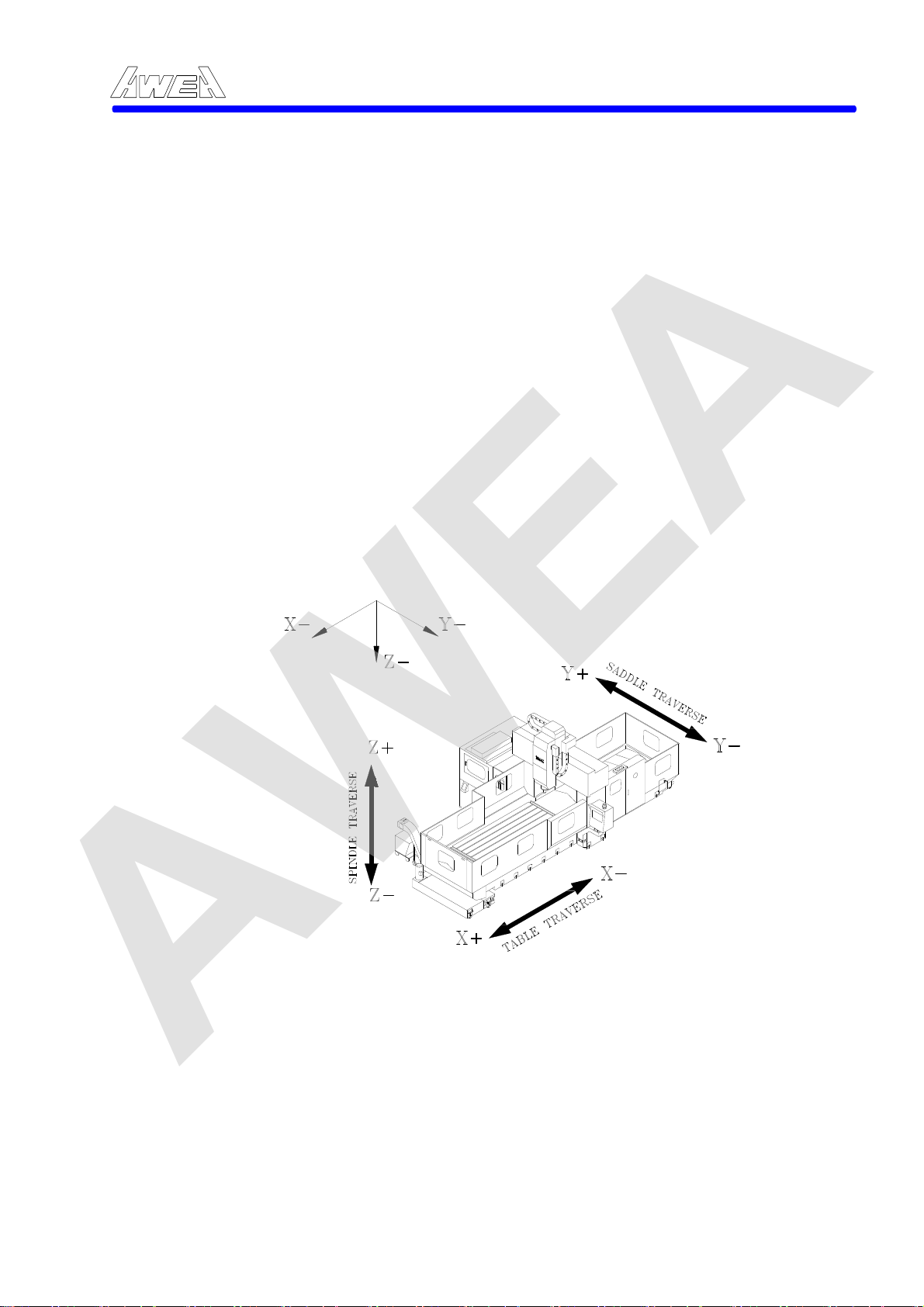
X axis:
Y axis:
Z axis:
Table travel left in "+" direction and travel right in "-" direction.
Spindle head travel out in "+" direction (approach to the Magazine) and travel in in "-" direction (leave from the Magazine).
Spindle carrier travel up in "+" direction and travel down in "-" direction.
Figure 2-2 Machine Axis Orientation
2-4
AWEA
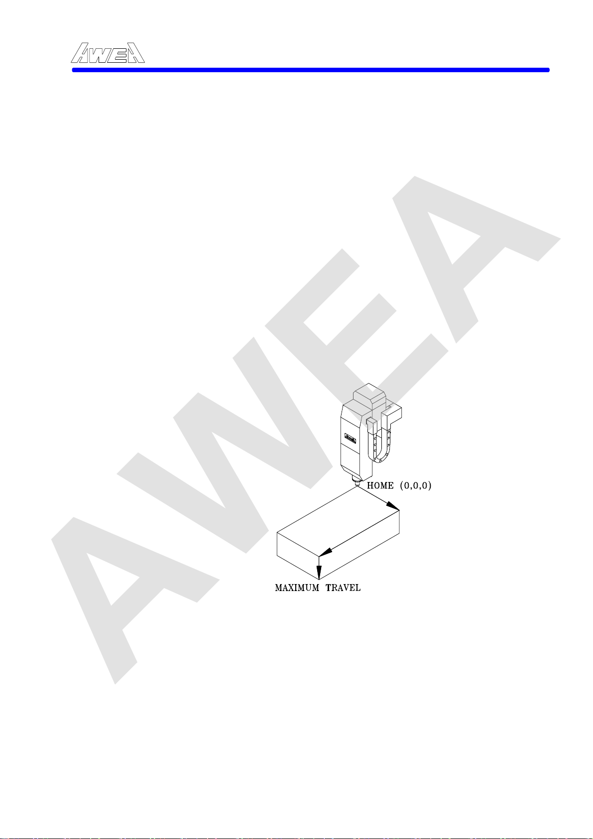
When the origin Point of this co-ordinate system agree with the mechanical 0-0-0
reference point of the machine, all coordinate dimensions will be as mentioned
above drawing, (from center of spindle) The maximum of all axial stroke shown as
mentioned below:
Axis and Machine model SP2016 SP3016 SP4016
X axis 2100(82.7") 3000(120.5") 4000(157.5") Y axis 1600(63") 1600(63") 1600(63") Z axis 760(30") 760(30") 760(30")
Axis and Machine model LP3021 LP4021 LP5021
X axis 3000(118.1") 4000(157.5") 5000(196.8") Y axis 2100(82.6") 2100(82.6") 2100(82.6") Z axis 760(30") 760(30") 760(30")
Axis and Machine model LP3025 LP4025 LP5025 LP6025
X axis 3000(118.1") 4000(157.5") 5000(196.8") 6000(236.2) Y axis 2500(98.4") 2500(98.4") 2500(98.4") 2500(98.4") Z axis 760(30") 760(30") 760(30") 760(30")
AWEA SP/LP Series Manual - Chapter 2. INSTRUCTION 2-5
Figure 2-3 Maximum Travel Limit
2-5

AWEA
2.3 Specifications
2.3.1 Technical Data
AWEA SP/LP Series Manual - Chapter 2. INSTRUCTION 2-6
Item unit
X axis travel mm (inch) 2100 (82.7) 3060 (120.5) 4000 (157.5) Y axis travel mm (inch) 1600 (63.0) Z axis travel mm (inch) 760 (30.0) Distance from spindle to table mm (inch) 240-1000 (9.4-39.4) Distance between columns mm (inch) 1700 (66.9) Table size in X direction mm (inch) 2310 (90.9) 3260 (128.3) 4200 (165.4) Table size in Y direction mm (inch) 1500 (59.0) Table load capacity kg (lb.) 8000 (17600) 10000 (22000) 12000 (26400) Spindle motor (cont./30 min) kW (HP) 22/26 (30/35) Spindle speed rpm Two steps geared spindle 10-6000 Spindle taper BT#50 (ISO50) Pull-stud MAS403P50T-1 (45Deg.) / DIN69782 Rapid traverse rate X axes mm(in)/min. 20,000 (787.4) 20,000 (787.4) 15,000 (590.6) Rapid traverse rate Y axes mm(in)/min. 20,000 (787.4) Rapid traverse rate Z axis mm(in)/min. 10,000 (393.7) Cutting feed rate (max.) mm(in)/min. 1 – 1,0000 (0.04 – 393.7) Tool magazine capacity Max. tool diameter/ adjacent
pocket empty Max. tool length mm (in) 350 (13.8) Max. tool weight kg (lb.) 20 (44.1) Tool change time (T to T) sec 8 Position accuracy (JIS B6338) mm (in) ±0.01 (0.004) / full travel Position accuracy (VDI 3441) mm (in) P=0.030 (0.0012) Repeatability (JIS B6338) mm (in) ±0.003 (0.0001) Repeatability (VDI 3441) mm (in) Ps=0.024(0.001) Total required power 60 KVA / AC220V ±10%, 3 Phase, 60 Hz/50Hz Air resource Hydraulic tank capacity liter (gallon) 120 with 10HP (31.8)
Lubrication oil tank capacity
Coolant tank capacity liter (gallon) 420 (110) at 1.5HP Floor space requirement, L mm (in) 6,690 (263.3) 8,680 (341.7) 10,680 (420.5)
Floor space requirement, WxH mm (in)
Machine weight kg (lb.) 23,000(50700) 27,000(59500) 30,000 (66100) CNC controller FANUC 18 iMB FANUC 18 iMB FANUC 18 iMB
mm (in)
kg/c㎡
Liter
(gallon)
SP2016 SP3016 SP4016
32 (60,120 Option)
127/215 (5.0/8.5)
5
6 (1.6)
4700 x 3980
(185 x 156.7)0
2-6

AWEA
Item
X axis travel mm (inch) 3000 (118.1) 4000 (157.5) 5000 (196.8) Y axis travel mm (inch) 2100 (82.6) Z axis travel mm (inch) 760 (30.0) Distance from spindle to table mm (inch) 240-1000 (9.4-39.4) Distance between columns mm (inch) 2300 (90.5) Table size in X direction mm (inch) 3020 (118.9) 4020 (158.3) 5020 (197.6) Table size in Y direction mm (inch) 2010 (79.1) Table load capacity kg (lb.) 10000 (22000) 12000 (26450) 15000 (33000) Spindle motor (cont./30 min) kW (HP) 22/26 (30/35) Spindle speed rpm Two steps geared spindle 10-6000 Spindle nose configuration BT#50 (ISO50) DIN69871A Pull-stud MAS403P50T-1 (45Deg.) / DIN69782 Rapid traverse rate X axes mm(in)/min. 15,000 (590.0) 15,000 (590.0) 10,000 (393.7) Rapid traverse rate Y axes mm(in)/min. 15,000 (590.0) Rapid traverse rate Z axis mm(in)/min. 10,000 (394)
Cutting feedrate (max.) mm(in)/min.
Tool magazine capacity 32 (60 , 120 Option) Max. tool diameter/ adjacent
pocket empty Max. tool length mm (in) 350 (13.8) Max. tool weight kg (lb.) 20 (44.1) Tool change time (T to T) sec 8 Position accuracy (JIS B6338) mm (in) ±0.015 (0.006) / full travel Position accuracy (VDI 3441) mm (in) P=0.035 (0.0014) Repeatability (JIS B6338) mm (in) ±0.003 (0.0001) Repeatability (VDI 3441) mm (in) Ps=0.028(0.001) Total required power KVA 60 70 70 220 ±10% Vac, 3 Phase, 60 / 50Hz Air resource Hydraulic tank capacity liter (gallon) 120 with 10HP (31.8)
Lubrication oil tank capacity
Coolant tank capacity liter (gallon) 650 (170) at 1.5HP Floor space requirement, L mm (in) 8580 (337.8) 10580 (416.5) 12680 (499.2)
Floor space requirement, WxH mm (in)
Machine weight kg (lb.) 33000 (72750) 38000 (83700) 45000 (99200) CNC controller FANUC 18 iMB FANUC 18 iMB FANUC 18 iMB
mm (in)
kg/c㎡
Liter
(gallon)
AWEA SP/LP Series Manual - Chapter 2. INSTRUCTION 2-7
unit LP3021 LP4021 LP5021
1 - 10000
(0.04-393.7)
127/215 (5.0/8.5)
5
6 (1.6)
5240 x 4000
(206.3 x 157.5)
5240 x 4000
(206.3 x 157.5)
5240 x 4000
(206.3 x 157.5)
2-7

AWEA
Item unit LP3025 LP4025 LP5025 LP6025 X axis travel Y axis travel Z axis travel
Distance from spindle to table
Distance between columns
Table size in X direction
Table size in Y direction
Table load capacity
Spindle motor (cont./30 min)
Spindle speed
Spindle nose configuration
Pull-stud MAS403P50T-1 (45Deg.) / DIN69782
Rapid traverse rate X axes
Rapid traverse rate Y axes
Rapid traverse rate Z axis
Cutting feed rate (max.)
Tool magazine capacity
Max. tool diameter/ adjacent pocket empty
Max. tool length
Max. tool weight
Tool change time (T to T)
Position accuracy (JIS B6338)
Position accuracy (VDI
3441)
Repeatability (JIS B6338)
Repeatability (VDI 3441)
Total required power KVA 60 70 70 80 220 ±10% Vac, 3 Phase, 60 Hz / 50Hz Air resource
Hydraulic tank capacity
Lubrication oil tank capacity
Coolant tank capacity
Floor space requirement, L
Floor space requirement, WxH
Machine weight
CNC controller
mm (inch) 3000 (118.1) 4000 (157.5) 5000 (196.8) 6000 (236.2)
mm (inch) 2500 (98.4)
mm (inch) 760 (30.0)
mm (inch) 240-1000 (9.4-39.4)
mm (inch) 2700 (106.3)
mm (inch)
mm (inch) 2400 (94.5)
kg (lb.) 12000 (26400) 15000 (33000) 18000 (39680) 20000 (44000)
kW (HP) 22/26 (30/35)
rpm Two steps geared spindle 10-6000
mm(in)/min.
mm(in)/min.
mm(in)/min.
mm(in)/
min.
mm (in)
mm (in) 350 (13.8)
kg (lb.) 20 (44.1)
sec 8
mm (in) ±0.015 (0.006) / full travel
mm (in)
mm (in) ±0.003 (0.0001)
mm (in)
kg/c㎡
Liter
(gallon)
Liter
(gallon)
liter
(gallon)
mm (in) 8600 (338.5) 10600 (417.3) 12600 (496) 14600 (574.8)
mm (in)
kg (lb.)
AWEA SP/LP Series Manual - Chapter 2. INSTRUCTION 2-8
3020 (118.9) 4020 (158.3) 5020 (197.6)
BT#50 (ISO50) DIN69871A
15,000 (590.0)
1-10000
(0.04-393.7)
P=0.035
(0.0014)
Ps=0.028
(0.0011)
5630 x 4000
(221.7 x 157.5)
36000 (79400) 40000 (88100) 44000 (97000)
FANUC 18 iMB FANUC 18 iMB FANUC 18 iMB FANUC 18 iMB
2-8
10,000 (393.7)
15,000 (590.0) 10,000 (393.7)
1-10000
(0.04-393.7)
32 (60 , 120 Option)
127/215(5.0 / 8.5)
P=0.035
(0.0014)
Ps=0.028
(0.0011)
120 with 10HP (31.8)
6 (1.6)
750 (198) at 1.5HP
5630 x 4000
(221.7 x 157.5)
10,000 (393.7)
1-10000
(0.04-393.7)
P=0.045
(0.0018)
Ps=0.028
(0.0011)
5
5630 x 4000
(221.7 x 157.5)
6020 (237)
7500 (295.3)
1-5000
(0.04-196.9)
P=0.055
(0.002)
Ps=0.045
(0.0018)
5630 x 4000
(221.7 x 157.5)
48000
(105800)

AWEA
A. Standard Accessories :
1. Spindle temperature control system
2. Spindle lubricating monitoring system
3. Two step gear head
4. Adjustable torque-limiting overload clutch (3 axes).
5. External pulse coder installed on end of ball screw, 3axes
6. Centralized automatic lubricating system
7. Flood coolant system
8. Recycling lubricating oil collector for all axes
9. Full splash guard - 1700 mm (66.9")
10. Foot switch for tool clamping (operator and magazine sides).
11. Remote hand wheel control.
12. Work light.
13. Operation cycle finish and alarm lights.
14. RS-232 interface.
15. Foundation bolt kit.
16. Tool box
17. Operation and maintenance manual
B. Optional accessories.
1. Rigid tapping
2. 8000 rpm spindle (30/35 HP, direct driven)
3. Linear scale feedback system for X, Y axes.
4. 60 tools magazine.
5. Angular head indexing in 4 position (Max. speed up to 1500 rpm)
6. Dual screw type chip conveyor
7. Caterpillar type chip conveyor and chip bucket
8. Automatic tool length measurement
9. Automatic workpieces measuring system (Renishaw MP10)
10. 10. Scanning system for mold and die.
11. CNC rotary table
12. Coolant thru the tool adaptor
13. Coolant thru the spindle with filtering system (Form 1 or 2).
AWEA SP/LP Series Manual - Chapter 2. INSTRUCTION 2-9
2-9

AWEA
2.3.2 Control function (Standard)
01. Controlled axes 3 Axes 3 Axes
02. Simultaneous controllable axes 3 Axes 3 Axes
03. Least input increment
04. G20 Inch/ G21 metric conversion
05. Interlock
06. Machine lock
07. Emergency stop
08. Stored stroke check
09. Backlash compensation
10. Stored pitch error compensation
11. Automatic operation (memory)
12. DNC operation
13. MDI operation
14. Program number search
15. Sequence number search
16. Dry run
17. Single block
18. JOG feed
19. Manual reference position return
20. Manual handle feed
21. Incremental feed
22. G00 Positioning (G01 type positioning is possible)
23. G61 Exact stop mode
24. G09 Exact stop
25. G01 Linear interpolation
26. G02, G03 Circular interpolation
27. Dwell
28. G31 Skip function
29. G28 Reference position return
30. G27 Reference position return check
31. 2nd reference position return
32. Rapid traverse rate
33. Rapid traverse override Fo,25,50,100%
34. Automatic acceleration/deceleration (Rapid traverse:linear, Cutting feed:exponential)
35. Feedrate override
36. Override cancel
37. EIA/ISO Automatic recognition
38. Label skip
39. Optional block skip
40. Program number O4-digit
41. Sequence number N5-digit
42. G90 Absolute/G91 incremental programming
43. Decimal point input
44. Pocket calculator type decimal point input
AWEA SP/LP Series Manual - Chapter 2. INSTRUCTION 2-10
:
.001mm/0.00001inch
x1,x10,x100
2-10

AWEA
45. Plane selection G17,G18,G19
46. Coordinate system setting
47. Automatic coordinate system setting
48. Workpiece coordinate system
49. Manual absolute on/off
50. Rigid tapping
51. Sub program call: 4 folds nested
52. Custom macro B
53. Canned cycles for drilling
54. Circular interploation by R programming
55. Miscellaneous function
56. Miscellaneous function lock
57. S code
58. Spindle speed override
59. Spindle orientation
60. T code
61. Tool offset memory
62. Tool length compensation
63. Cutter cpmpensation C
64. Part program storage length
65. Registered programs
66. Part program editing
67. Program protect signal
68. Status display
69. Clock function
70. Current position display
71. Program display (Program name 31 characters)
72. Parameter setting and display
73. Self-diagnosis function
74. Alarm display
75. Alarm history display
76. Tool offset
77. Help function
78. Run hour and parts count display
79. Actual cutting feedrate display
80. Servo setting screen
81. English display
82. Data protection key 3 types
83. Erase CRT screen display
84.
85. Chinese/English display
86. RS232-C interface
87. Input power supply 220 Vac ±10%
88.
89. Mirror image
90. Program restart
Setting and display unit 10.4" color LCD/MDI
(standard size)
AWEA SP/LP Series Manual - Chapter 2. INSTRUCTION 2-11
G52、G53、G54~G59
:
99 sets
:
160 Meter
:
63
50~60Hz±3Hz
2-11

AWEA
91. Manual handle interruption
92. Single direction positioning
93. Programmable data input
94. 2D coordinate rotation
95. Manual guide
96. Background editing
97. Playback
98. Scaling
AWEA SP/LP Series Manual - Chapter 2. INSTRUCTION 2-12
2-12
3、So
AWEA
2.4 Operator’s Control Panel
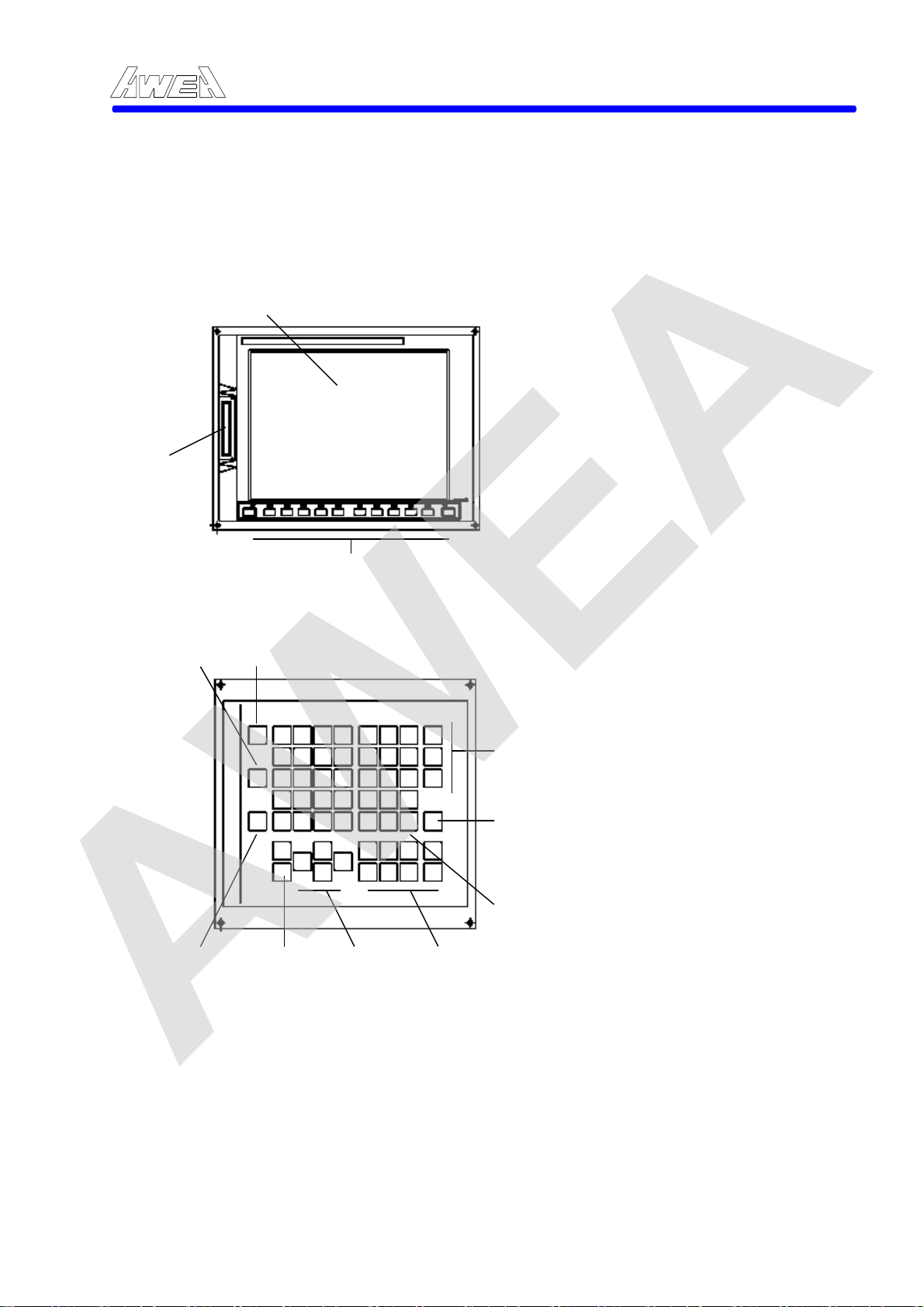
2.4.1 LCD/MDI panel
LCD/MDI consisted of LCD (10.4” color display) and keyboard, shown as Figure 2-4.
【LCD unit】
1、Liquid-crystal display
AWEA SP/LP Series Manual - Chapter 2. INSTRUCTION 2-13
1、10.4 LCD 2、Memory card interface
2、Memory card interface
【MDI unit】
4、Help key
5、Reset key
ft key switch
6、Edit key
7、Cancel key
8、Input key
3、Soft key switch
4、Help key
5、Reset key
6、Edit key
7、Cancel key
8、Input key
9、Function keys
10、Cursor keys
11、Page-Up/Down keys
、Shift key
12
12、Shift key
11、Page-Up/Down keys
10、Cursor keys
Figure 2-4 LCD/MDI panel
9、Function keys
2-13
AWEA
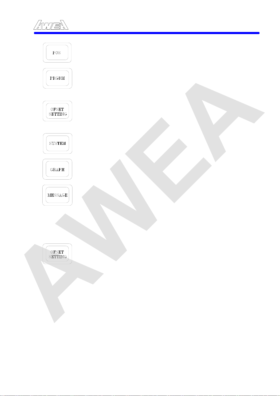
A. Key function:
The position push-button indicates the current position of the slides. The information is spread over pages.
In "EDIT" mode the cursor can be moved the any desired command by
using the Cursor Forward or Reverse.
In "MDI" mode the cursor can be input data to the buffer memory.
In "AUTO" mode the cursor can be displayed current commends.
The OFFSET push-button displays either the offset chapter or work shift chapter. Repeatedly pressing "OFFSET" push-button will alternately display on chapter or the other.
The button displays setting of the System Diagnostic data and System parameter data.
The button displays Alarm messages of interest to the operator in two chapter.
The software operator's manual shown as following figure which can be determined by the following procedure:
1. Press the Offset & Setting button.
AWEA SP/LP Series Manual - Chapter 2. INSTRUCTION 2-14
Î
OPR 3. Select the OPR soft
2. Select the manual by pressing this button which located under the CRT
-key by pressing the button located under the CRT
4. Press the page button down, then the following picture will be displayed.
2-14
 Loading...