

Page 1

Control Tool Quick
Start Guide
Page 2
Table of Contents
Overview ......................................................................................................................................................................... 1
Requirement .................................................................................................................................................................. 1
Scope .......................................................................................................................................................................... 1
Hardware Information ....................................................................................................................................................... 1
Evaluation Board ............................................................................................................................................................. 1
Passive Evaluation Board .............................................................................................................................................. 1
Active Evaluation Board ................................................................................................................................................ 2
USB UART Cable ............................................................................................................................................................. 3
Computer with Windows OS ............................................................................................................................................... 4
Connection .................................................................................................................................................................... 4
Passive Evaluation Board Connection ............................................................................................................................... 4
Active Evaluation Board Connection ................................................................................................................................. 5
Software Information ........................................................................................................................................................ 5
Installation ...................................................................................................................................................................... 5
Installing the Driver.......................................................................................................................................................... 5
Installing the Ethertronics Control Tool .................................................................................................................................. 6
Quick Start Guide ............................................................................................................................................................. 7
Ethertronics control Tool ................................................................................................................................................... 7
Conguration Tab ....................................................................................................................................................... 8
Auto Demo Tab .......................................................................................................................................................... 8
Manual Demo Tab ....................................................................................................................................................... 9
Link Quality Tab .......................................................................................................................................................... 9
Link Information Tab .................................................................................................................................................. 10
LoRa Network Tab ..................................................................................................................................................... 10
AT Commands Tab .................................................................................................................................................... 11
Tera Term ................................................................................................................................................................... 11
Page 3
Application Note 006
Control Tool Quick Start Guide
OVERVIEW
The purpose of this document is to explain the quick steps communicate with module EtherLoRa ETH-LORA-M-AX-01 (V1.2) via UART interface. In order to that,
Ethertronics has developed evaluation boards for this module.
Two types of evaluation boards have been designed to test the features of the ETH-LORA-M-AX-01 (V1.2), Evaluation Board Active and Passive.
This document is divided in four main parts:
Hardware information
Software information
Installation
Quick Start Guide
REQUIREMENT
To follow the procedures in this document the items below are needed.
Hardware Tools:
1. EtherLoRa module ETH-LORA-M-AX-01 (V1.2) Evaluation board (Passive and/or Active)
2. USB-UART Cable (FTDI USB-UART TTL Cable)
3. Computer with windows OS
Software Tools:
1. Driver for USB-UART cable
2. Ethertronics Control Tool
3. Tera Term (optional)
SCOPE
This document focuses on quick start guide on how to communicate with the module ETH-LORA-M-AX independently of the functionality of the module.
HARDWARE INFORMATION
EVALUATION BOARD
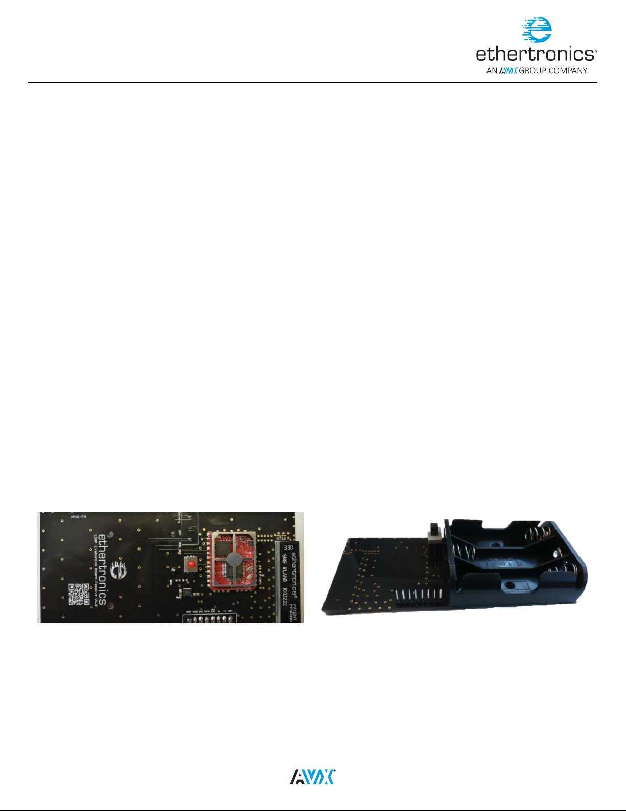
To facilitate the nal product’s developers, Ethertronics has built completed passive and active evaluation boards (EVBs) for ETH-LORA-M-AX-01 (V1.2). In order
to test the functionalities of the IM algorithm, a passive evaluation board is used and to test the functionalities of the MCD algorithm, an active evaluation board
is used. This evaluation boards come with test connectors to communicate with ETH-LORA-M-AX-01 using AT commands via UART interface.
PASSIVE EVALUATION BOARD
This passive evaluation is also provided with Ethertronics’ PresttaTM 1002232 Multi-Band ISM antenna which covers all the ISM frequencies
(868/915/2400 MHz).
PASSIVE EVB (BOTTOM VIEW)PASSIVE EVB (TOP VIEW)
Figure 1
Figure 2
09 2419
1
Page 4
Application Note 006
Control Tool Quick Start Guide
EVB PASSIVE COMPONENTS
Component Position Function Description
ETH-LORA-M-AX-01 Top LoRa Module Module to communicate LoRa communication
PresttaTM 1002232 Top Passive Antenna Emit/receive the signal
Push Button Top Reset button Reset the ETH-LORA-M-AX-01
Test connectors Bottom UART/Power Supply To communicate using AT Commands and to supply the voltage to the module
Toggle switch Bottom Power Supply selection To select the power supply whether from Battery or Test connector
Battery holder Bottom Place for 3 AA batteries To supply the voltage to the module
Table 1
For more information about the passive evaluation board, please refer to LoRa_Module_Application_Note_1-Passive Evaluation Board document from
www.avx.com/products/modules/lora-module.
ACTIVE EVALUATION BOARD
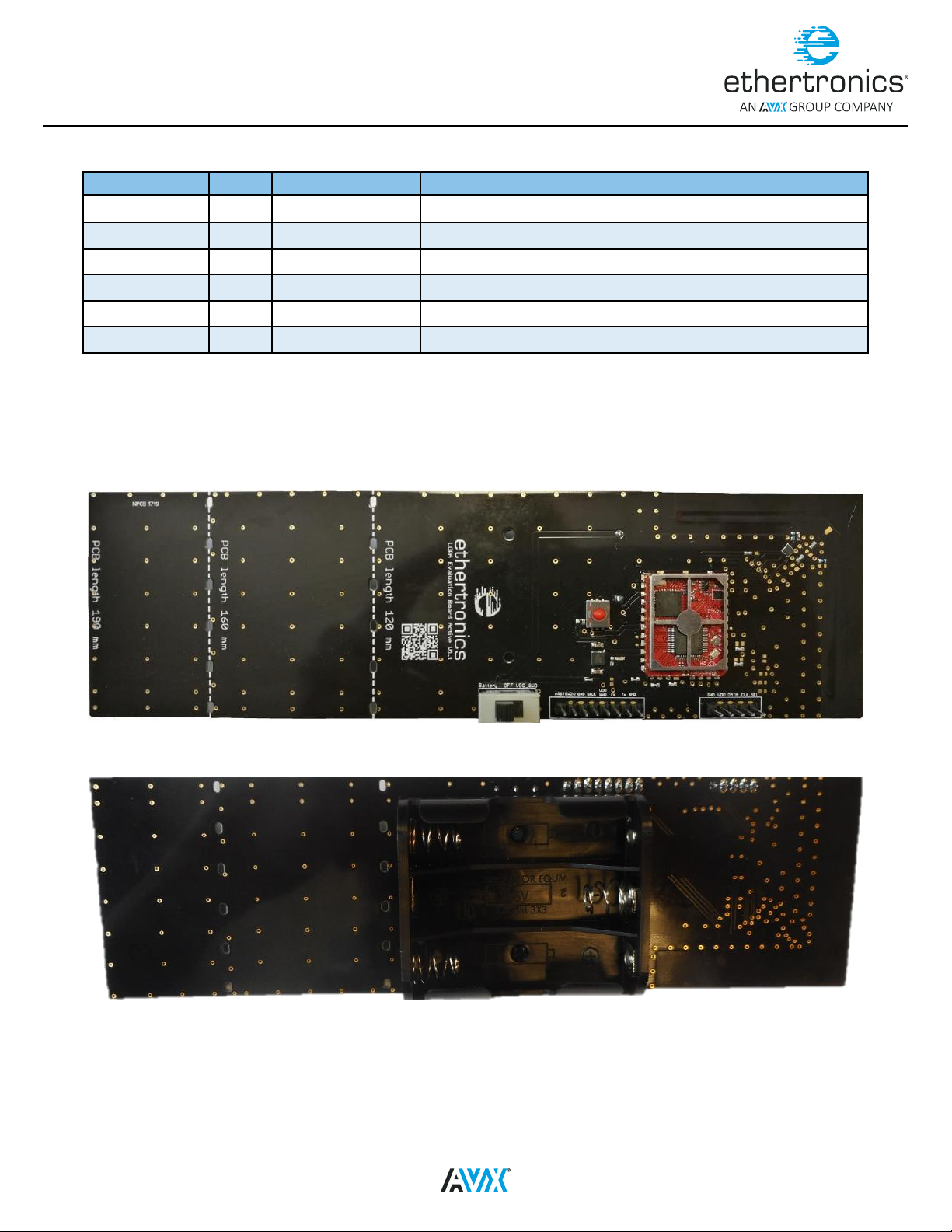
This board is also provided with Ethertronics’ Active Steering antenna for ISM Band which covers the LoRa frequencies (868/915 MHz).
ACTIVE EVB (TOP VIEW)
ACTIVE EVB (TOP VIEW)
Figure 3
Figure 4
2
09 2419
Page 5
Application Note 006
Control Tool Quick Start Guide
ACTIVE EVB COMPONENTS
Component Position Function Description
ETH-LORA-M-AX-01 To p LoRa Module Module to communicate LoRa communication
Active Steering PCB Antenna Top Active Antenna with EC686 Emit/receive the signal
Push Button Top Reset button Reset the ETH-LORA-M-AX-01
Test connectors 1 Top UART/Power Supply To communicate using AT Commands and to supply the voltage to the module
Test connectors 2 Top EC686 MIPI interface To communicate directly with the external EC686 via MIPI interface
Tog g le swit ch Top Power Supply selection To select the power supply whether from Battery or Test connector
Battery holder Bottom Place for 3 AA batteries To supply the voltage to the module
Table 2
For more information about the active evaluation board, please refer to LoRa_Module_Application_Note_4-Active Steering Evaluation Board document from
www.avx.com/products/modules/lora-module.
USB UART CABLE
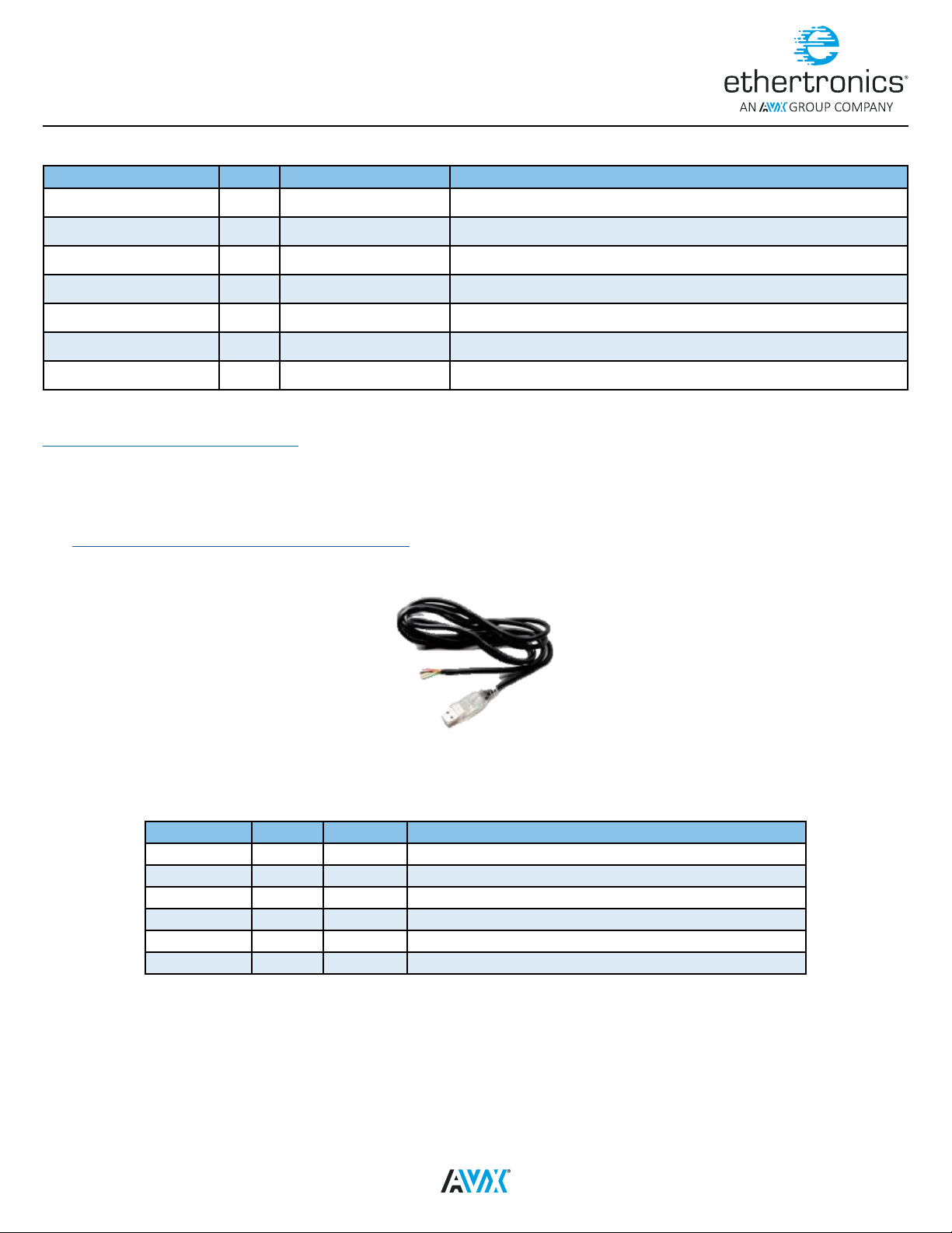
The communication between the host and the module is done using UART interface and AT Commands. To send the data to ETH-LORA-M-AX-01 module, the
USB to TTL serial UART converter cable with virtual COM port driver is necessary. FTDI TTL-232RG-VSW3V3-WE or TTL-232RG-VREG3V3-WE is recommended
for this purpose. The datasheet of this product can be found the FTDI website.
Link: http://www.ftdichip.com/Products/Cables/USBTTLSerial.htm
FTDI USB TTL UART CABLES
Figure 5
Since this cable is wire ended, user needs to make the connectors to connect with the EtherLoRa module pins.
FTDI GENERIC CABLES SIGNAL DESCRIPTIONS
Color Name Type Description
Black GND GND Device ground supply pin.
Brown CTS Input Clear to Send Control input / Handshake signal.
Red VCC Output Power Supply Output
Orange TXD Output Transmit Asynchronous Data output.
Yellow RXD Input Receive Asynchronous Data input.
Green RTS Output Request To Send Control Output / Handshake signal.
Table 3
09 2419
3
Page 6
Application Note 006
Control Tool Quick Start Guide
COMPUTER WITH WINDOWS OS
The software tool is developed to be used on the computer that runs on windows operating system. To communicate with module using other operating
system, user can use serial port terminal.
CONNECTION
The connection of the four pins between the FTDI USB-UART cable and the EtherLoRa module is as below:
USB-UART CABLE AND ETHERLORA CONNECTION
FTDI Cable
Color
Red Voltage Supply Output (VDD) VDD SWD
Orange Transmit UART Data output Rx USART1 RX Input
Yellow Receive UART Data input Tx USART1 TX Output
Black Device ground supply (GND) GND Ground Connection (GND)
There are two options to supply the voltage to the module on the EVBs. If the user wishes to use the battery to power the device, the voltage supply wire on the
FTDI UART cable does not have to be cabled. However user must set the toggle switch on the EVBs correctly.
FTDI Description
Pin name on the evaluation
board connector
Table 4
Description
Voltage Supply Input (VDD) If batteries
are used, the pin is not needed.
TOGGLE SWITCH POSITION
Voltage Supply option Toggle Switch Position
FTDI UART Voltage supply wire
Using 3 AA batteries
Table 5
On VDD_SWD position
On Battery position
PASSIVE EVALUATION BOARD CONNECTION
CONNECTION BETWEEN THE FTDI UART CABLE AND THE PASSIVE EVB (SIDE VIEW)
Figure 6
4
09 2419
Page 7
Application Note 006
Control Tool Quick Start Guide
ACTIVE EVALUATION BOARD CONNECTION
CONNECTION BETWEEN THE FTDI UART CABLE AND THE ACTIVE EVB (SIDE VIEW)
Figure 7
SOFTWARE INFORMATION
Two software products are needed for to communicate with module on the evaluation board. The rst one is the VCP driver for USB-UART Cable. This document
won’t discuss the VCP driver in details. The VCP driver can be found on FTDI website as well as the instruction to install it.
Link: http://www.ftdichip.com/Drivers/VCP.htm, VCP Driver for FTDI USB-UART Cable
The second software is the ETH-LORA-M-AX-01 control tool. User can download EtherLoRa Control Tool installer from Ethertronics website or contact the
developers from Ethertronics.
Link: www.avx.com/products/modules/lora-module, ETH-LORA-M-AX-01 Control Tool’s Installer download
Other software that can be used to communicate with the module on the evaluation board is a terminal that can support serial port communication. For
example the open source terminal likes Tera Term. However the installation of the Tera Term won’t be covered in this document.
INSTALLATION
INSTALLING THE DRIVER
Before cabling the FTDI UART cable with the evaluation board, user must install the driver rst.
Download the VCP Driver of the FTDI USB-UART cable from the FTDI website or contact Ethertronics personal.
Install the driver.
Connect the FTDI USB-UART Cable and the EtherLoRa module. See details in Section 2.4 Connection.
Connect the FTDI USB-UART Cable to the PC host and verify the COM Port:
Right click Computer Properties Device manager (on the Left Panel)
Figure 8
09 2419
5
Page 8
Application Note 006
Control Tool Quick Start Guide
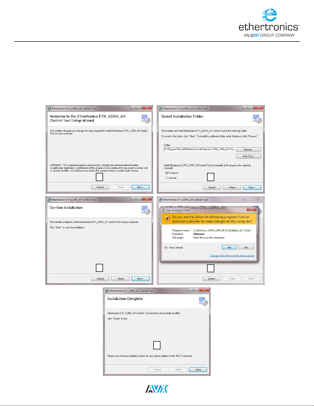
INSTALLING THE ETHERTRONICS CONTROL TOOL
Upon demand, Ethertronics can provide an installer type “.msi” of the control tool to communicate with the module.
Download the installer of the EtherLoRa Control Tool from the Ethertronics’ website or contact the developers from Ethertronics
Run the installer
The setup wizard will be displayed, click Next
Select the installation folder, click Next
After couples of seconds, User Account Control is displayed, please click OK
A shortcut with Ethertronics logo is created on the desktop automatically after the installation, user can run the tool using this shortcut
INSTALLATION WINDOWS
1
3
2
4
5
Figure 9
6
09 2419
Page 9
Application Note 006
Control Tool Quick Start Guide
QUICK START GUIDE
ETHERTRONICS CONTROL TOOL
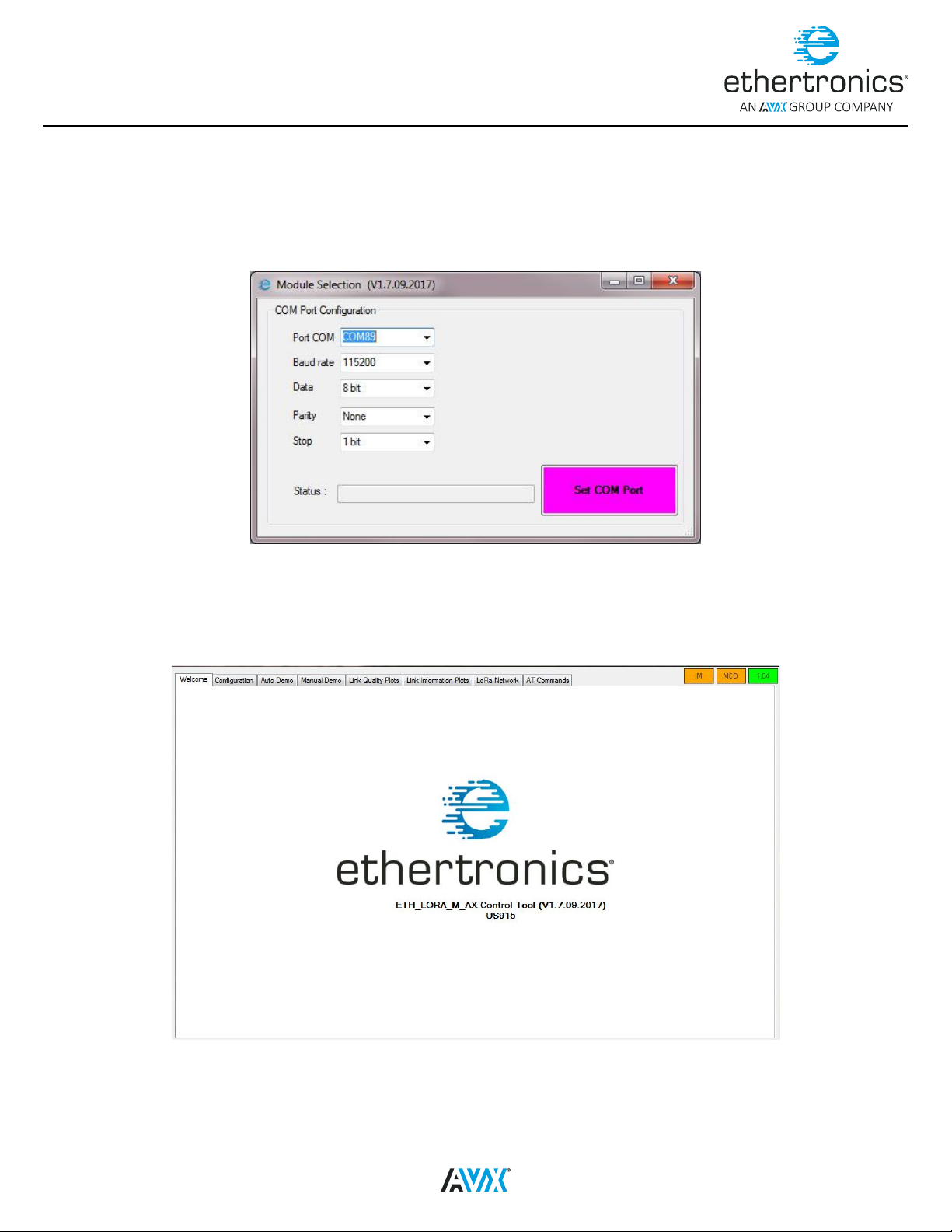
After launch the tool, the COM Port selection window is displayed. The default parameters on this window are correct, user does not need to change the serial
port parameters. User only needs to select the correct COM port from the combo box.
COM PORT SELECTION WINDOW
Figure 10
Once the button Set COM Port is clicked, the control tool will communicate with the ETH-LORA-M-AX-01 module to get the information about the module.
This will take up couples of seconds and the status will be displayed. If everything is OK, the main application form will be displayed. Otherwise the error will
be displayed.
WELCOME TAB
Figure 11
This welcome tab shows the name of the tool and as well as the version of the tool.
09 2419
7
Page 10
Application Note 006
Control Tool Quick Start Guide
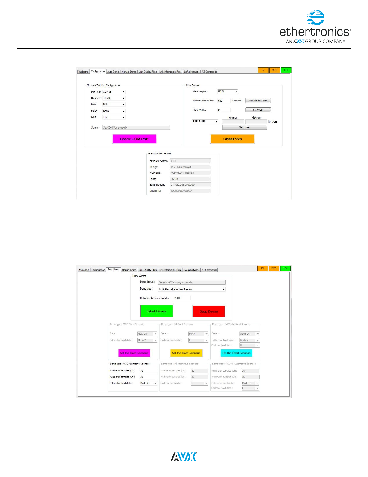
CONFIGURATION TAB
Figure 12
In this tab, user can verify the information about the detected module. Make sure that the Serial number is corresponding to the one written on the label on
top of the module. If there is any problem about the information of the module, user is advised to reset the module using the reset button (red push button on
the evaluation board) and click the check com port button to update the information or relaunch the tool. The plots control panel is used when the demo is
launched.
AUTO DEMO TAB
This tab is used to launch the demo of the algorithms in order to evaluate their performance. To use this tab user must have a LoRa gateway at disposition.
Otherwise the demo cannot be launch.
Figure 13
When the button Start Demo is clicked, if the module is not yet joined the network, the join procedure will be initiated. The join procedures will take up to ~45s.
The status of the current process will be displayed inside the status text box. If the selected demo type is not supported by the module, a message box will
be displayed. The MCD algorithm can only be evaluated on the active EVB. Once demo is correctly started, user can change to plots tab to see the plot of link
quality and information.
8
09 2419
Page 11
Application Note 006
Control Tool Quick Start Guide
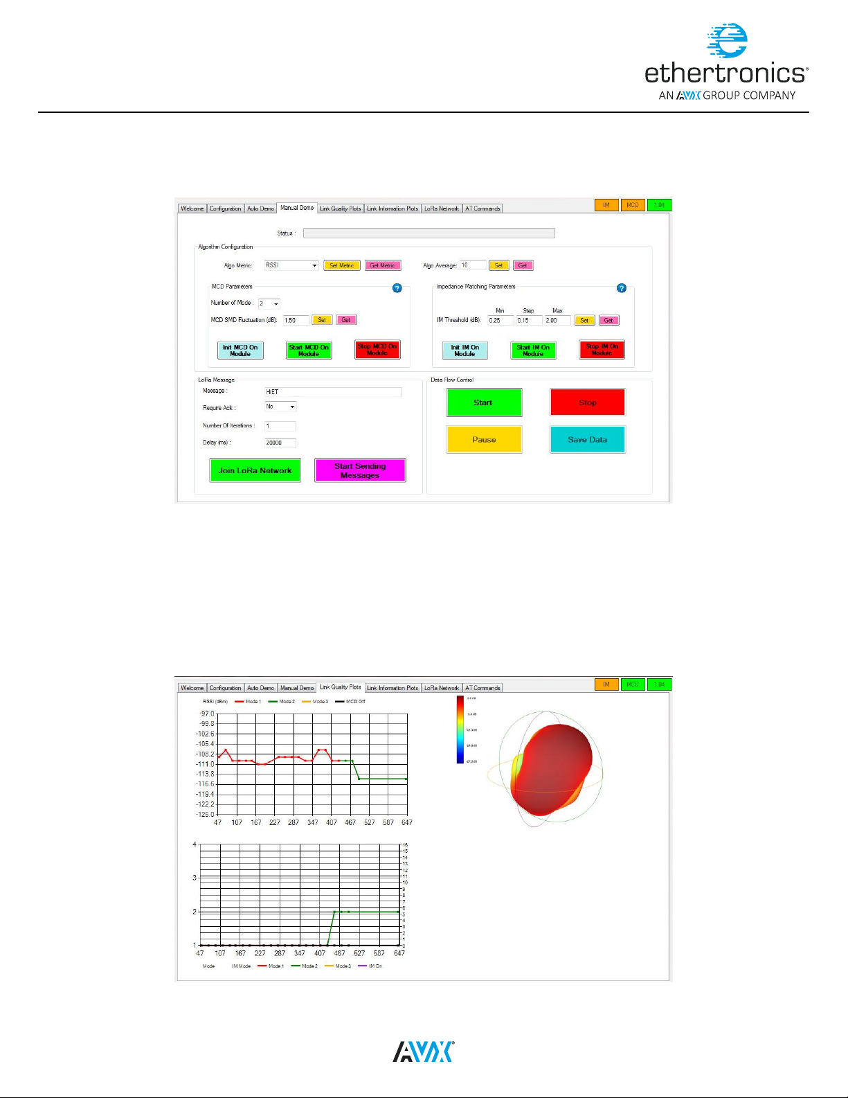
MANUAL DEMO TAB
Like the previous tab, this tab is used to launch the demo of the algorithms in order to evaluate their performance. In this tab, user must set all the parameters
of the algorithms, and launch them manually before starting to join the LoRa Network. After sending the message, user can start the data ow to evaluate the
algorithms. To use this tab user must have a LoRa gateway at disposition. Otherwise the demo cannot be launch.
Figure 14
In this tab, user has the liberty to change the default parameters of the algorithms before start the data ow. Once the parameters are set, user need to perform
the join procedure. If the join is successful, user can start the loop of sending message. In order to start the data ow, the number of iterations of the sending
message loop must be at least 15. If user wishes to send the message continuously, please set the number of iteration to “-1”. Then, user can start the data
ow. Once demo is correctly started, user can change to plots tab to see the plot of link quality and information.
LINK QUALITY TAB
This tab is only for display purpose. When the demo is correctly launched, user can see the display of the RSSI/SNR, radiation patterns and the algorithms’
result. To modify the axes of the plot, please go to Conguration Tab and adjust the values inside the Plots Control panel.
If the demo is not launched, these plots will not be displayed.
Figure 15
09 2419
9
Page 12
Application Note 006
Control Tool Quick Start Guide
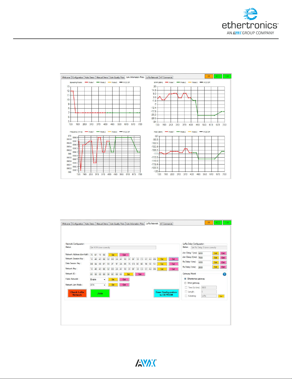
LINK INFORMATION TAB
This tab is only for display purpose. When the demo is correctly launched, user can see the display of the RSSI/SNR, spreading factor and the frequency. To
modify the axes of the plot, please go to Conguration Tab and adjust the values inside the Plots Control panel.
If the demo is not launched, these plots will not be displayed.
Figure 16
LORA NETWORK TAB
This tab is used to modify the LoRa parameter of the modules. Once the button Set or Get is click, user need to wait until the status of the current operation is
displayed inside status text box.
If user modies these parameters and wishes to save them even after the module reboots, user can store the new values inside the EEPROM of the module
using the button Save.
10
Figure 17
09 2419
Page 13
Application Note 006
Control Tool Quick Start Guide
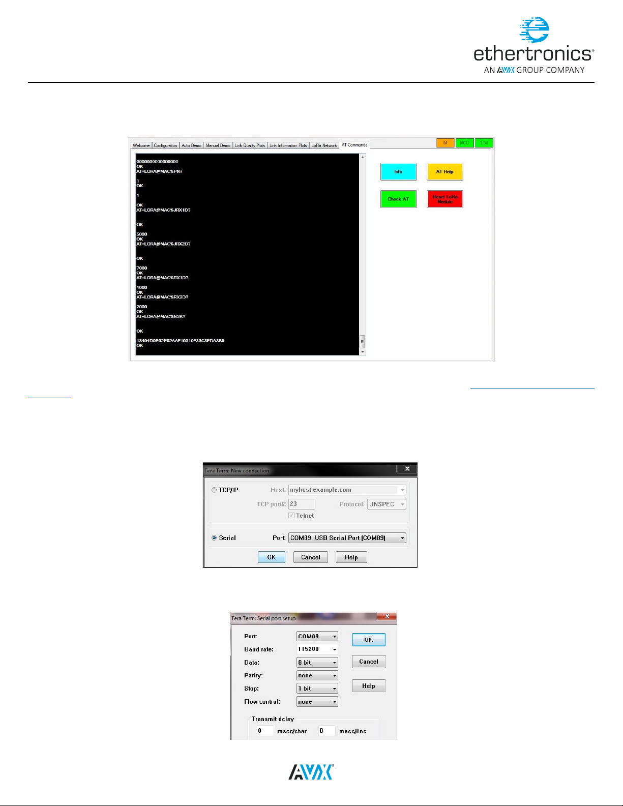
AT COMMANDS TAB
This tab is used to send AT command directly to the module. User can type the AT command inside the text box and use the Key Enter to send the command
to the module. The answer will be displayed.
Figure 18
For more information about the AT commands, please refer to LoRa_Module_AT Command Reference Guide document from www.avx.com/products/modules/
lora-module.
TERA TERM
An alternative tool to communicate with ETH-LORA-M-AX-01 is a serial port terminal. A free terminal like Tera Term can be used. Once the connection is done,
user can run the Tera Term application and the connection windows will be displayed automatically. Otherwise, user can open manually the new connection:
File New Connection Select the correct COM Port
Figure 19
User needs to change the parameters of the Serial COM port as follows:
Setup Serial port… adjust the parameters
Figure 20
09 2419
11
Page 14
Application Note 006
Control Tool Quick Start Guide
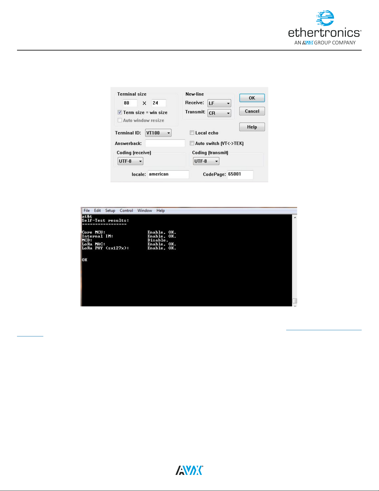
User can also adjust the setup of the terminal in order to have the answer correctly displayed
Setup Terminal... adjust New line receive to LF the terminal setup
TERA TERM TERMINAL SETUP WINDOW
Figure 21
When everything is set up, user can start sending AT command.
Figure 22
For more information about the AT commands, please refer to LoRa_Module_AT Command Reference Guide document from www.avx.com/products/modules/
lora-module.
12
09 2419
Page 15
Application Note 006
Control Tool Quick Start Guide
LIST OF ABBREVIATIONS
UART: Universal Asynchronous Receiver/Transmitter
USART: Universal Synchronous/Asynchronous Receiver/Transmitter
USB: Universal Serial Bus
TTL: Transistor–transistor logic level
EVB: Evaluation Boards
LoRa: Long range
OS: Operating System
VCP: Virtual COM Port
COM: Communication port
IM: Impedance Matching
MCD: Modal Cognitive Diversity
ISM: Industrial, Scientic and Medical
LIST OF FIGURES
Figure 1: Passive EVB (top view) ..............................................................................................................................................................................................................1
Figure 2: Passive EVB (bottom view) ........................................................................................................................................................................................................ 1
Figure 3: Active EVB (top view) ................................................................................................................................................................................................................. 2
Figure 4: Active EVB (bottom view) .......................................................................................................................................................................................................... 2
Figure 5: FTDI USB-UART Cable ................................................................................................................................................................................................................3
Figure 6: Connection between the FTDI UART cable and the passive EVB (side view) ......................................................................................................................... 4
Figure 7: Connection between the FTDI UART cable and the active EVB (side view)............................................................................................................................ 5
Figure 8: Device Manager Interface .......................................................................................................................................................................................................... 5
Figure 9: Installation windows .................................................................................................................................................................................................................. 6
Figure 10: COM Port Selection Window ................................................................................................................................................................................................... 7
Figure 11: Welcome Tab ............................................................................................................................................................................................................................ 7
Figure 12: Conguration Tab ..................................................................................................................................................................................................................... 8
Figure 13: Auto Demo Tab ......................................................................................................................................................................................................................... 8
Figure 14: Manual Demo tab ..................................................................................................................................................................................................................... 9
Figure 15: Link Quality Tab ........................................................................................................................................................................................................................ 9
Figure 16: Link Information Plots Tab ..................................................................................................................................................................................................... 10
Figure 17: LoRa Network tab ................................................................................................................................................................................................................... 10
Figure 18: AT Commands tab .................................................................................................................................................................................................................. 11
Figure 19: Tera Term New Connection window .....................................................................................................................................................................................11
Figure 20: Tera Term Serial Port setup window ..................................................................................................................................................................................... 11
Figure 21: Tera Term Terminal setup window ........................................................................................................................................................................................ 12
Figure 22: Tera Term window .................................................................................................................................................................................................................. 12
LIST OF TABLES
Table 1: EVB Passive components ...........................................................................................................................................................................................................2
Table 2: Active EVB components .............................................................................................................................................................................................................. 3
Table 3: FTDI Generic Cables Signal Descriptions ................................................................................................................................................................................... 3
Table 4: USB-UART cable and EtherLoRa connection .............................................................................................................................................................................. 4
Table 5: Toggle switch position ................................................................................................................................................................................................................ 4
13
09 2419
Page 16

Americas
Europe
Asia
+(1) 858.550.3820
FOLLOW US:
+33 (0) 4 93 74 30 71
Korea: 82.31.436.2290
China: 886.2.2655.7966
VISIT US AT WWW.AVX.COM
09 2419 -A
 Loading...