

Avtec Ventilation System Service Manual

OPERATOR MANUAL
IMPORTANT INFORMATION, KEEP FOR OPERATOR
This manual provides information for:
VENTILATION
SYSTEMS
NOTIFY CARRIER OF DAMAGE AT ONCE
It is the responsibility of the consignee to inspect the container upon receipt of
same and to determine the possibility of any damage, including concealed damage. Unified Brands suggests that if you are suspicious of damage to make a
notation on the delivery receipt. It will be the responsibility of the consignee to file
a claim with the carrier. We recommend that you do so at once.
Manufacture Service/Questions 888-994-7636.
Information contained in this document is known to be current and accurate at the time
of printing/creation. Unified Brands recommends referencing our product line websites,
unifiedbrands.net, for the most updated product information and specifications.
PART NUMBER OMANUAL_VMR-0507 Rev. A (0507)
1055 Mendell Davis Drive
Jackson, MS 39272
888-994-7636, fax 888-864-7636
avtecind.com

TABLE OF CONTENTS
4
4
4
5
5
5/6
6
6
7
7
7
9
9
9/10/11
13
13
13
13
13
13
13
13
13
14
15
15
15
15
15/16
16/17
16/17
17
17
17
17
17
17
17
17
17
17
17/18
17/18
18
18
18
18
19
19
19
19
20
20
20
20
22
A. Baffle Filter . .. . . . . . . . . . . . . . . . . . . . . . . . . . . . . . . . . . . . . . . . . . . . .
B. Modular Grease Extractors [Energy Aire] . . . . . . . . . . . . . . . . . . . . . . . . . . . . . . . .
C. Auto Wash [Energy Aire] . . . . . . . . . . . . . . . . . . . . . . . . . . . . . . . . . . . . . . . . . . . .
D. Airflow Requirements . . . . . . . . . . . . . . . . . . . . . . . . . . . . . . . . . . . . .. . . . . . . . . . .
E. Fire Extinguishing Systems .. . . . . . . . . . . . . . . . . . . . . . . . . . . . . . . . . . . . . . . . . . .
A. Ec oArch C anopi es . . . . . . . . . . . . . . . . . . . . . . . . . . . . . . . . . . . . . . . . . . . . . . . .
B. Ec oArch C anopi es With Ceiling Mounted Make-Up Air Plenum . . . . . . . . . . . . . .
A. Wall Attachment . . . . . . . . . . . . . . . . . . . . . . . . . . . . . . . . . . . . . . . . . . . . . . . . . . .
A. VCW Control Panel . . . . . . . . . . . . . . . . . . . . . . . . . . . . . . . . . . . . . . . . . . . . . . . . .
B. PAWS Control Panel . . . . . . . . . . .. . . . . . . . . . . . . . . . . . . . . . . . . . . . . . . . . . . . . .
C. Damper and Detectors . . . . . . . . . . . . . . . . . . . . . . . . . . . . . . . . . . . . . . . . . . . . . .
D. Ventilator Lights . . . . . . . . . . . . . . . . . . . . . . . . . . . . . . . . . . . . . . . . . . . . . . . . . . .
A. Hot Water Wash . . . . . . . . . . . . . . . . . . . . . . . . . . . . . . . . . . . . . . . . . . . . . . . . . .
B. Cold Water Mist [optional] . . . . . . . . . . . . . . . . . . . . . . . . . . . . . . . . . . . . . . . . . . . .
C. Drains . . . . . . . . . . . . . . . . . . . . . . . . . . . . . . . . . . . . . . . . . . . . . . . . . . . . . . . . . . .
D. Field Joints . . . . . . . . . . . . . . . . . . . . . . . . . . . . . . . . . . . . . . . . . . . . . . . . . . . . . .
E. Detergent Pump and Tank . . . . . . . . . . . . . . . . . . . . . . . . . . . . . . . . . . . . . . . . . . .
F. Interconnecting . . . . . . . . . . . . . . . . . . . . . . . . . . . . . . . . . . . . . . . . . . . . . . . . . . . .
G. Detergent Flow Chart . . . . . . . . . .. . . . . . . . . . . . . . . . . . . . . . . . . . . . . . . . . . . . . .
A. VCW Control Panel . . . . . . . . . . . . . . . . . . . . . . . . . . . . . . . . . . . . . . . . . . . . . . . . .
1. Adjustment . . . . . . . . . . .. . . . . . . . . . . . . . . . . . . . . . . . . . . . . . . . . . . . . . . . . . . . .
2. Sequence Of Operation . . . . . . . . . . . . . . . . . . . . . . . . . . . . . . . . . . . . . . . . . . . . .
3. Trouble-Shooting . . . . . . . . . .. . . . . . . . . . . . . . . . . . . . . . . . . . . . . . . . . . . . . . . . .
B. PAWS Control Panel . . . . . . . . . . . . . . . . . . . . . . . . . . . . . . . . . . . . . . . . . . . . . . . .
1. Manual Operation . . . . . . . . . . . . . . . . . . . . . . . . . . . . . . . . . . . . . . . . . . . . . . . . . . .
a. Fan Start . . . . . . . . . . . . . . . . . . . . . . . . . . . . . . . . . . . . . . . . . . . . . . . . . . . . . . . . .
b. Fan Stop . . . . . . . . . . . . . . . . . . . . . . . . . . . . . . . . . . . . . . . . . . . . . . . . . . . . . . . . .
c. Wash Start . . . . . . . . . . . . . . . . . . . . . . . . . . . . . . . . . . . . . . . . . . . . . . . . . . . . . . .
d. Wash Stop . . . . . . . . . . . . . . . . . . . . . . . . . . . . . . . . . . . . . . . . . . . . . . . . . . . . . . . .
2. Trouble Conditions . . . . . . . . . . . . . . . . . . . . . . . . . . . . . . . . . . . . . . . . . . . . . . . . . .
a. Low Detergent Indicator . . . . . . . . . . . . . . . . . . . . . . . . . . . . . . . . . . . . . . . . . . . . .
b. Supervised Valve [optional] . . . . . . . . . .. . . . . . . . . . . . . . . . . . . . . . . . . . . . . . . . . .
3. Hood Plenum Fire Protection . . . . . . . . . . . . . . . . . . . . . . . . . . . . . . . . . . . . . . . . . .
a. Automatic Operation . . . . . . . . . . . . . . . . . . . . . . . . . . . . . . . . . . . . . . . . . . . . . . . .
b. Manual Operation . . . . . . . . . . . . . . . . . . . . . . . . . . . . . . . . . . . . . . . . . . . . . . . . . . .
4. Programming Instructions . . . . . . . . . . . . . . . . . . . . . . . . . . . . . . . . . . . . . . . . . . . .
a . Setting The Clock . . . . . . . . . . . . . . . . . . . . . . . . . . . . . . . . . . . . . . . . . . . . . . . . . .
b. Setting The PAWS . . . . . . . . . . . . . . . . . . . . . . . . . . . . . . . . . . . . . . . . . . . . . . . . .
1. Single Wash Models . . . . . . . . . . . . . . . . . . . . . . . . . . . . . . . . . . . . . . . . . . . . . . . .
2. Multi-Wash Models . . . . . . . . . . . . . . . . . . . . . . . . . . . . . . . . . . . . . . . . . . . . . . . . .
c. Setting The Fire Delay . . . . . . . . . .. . . . . . . . . . . . . . . . . . . . . . . . . . . . . . . . . . . . . .
d. Reviewing The Daily Event Schedule . . . . . . . . . . . . . . . . . . . . . . . . . . . . . . . . . . . .
e. Changing The Daily Event Schedule . . . . . . . . . . . . . . . . . . . . . . . . . . . . . . . . . . . .
f. Repeating The Daily Event Schedule . . . . . . . .. . . . . . . . . . . . . . . . . . . . . . . . . . . .
g. Holiday Feature . . . . . . . . . . . . . . . . . . . . . . . . . . . . . . . . . . . . . . . . . . . . . . . . . . . .
h. Fan On During Recovery . . . . . . . . . . . . . . . . . . . . . . . . . . . . . . . . . . . . . . . . . . . . .
i. Power Loss . . . . . . . . . . . . . . . . . . . . . . . . . . . . . . . . . . . . . . . . . . . . . . . . . . . . . . .
j. Last Command Indicator . . . . . . . . . . . . . . . . . . . . . . . . . . . . . . . . . . . . . . . . . . . . .
k. Diagnostic Indicators . . . . . . . . . . . . . . . . . . . . . . . . . . . . . . . . . . . . . . . . . . . . . . .
l. Detergent Pump and Tank . . . . . . . . . . . . . . . . . . . . . . . . . . . . . . . . . . . . . . . . . . .
2 OM-VMR

A. Baffle Filter . . . . . . . . . . . . . . . . . . . . . . . . . . . . . . . . . . . . . . . . . . . . . . . . . . . . . . .
B. Modular Grease Extractors . . . . . . . . . . . . . . . . . . . . . . . . . . . . . . . . . . . . . . . . . .
C. Auto Wash Grease Extractors . . . . . . . . . . . . . . . . . . . . . . . . . . . . . . . . . . . . . . . .
D. Air Adjustment Baffle . . . . . . . . . . . . . . . . . . . . . . . . . . . . . . . . . . . . . . . . . . . . . . .
E. Fire Dampers . . . . . . . . . . . . . . . . . . . . . . . . . .. . . . . . . . . . . . . . . .. .. . . . . . . .. .. .
F. Air Make-Up [Supply] Plenums . . . . . . . . . . . . . . . . . . . . . . . . . . . . . . . . . . . . .. .. .
G. Auto Wash . . . . . . . . . . . . . . . . . . . . . . . . . . . . . . . . . . . . . . . . . . . . . . . . . . . . . .
H. Cold Water Mist [Optional] . . . . . . . . . . . . . . . . . . . . . . . . . . . . . . . . . . . . . . . . . .
I. Lights . . . . . . . . . . . . . . . . . . . . . . . . . . . . . . . . . . . . . . . . . . . . . . . . . . . . . . . . . .
A. Baffle Filters . . . . . . . . . . . . . . . . . . . . . . . . . . . . . . . . . . . . . . . . . . . . . . . . . . . . . .
B. Modular Grease Extractors . . . . . . . . . . . . . . . . . . . . . . . . . . . . . . . . . . . . . . . . . .
C. Grease Trough . . . . . . . . . . . . . . . . . . . . . . . . . . . . . . . . . . . . . . . . . . . . . . . . . . .
D. Grease Collection Receptacle . . . . . . . . . . . . . . . . . . . . . . . . . . . . . . . . . . . . . . . .
E. Hood Canopy . . . . . . . . . . . . . . . . . . . . . . . . . . . . . . . . . . . . . . . . . . . . . . . . . . . . .
F. Detergent System . . . . . . . . . . . . . . . . . . . . . . . . . . . . . . . . . . . . . . . . . . . . . . . . .
G. Fusible Link Replacement . . . . . . . . . . . . . . . . . . . . . . . . . . . . . . . . . . . . . . . . . .
A. PAWS Panel - Electrical . . . . . . . . . . . . . . . . . . . . . . . . . . . . . . . . . . . . . . . . . . . .
B. VCW Panel - Electrical . . . . . . . . . . . . . . . . . . . . . . . . . . . . . . . . . . . . . . . . . . . .
C. PAWS/VCW Panel - Plumbing . . . . . . . . . . . . . . . . . . . . . . . . . . . . . . . . . . . . . .
D. EVAC Detergent . . . . . . . . . . . . . . . . . . . . . . . . . . . . . . . . . . . . . . . . . . . . . . . . . .
E. Electro-Mechanical Damper . . . . . . . . . . . . . . . . . . . . . . . . . . . . . . . . . . . . . . . . .
F. Fusible Link Damper . . . . . . . . . . . . . . . . . . . . . . . . . . . . . . . . . . . . . . . . . . . . . . .
G. Hood Canopy . . . . . . . . . . . . . . . . . . . . . . . . . . . . . . . . . . . . . . . . . . . . . . . . . . .
SGNIWARDDNAATADREHTO.X
A. EVAC Cleaner Cut Sheet . . . . . . . . . . . . . . . . . . . . . . . . . . . . . . . . . . . . . . . . . . .
B. Air Movement Recordings . . . . . . . . . . . . . . . . . . . . . . . . . . . . . . . . . . . . . . . . . .
C. Calculating and Recording Air Movement Readings . . . . . . . . . . . . . . . . . . . . . .
D. Calculating and Recording Air Movement . . . . . . . . . . . . . . . . . . . . . . . . . . . . . .
22
22
22
23
23
24
24
25
25
25
25
25
25
25
26
26
26
26
27
27
27
27
28
28
29
29
30
30
31
32
33
34
OM-VMR 3
1
I. TYPES OF SYSTEMS
This manual covers three [3] of the basic types of
systems offered by AVTEC - Baffle Filter [AF],
Modular Grease Extractor [AX] and Auto W ash
Down [AW].
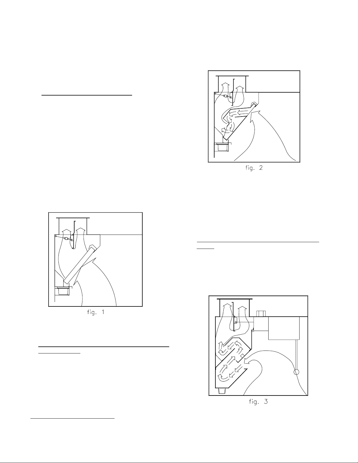
A.Baffle Filter [AF Series] [See fig. #1
]
Model AF ventilators are listed by Underwriters
Laboratories Inc. [UL] and are built in accordance
with the National Fire Protection Association
[NFPA] Standard No. 96 for use with UL Listed
fire extinguishing systems for duct hood
protection. They are available with or without an
automatic exhaust fire damper. They utilize UL
Classified removable baffle filters to extract
grease and provide a limited fire barrier. The
canopy contains an integral grease trough and
removable grease receptacle(s). Surface,
plenum and duct collar fire extinguishing systems
may be factory supplied.
Vent Control Panels may be supplied with these
systems. See additional wiring diagrams for
options.
Installation shall be in accordance with NFPA 96.
B.Modular Grease Extractors [AX Series] Energy
Aire [see fig. #2]
Model AX ventilators are listed by UL and built in
accordance with NFPA Standard No. 96 for use
with UL Listed fire extinguishing systems for duct
and hood protection. They are available with or
without an automatic exhaust fire damper.
These models utilize high velocity removable
grease extractors. This exclusive design extracts
up to 95%* of airborne grease contaminants. The
1
*Data from independent tests not a part of UL test
procedure.
canopy contains an integral grease trough and
grease collection receptacle(s). Surface, plenum
and duct collar fire extinguishing systems are
required and may be factory supplied.
Vent control panels may be supplied with these
systems. See additional wiring diagrams for
options.
Installation shall be in accordance with NFPA 96.
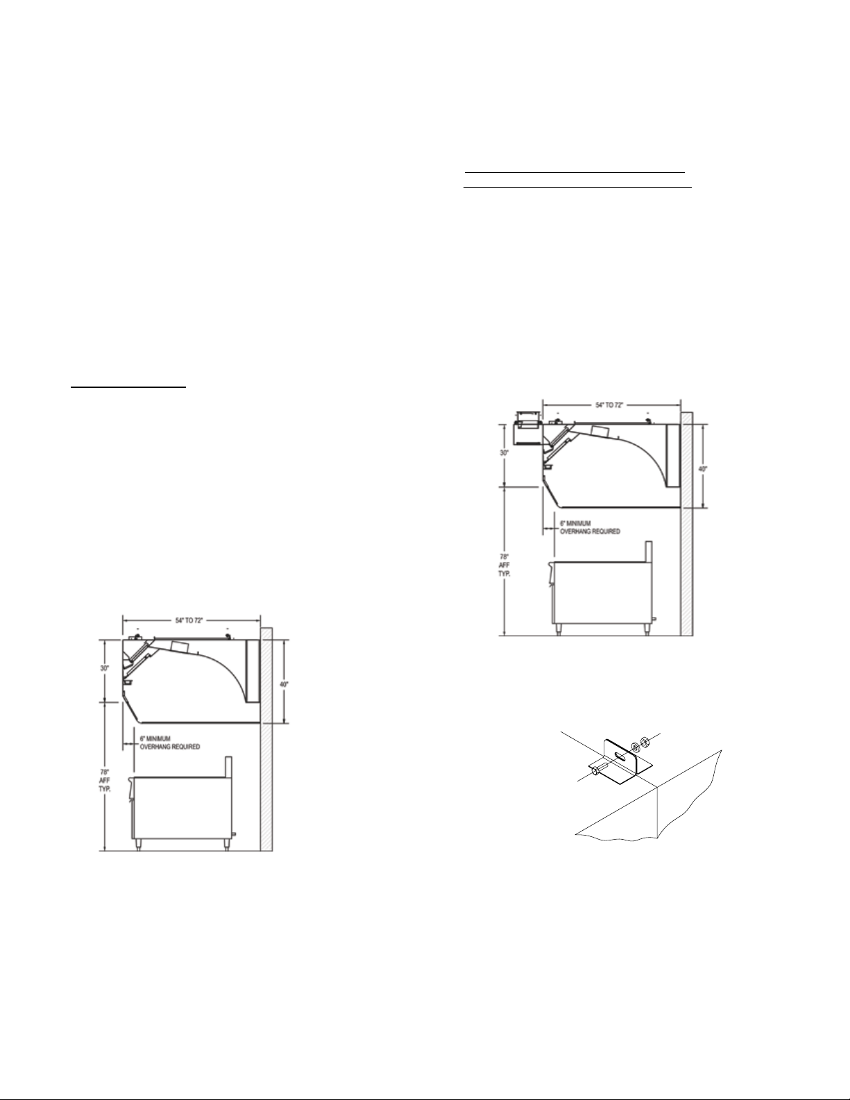
C.Auto Wash Down [AW Series] Energy Aire [see
fig. #3]
Model AW ventilators are listed by UL and built in
accordance with NFPA Standard No. 96 for use
with UL Listed fire extinguishing systems for duct
and hood protection. They are available with or
without an automatic exhaust fire damper.
These systems utilize a high velocity grease
extractor. This exclusive design extracts up to
95%* of airborne grease contaminants. An
4 OM-VMR

integral water wash system cleans the inside of
the grease extraction chamber either by manual
activation of the Wash Start button or by a
programmable timer. The duration of the wash is
electrically controlled. The wash system is also
activated by an electrical thermostat or a manual
switch in the event of a fire condition. A surface
fire extinguishing system is required and may be
factory supplied.
Auto Wash control panels are provided with these
systems. Wiring diagrams are provided with this
manual.
Installation shall be in accordance with NFPA 96.
D.Airflow Requirements
Minimum exhaust airflow requirements and
maximum make-up airflow requirements [where
air is introduced directly inside the canopy] are
shown on the chart below. These flow rates were
established under laboratory conditions. Greater
exhaust airflows and/or reduced make-up airflows
may be required for complete capture.
CFM REQUIREMENTS
400°F Cooking 600°F Cooking 700°F Cooking
Model No. Surface Equip. Surface Equip. Surface Equip.
AFWO,AFBO 200 300 525
AFDO,AFWP
AFBP,AFDP
AFWE,AFDE
AFBE
AFWI,AFBI 250[175] N/R N/R
AFDI,AFWD
AFBD,AFDD
AFIO,AFIP 250 400 600
AFIE
AFII,AFID 300[150] N/R N/R
AXWO,AXBO 200 275 525
AXDO,AXWP
AXBP,AXDP
AXWE,AXDE
AXBE
AXWI,AXBI 250[175] N/R N/R
AXDI,AXWD
AXBD,AXDD
AXIO,AXIP 250 400 600
AXII 300[150] N/R N/R
AWWO,AWWP 194 270 *525
AWWE,AWDO
AWDP,AW DE
AWBO,AW BP
AWBE
AWWI,AWBI 250[190] 270[146] N/R
AWDI,AWWD
AWBD,AW DD
AWTE,AW TP 400 420 N/R
AWTO
N/R = Not Recommended
*=Manufacturer's test results not yet submitted to U.L. for capture tests.
E.Fire Extinguishing Systems
There are two basic types of ventilator fire
extinguishing systems in use today:
Wet Chemical and Water Mist. Wet Chemical
Systems may be all or partially factory installed
[by the Fire System Manufacturer]; final hook up
and certification at job site is done by the Fire
System Manufacturer's local representative.
These systems must be periodially inspected,
and critical parts replaced. It is suggested that a
service contract be purchased from the local
representative. For further details refer to the
manufacturer's technical manual.
AVTEC manufactures and installs a water mist
fire extinguishing system, "MIST-A-FIRE", that
connects to the building fire sprinkler system
[must be "wet" type system]. Final connect of this
system must be done in the field by the sprinkler
contractor or authorized plumber. A
certification/inspection report is done by an
authorized AVTEC representative. Periodic
inspection is generally required, but replacement
of parts and periodic maintenance is virtually
eliminated. For further details, refer to the
AVTEC MIST-A-FIRE Installation and Operating
Technical Manual.
II. INSTALLING THE VENTILATOR
The ventilator is supplied with brackets to facilitate
the attachment of hanger rods to the vent. Hanger
rods should be attached to all brackets to ensure
proper support.
A.Ascertain that the ceiling/roof structure is strong
enough to support the weight of the hood and
support system. The approximate weight of the
hood is shown below:
45 lbs/linear ft. for hoods w/o AMU plenums.
55 lbs/linear ft. for hoods w/AMU plenums.
125 lbs for fire control cabinet.
B.Carefully uncrate the hood so as not to dent or
scratch the outer surface.
C.Position the hood on the floor in approximately
its final installed location.
D.Use 1/2" threaded rods to hang the hood. The
hanger rods should be approximately 1/2" closer
to the wall at the structural attachment location
than at the top of the hood. [see fig. #4] This
ensures that the hood is held tightly against the
wall.
Note! Do not remove
Support Brace until Ventilator
installation is complete. Upon completion of
installation, dispose of Support Brace and replace the
Acorn Nuts to their original locations.
OM-VMR 5
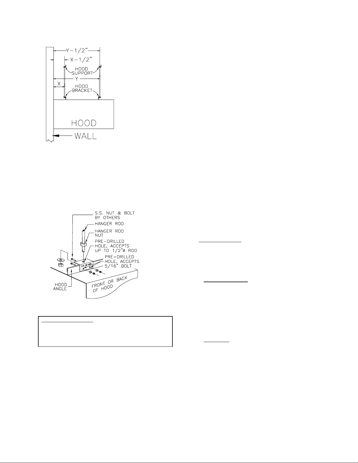
Fig 4
E.The hood should be hung so that the bottom of the
hood is 6'-6" above the finished floor unless otherwise
specified. Carefully lift the hood into position being
certain to avoid scratching the finished surfaces.
Install 1/2" threaded rod from each bracket and the
structural support. Secure rods with heavy duty nuts.
[see fig. #5] Be sure that the hood is level.
Fig 5
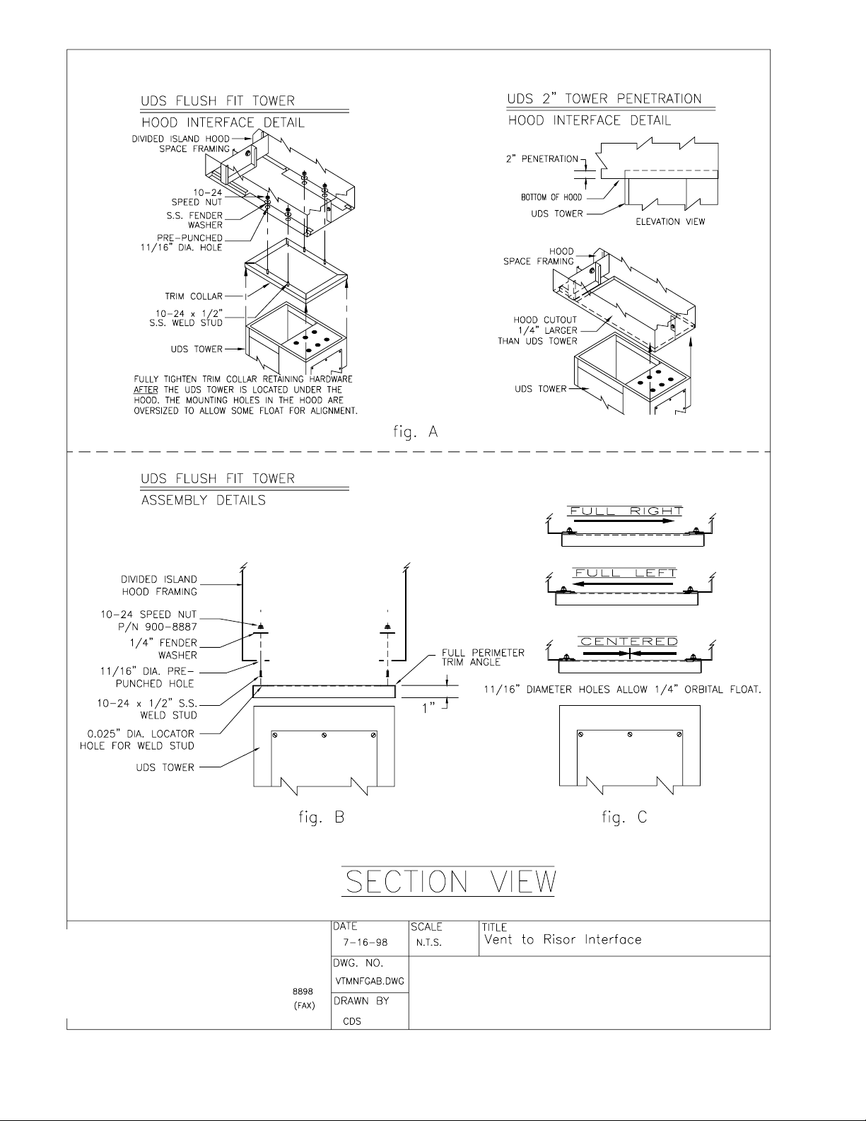
Tower Interface Detail
Place trim collar on tower. Position tower under hood.
Fully tighten trim collar retainer hardware after tower
and hood are aligned properly. See fig. A, B, and C
(next page).
F.The entire exhaust duct system must be con-
tinuously welded. This includes the connection
to the duct collar and the roof curb. All welds
must be liquid tight.
NOTE: Welds must not impede operation of
damper.
G.Connect the lights to the circuit breaker panel
through the light switch. All connections should
be in compliance with NFPA 70, National Electric
Code [NEC].
H. Install bulbs in the light fixture[s].
I.Install the grease filters [AF] or modules [AX].
J.Install the grease receptacles [AF or AX]
NOTE: A minimum of a three inch [3"] insulated
fire barrier and air space must be maintained
between the capture area skin of the ventilator
and any combustible surface, including wall and
ceiling. AVTEC ventilators normally have a 3" air
space; insulation is added when specified.
III.CONTROL PANEL [if provided]
Control panels are provided with all auto wash type
ventilators [Models AW- ] and are optional with the
baffle filter type [AF- ] and modular grease
extractor type [AX- ]. Control panels with Models
AF- and AX- do not have the auto wash plumbing
assembly compartments. Any control panel may
be provided with a integral MIST-A- FIRE
Extinguishing System alarm panel and sprinkler
assembly piping; refer to the MIST-A-FIRE
technical manual.
A.Wall Attachment
Control panel dimensions and connection detail
are shown on the enclosed shop drawing.
Panels may be surface mounted, partially
recessed or fully recessed as shown on fig. 6.
1.Surface Mounted
Drill four [4] holes in ventilator plumbing
compartment as required. Be careful not to
damage any components. Avoid drilling into
electrical compartments. Bolt to wall with
anchor bolts or other acceptable means.
Weight of control panel varies from 90 lbs. to
200 lbs.
2.Recessed
Cut hole in wall 1/2" greater than O/A
dimensions of control box [shown on shop
drawing]. Spacers or support angles may be
necessary to provide proper support. It is
recommended that panel be bolted to wall
similar to method used for surface mounted
above.
6 OM-VMR
ECOARCH HOOD MODELS
The Avtec EcoArch is the latest addition in premium ventilation
systems that continues Avtec’s reputation as an innovative,
technology leader focused on providing solutions for our
customers needs. The combination of the patent pending
arch top and the front mounted high velocity exhaust slot
reduces the amount of exhausted CFM by 45% compared to
traditional CFM rates. This translates into an annual electric
and gas savings of up to 40%.
INSTALLATION INSTRUCTIONS
All EcoArch hoods by Avtec are provided with hanging brackets
designed to receive ½” threaded rod with a ½” bolt and washer.
Supporting rods (provided by others) must be connected to all
factory installed brackets. Recommended hanging height is
between 6’-6” and 7’-0” above the nished oor.
ALL AVTEC VENTILATION SYSTEMS MUST BE INSTALLED
IN ACCORDANCE WITH NFPA-96 REMOVAL OF SMOKE
AND GREASE-LADEN VAPORS FROM COMMERCIAL
COOKIGN EQUIPMENT.
A. EcoArch Canopies
1. Check all local codes prior to installation. Special
requirements may be necessary depending upon
building construction.
8. For make-up air hoods, the supply collar with built-in
UL listed re damper and air volume damper must be
installed per instructions on collar.
9. Provide a removable service door in supply duct near
re damper.
B. EcoArch Canopies equipped with a
Ceiling Mounted Make up Air Plenum
If your EcoArch hood comes equipped with a ceiling
mounted make up air plenum please refer to the following steps.
Follow steps 1-3 as outlined at left.
4. Suspend hood from adequate roof supports using ½”
threaded rods with nuts and washers.
5. Level hood left to right and front to back.
6. The make up air plenum is designed to mount against
the front face of the hood.
2. Move crated hood to location of installation and very
carefully uncrate hood.
3. Front Mounted Exhaust Plenum: The EcoArch is
different from almost all other kitchen exhaust hoods on
the market today. The exhaust plenum is in the front of
the hood versus the traditional rear location to minimize
exhausted kitchen air and for easier and safer access
to the lter medium for cleaning and/or replacement.
Refer to drawing before proceding to step 4.
4. Suspend hood from adequate roof supports using 1/2”
threaded rods with nuts and washers.
5. Level hood left to right and front to back.
6.
Brackets are provided for hoods which are to be installed
end to end or back to back. Bolt brackets together using
3/8” bolt through holes provided. (See Fig. 6 at right)
7. Install C channel where the ends of the hood meet and
install T moldings on front face of hoods where they
join. High temperature silicone can be used to install C
channel and T moldings.
7. Brackets are provided at the top front of the hood and
the top of the make-up air plenum box. Bolt brackets
together using 3/8” bolt through holes provided. (See
Fig. 6)
Fig 6
8. Install C channel where the ends of the hood meet
and install T moldings on front face of hoods where
they join. High temperature silicone can be used to
install C channel and T moldings.
9. For make-up air hoods, the supply collar with built-in
UL listed re damper and air volume damper must be
installed per instructions on collar.
10. Provide a removable service door in supply duct near
re damper.
OM-VMR 7
8 OM-VMR
IV. ELECTRICAL CONNECTIONS
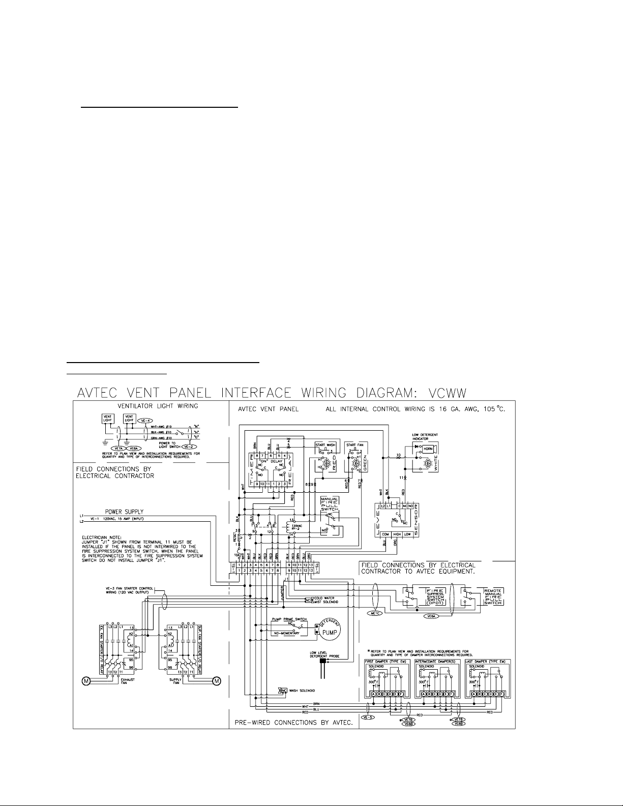
A.VCW Control Panel [Refer to fig. 7]
1.Typical field connection terminals for VCW
Control Panel are shown in fig. 7. For custom
features such as sequential wash, time delay,
etc. refer to AVTEC shop drawing in back of
this manual.
2.Terminals No. 1 and No. 2 are for the
120vac Power Supply. Terminal No. 1 is Hot
and Terminal No. 2 is Neutral.
3.Terminals No. 3 and No. 4 are 120vac
power for the Water Solenoid and Detergent
Pump. These terminals are "hot" whenever
the Water Wash Solenoid and the Detergent
Pump is scheduled to be "ON" or when there
is a fire condition. Terminal No. 5 provides
power for a pump/prime switch with a
momentary closed/normally open contact.
This switch is helpful in checking the
performance of the pump as well as in
priming the pump.
B.Programmable Automatic Wash Sequence
[PAWS] Control Panel
1.Typical Field Connections for the PAWS
Control Panel are shown on [figs. 10, 11, and
12]. Note that all options and connections may
not be included on your system.
2.Terminal Block #1 [TB-1] has three [3]
terminals and is located on the right-hand side of
the Input/Output [I/O] Board. Terminal #1
[uppermost] is for the Hot lead of the power
supply and is protected by a fuse located within
the panel. Terminal #2 [center] is for the Neutral
lead of the power supply. Terminal #3
[lowermost] is used to ground the Input/Output
Board to the Control Panel Housing.
Terminal No. 4 is Hot and Terminals No. 2 & 3
are Neutral.
3.Terminals No. 3 and No. 6 carry 120vac
whenever the fans are scheduled to be ON.
They are used to activate the fan contactor[s]. In
the event of a fire situation, power is removed
from Terminal 5 which provides power for
Terminal No. 6. Terminal No. 6 is the Hot lead
and Terminal No. 3 is Neutral.
7.giF
OM-VMR 9
4.Terminal Block #2 [TB-2] has three [3] pairs of
terminals and is located at the upper right corner
of the Input/Output Board. The first pair of
terminals are for the number one wash valve
solenoid. This will be the only wash output
active in a P-10-__ or P-15-__ Control Panel.
The second pair of terminals are for the number
two wash valve solenoid. The third pair of
terminals are for the number three wash valve
solenoid.
5.Terminal Block #3 [TB-3] has three [3] pairs of
terminals. It will not be present on P-10-__ or P15-__ Control Panels. The first pair of terminals
are for wash valve solenoid number four. The
second pair of terminals are for the number five
wash valve solenoid. The third pair of terminals
are for the number six wash valve solenoid.
6.Terminal Block #4 [TB-4] has three [3] pairs of
terminals. It will not be present on P-10-__ or P15-__ Control Panels. The first pair of terminals
are for the number seven wash valve solenoid.
The second pair of terminals are for the number
eight wash valve solenoid.
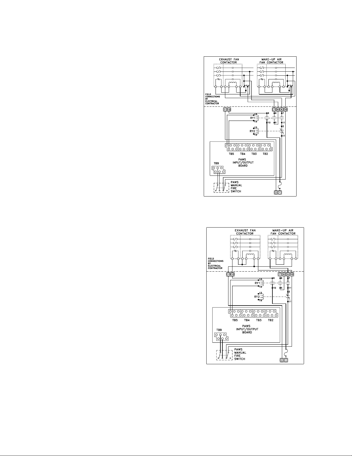
7.Terminal Block #5 [TB-5] has three [3] pairs of
terminals. The first pair provides power for the
detergent pump. The second pair provides
power for the PAWS Alarm/Trouble horn. [The
third pair provides power for the vent fan
contactors. [see figs. #8a & 8b]
Note that the maximum output is one-and-onehalf [1-1/2] amperes. If the total inrush current
for all contactors will exceed this limit, an
intermediate relay must be used.
8.Terminal Block #9 [TB-9] has three [3] pairs of
terminals and is located at the lower left corner of
the Input/Output Board. The first pair of
terminals are for connection to the optional
supervised shut-off valve. If the panel is not
equipped with this option, a jumper wire must be
installed. The second pair of terminals are for
connection to the Manual Fire Switch. The third
pair of terminals are for connection to the
automatic fire switch contacts terminals are for
connection to the automatic fire switch contacts.
Fig 8a
Fig 8b
10 OM-VMR
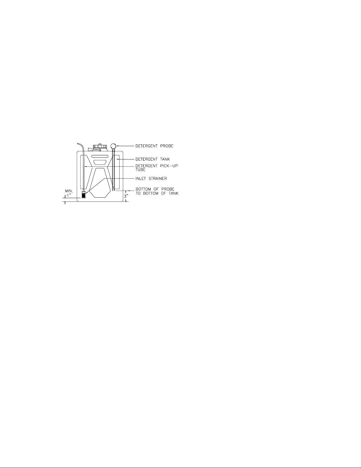
9.Terminal Block #11 [TB-11] has three [3] pairs of
terminals. The first pair of terminals are low voltage
connections for the detergent low level probe. The
probe should be installed in the detergent container
so that it does not protrude above the top of the
detergent pump inlet strainer. [fig. #9] This is
intended to prevent cavitation of the pump and will
advise when the tank needs to be refilled. The probe
rods may be cut to facilitate a neat and effective
installation.
Fig 9
10.Terminal Block #12 [TB-12] has three [3] pairs
of terminals. The first pair of terminals are for
connection to the optional battery.
OM-VMR 11
 Loading...