

Page 1
CT ACTIVE
POWERED SPEAKERS
Order ref: 170.254, 170.257, 170.260, 170.263, 170.266
User Manual
Page 2
Introduction
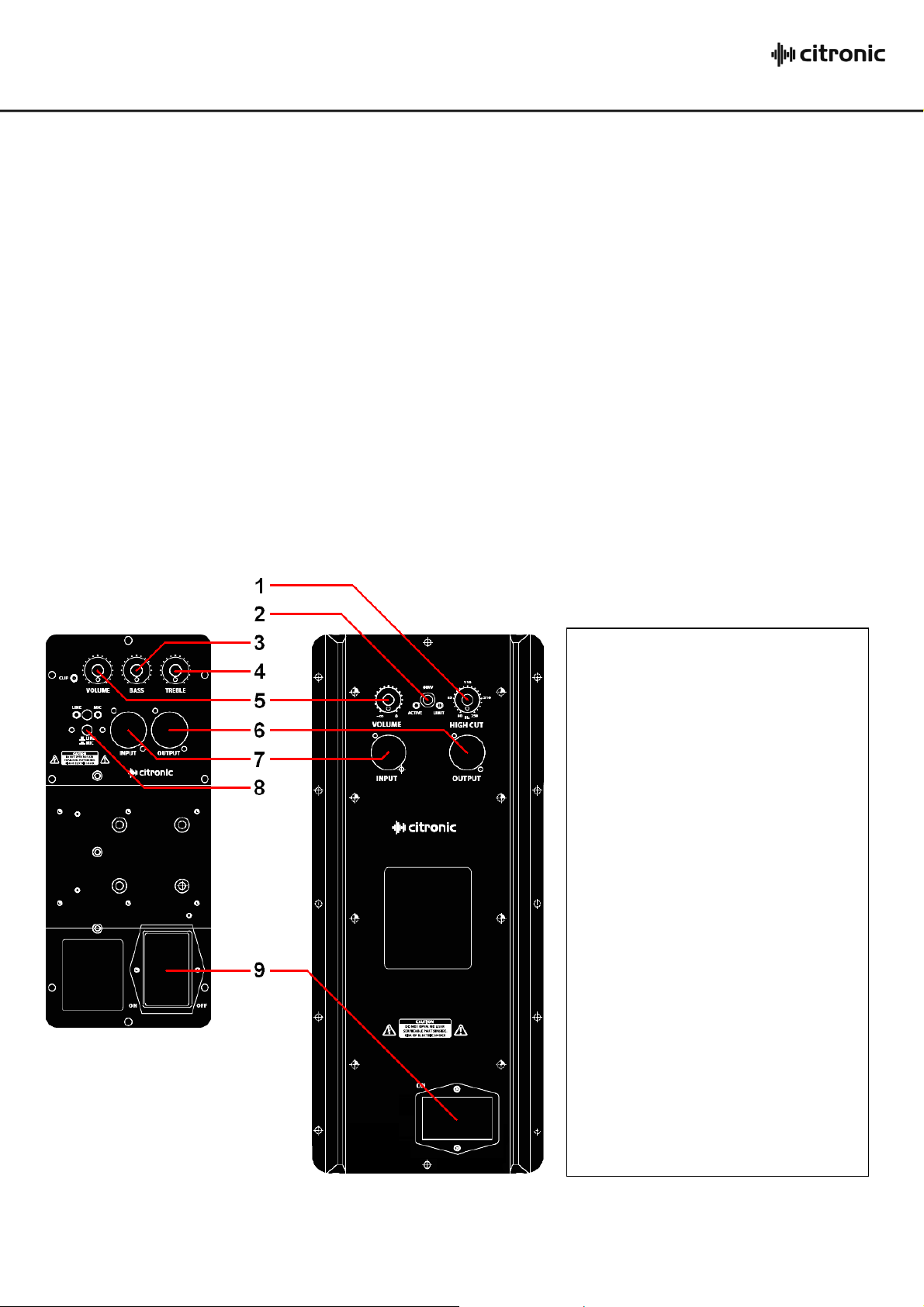
1. HI CUT control (170.266 only)
Adjusts cutoff frequency of sub filter
2. INV switch (170.266 only)
Polarity invert function
3. BASS control (not 170.266)
Adjusts low frequency level
4. TREBLE control (not 170.266)
Adjusts high frequency level
5. VOLUME control
Adjusts overall output level
6. OUTPUT XLR
Signal output (balanced)
7. INPUT XLR
Signal input (balanced)
8. MIC/LINE switch (not 170.266)
Selects Mic or Line level for input
9. MAINS inlet and power switch
Combined IEC inlet, fuse holder and
power switch
Thank you for choosing the Citronic CT-series active speakers as part of your sound reinforcement system. These high output cabinets are designed to
offer high quality, dependable service for mobile and installed systems. Please read this manual fully and follow the instructions to achieve the best
results with your new purchase and to avoid damage through misuse.
Warning
To prevent the risk of fire or electric shock, do not expose any of the components to rain or moisture.
If liquids are spilled on the casing, stop using immediately, allow unit to dry out and have checked by qualified personnel before further use. Avoid
impact or extreme pressure to the case
No user serviceable parts inside – Do not open the case – refer all servicing to qualified service personnel.
Safety
Check for correct mains voltage and condition of IEC lead before connecting to power outlet
Ensure signal leads are good condition with no short connections or damaged plugs
Placement
Position on a stable surface or pole mount stand. If suspended by flying points, ensure fixings are adequate for the weight load.
Keep away from heat sources and away from damp or dusty environments
Ensure adequate access to controls and connections
Cleaning
Use a soft dry or slightly damp to clean the cabinet as required
Do not use strong solvents for cleaning the unit
Amplifier Panel
CT Active Speakers User Manual
Page 3

Connection
Connect line level signal from sound source to the INPUT XLR, ensuring that the MIC/LINE switch is in the out position (LINE).
Alternatively, a microphone can be connected to the INPUT XLR and the MIC/LINE switch should be pressed in (MIC - note: not available on 170.266)
Connect the OUTPUT XLR to any further active speakers that are to be fed the same signal.
Connect the supplied mains cable from the IEC connector to a suitable mains outlet, ensuring correct voltage and adequate current capacity.
Operation
CT8A, CT10A, CT12A, CT15A (170.254, 170.157, 170.260, 170.263)
With VOLUME control turned fully down, switch on the power switch.
Ensure a signal is playing to the input and gradually increase the VOLUME control to the required output level.
BASS and TREBLE controls may be adjusted to the desired tonal response.
Bear in mind that the combined adjustment of these may affect the output level and VOLUME settings may need to be adjusted to compensate.
The red CLIP LED will illuminate if the output is reaching clip level.
If the red CLIP LED illuminates more than very briefly, reduce the volume until it illuminates only briefly on loud peaks in the sound.
Before powering down, turn the channel gain controls fully down to avoid loud noises when switching off.
CT15SA (170.266)
With VOLUME control turned fully down, switch on the power switch.
Ensure a signal is playing to the input and gradually increase the VOLUME control to the required output level.
Adjusting the HIGH CUT control varies the cutoff frequency of the high cut filter.
Lower settings allow only the lowest frequencies to be output and higher settings allow more low-mid frequencies to be introduced into the signal.
The INV switch reverses polarity when pressed in, which may help to avoid low frequency feedback or phase align 2 subs facing toward each other.
The correct setting for this switch is whichever produces the best output or lowest feedback and is subject to trial and error.
ACTIVE LED shows that a signal is present and LIMIT indicates that the internal clip limiter is operating.
If the LIMIT LED lights persistently, the VOLUME setting may need to be turned down.
Before powering down, turn the channel gain controls fully down to avoid loud noises when switching off.
CT Active Speakers User Manual
Page 4
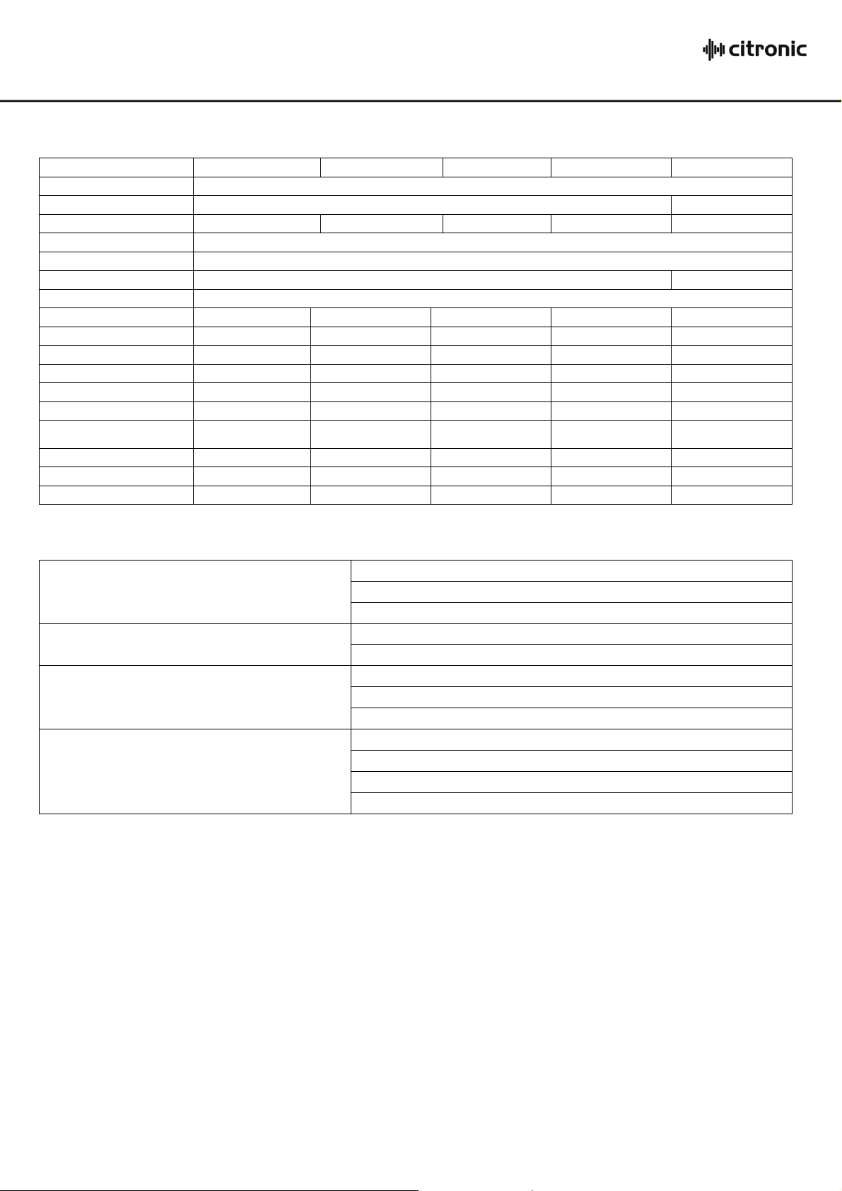
Model
CT8A
CT10A
CT12A
CT15A
CT15SA
Power supply
230Vac, 50Hz
Top hat
Base mounted 35mmØ
Top mount 35mmØ
Horn Driver
Titanium compression
N/A
Connector
XLRF input, XLRM output
Sensitivity
775mV
System
2-way full range
Sub woofer
THD
<0.04%
Woofer
20cm (8“)
25cm (10“)
30cm (12“)
38cm (15“)
38cm (15“)
Tweeter
2.5cm (1“)
2.5cm (1“)
4.4cm (1.75“)
4.4cm (1.75“)
N/A
Power rms
100W + 50W
100W + 50W
300W + 100W
300W + 100W
400W
Dispersion
90 x 60°
90 x 60°
50/100 x 55°
50/100 x 55°
N/A
Flying Points
6 x M6
6 x M6, 4 x M8
10 x M8
10 x M8
10 x M8
Frequency response : -3dB
65Hz - 18kHz
55Hz - 18kHz
50Hz - 18kHz
40Hz - 18kHz
40Hz - 250Hz
Frequency response : 10dB
60Hz - 20kHz
50Hz - 20kHz
40Hz - 20kHz
35Hz - 20kHz
35Hz - 250Hz
Max. SPL
116dB
116dB
118dB
120dB
120dB
Dimensions
405 x 275 x 265mm
464 x 321 x 321mm
620 x 415 x 391mm
700 x 485 x 460mm
700 x 485 x 460mm
Weight
8.6kg
10.5kg
23kg
30.5kg
30.5kg
No power light on rear panel switch
Ensure IEC inlet is connected to mains and mains lead is in good condition
Ensure mains outlet is switched on
Check mains fuse. If repeatedly blowing, refer to qualified service personnel
Power light is on but no other LEDs and no output
Check input signal and connection leads
Ensure VOLUME, BASS and TREBLE controls are not turned fully down
Output very distorted and CLIP or LIMIT LED is lighting
Turn down the input level from audio source
If line input, ensure MIC/LINE switch is not pressed in
Turn down VOLUME, BASS and/or TREBLE controls
Output is working but at very low level
Ensure input source is at line level
If microphone input, ensure MIC/LINE switch is pressed in
Increase input level from audio source
Turn up VOLUME, TREBLE and/or BASS controls
Specifications
Troubleshooting
Errors and omissions excepted.
Copyright© 2012. AVSL Group Ltd.
CT Active Speakers User Manual
 Loading...