

Page 1
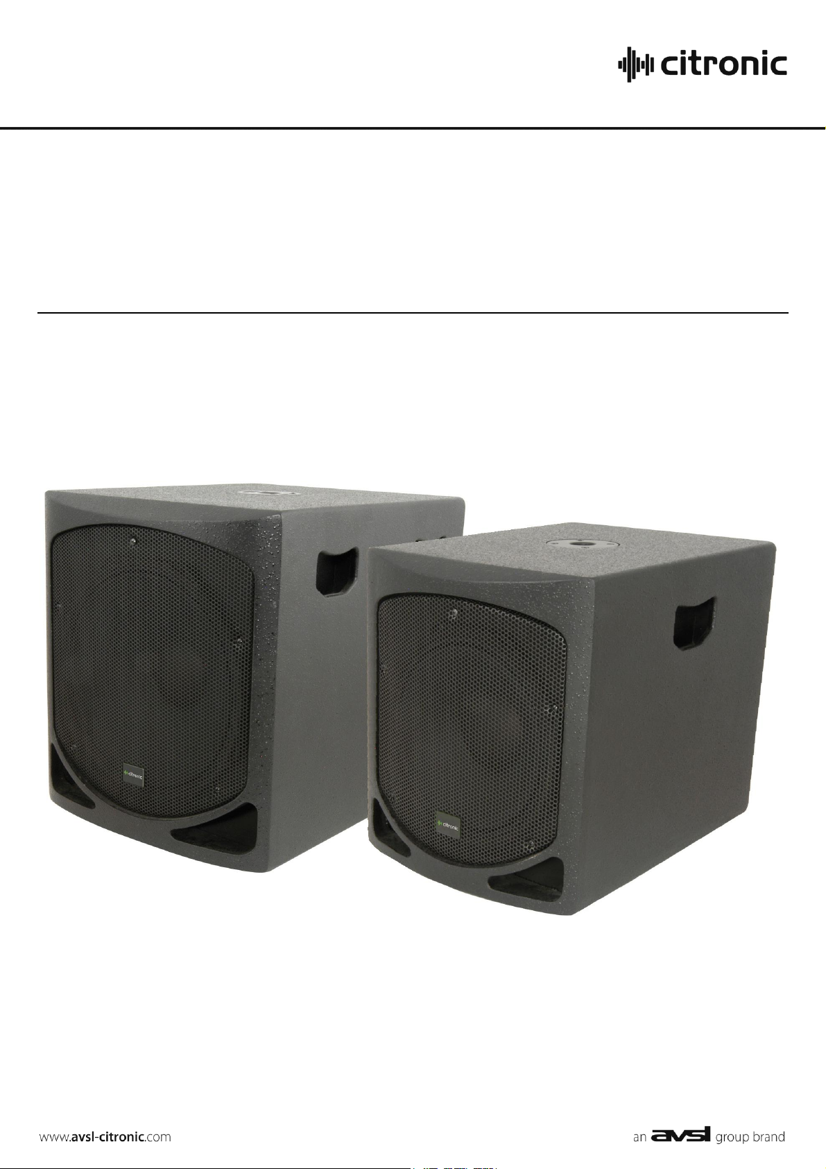
CLB12A, CLB15A
ACTIVE SUBWOOFERS
Order ref: 178.271, 178.273
User Manual
Page 2

Introduction
1. INPUT LEVEL
Varies the gain of L+R line inputs
2. PHASE
Press in to invert the signal polarity
3. FREQUENCY
Adjusts cutoff frequency of sub filter
4. L+R LINE OUTPUTS
XLRM connectors for parallel connection to
further active speakers or amps
5. L+R LINE INPUTS
Combo XLR/Jack connectors for Left + Right
line inputs (summed together for sub signal)
6. COOLING FAN
Air vent for cooling fan – do not cover or block
7. GND/LIFT
Ground lift switch for venues with noisy mains.
Switching to LIFT isolates signal ground from
mains earth
8. POWER
Power on/off switch and indicator
9. MAINS INLET
Combined IEC inlet and fuse holder
Thank you for choosing the Citronic CLB-series active subwoofer as part of your sound reinforcement system. Please read this manual
fully and follow the instructions to achieve the best results with your new purchase and to avoid damage through misuse.
Unpacking
Your CLB active subwwofer should reach you in good condition and be supplied with the appropriate mains power lead(s).
If there is any damage or items missing, contact your retailer immediately.
Warning
To prevent the risk of fire or electric shock, do not expose any of the components to rain or moisture.
If liquids are spilled on the panel, disconnect mains and allow unit to dry out & have checked by qualified personnel before further use.
Avoid impact or extreme pressure to the cabinet, panel or grille
No user serviceable parts inside – Do not open the case – refer all servicing to qualified service personnel.
Safety
Check for correct mains voltage and condition of IEC lead before connecting to power outlet
Ensure signal leads are good condition with no short connections or damaged plugs
Placement
Position on a stable, strong surface with the grille facing towards listeners
Keep away from heat sources and away from damp or dusty environments
Ensure adequate access to controls and connections
Cleaning
Use a soft dry or slightly damp to clean the cabinet as required. Do not use strong solvents for cleaning the unit
Amplifier Panel
CLB Active Subwoofer User Manual
Page 3

Connection
Connect balanced or unbalanced line level signal(s) from sound source or audio mixer to the L+R combo inputs using good quality XLR
or 6.3mm jack leads. Connecting to either of these will work for a mono input.
Connect the OUTPUT XLR to any further active speakers or amplifiers that are to be fed the same signal.
Connect the supplied mains cable from the IEC connector to a suitable mains outlet, ensuring correct voltage and adequate current
capacity.
Operation
With the INPUT LEVEL control (1) turned fully down, switch on the power switch (8). The power LED will illuminate.
Ensure a signal is playing to the input(s) and gradually increase the INPUT LEVEL control (1) until the required output volume is
reached.
The power LED doubles as a clip indicator, turning to red when the amplifier signal is clipping. It is OK for the clip indicator to light red
momentarily on peaks in the audio but if the LED shows red for longer periods, it will be necessary to turn down the input level.
Adjusting the FREQUENCY control (3) varies the cutoff frequency of the high cut filter. Rotate left for lower frequency and right for
higher frequency. Remember that lower frequency settings will cut out more of the mid frequencies and input level may need to be
increased to compensate.
The INV switch reverses polarity when pressed in, which may help to avoid low frequency feedback or phase align 2 subs facing
toward each other. The correct setting for this switch is whichever produces the best output or lowest feedback and is subject to trial
and error.
The GND/LIFT switch can be used if there is noise introduced into the signal from a poor mains earth.
Otherwise, the best position for this switch is GND, which connects signal ground to mains earth.
Before powering down, turn the channel gain controls fully down to avoid loud noises when switching off.
CLB Active Subwoofer User Manual
Page 4
Specifications
Model
CLB12A
CLB15A
Power supply
230Vac, 50Hz (IEC)
Pole Mount
35mm cast metal socket
Input connection
Balanced or unbalanced line L+R combo connectors (6.3mm jack/XLRF )
Output connection
Balanced or unbalanced line L+R XLRM connectors (parallel to input)
Driver
300mm (12”) reinforced paper cone
380mm (15”) reinforced paper cone
Impedance
4Ω
Driver: Coil size
76mm (3“)
76mm (3“)
Driver: Basket
Die-cast aluminium frame
Die-cast aluminium frame
Output power: RMS
400W
500W
Frequency response (-3dB)
40Hz - 180Hz
35Hz - 180Hz
Crossover frequency
40Hz - 150Hz
40Hz - 150Hz
Sensitivity (1m, 1W)
100dB
105dB
Maximum SPL
120dB
129dB
THD
<1%
<1%
Dimensions
445 x 525 x 575mm
510 x 595 x 655mm
Weight
24kg
28kg
No power light on rear panel switch
Ensure IEC inlet is connected to mains and mains lead is in good condition
Ensure mains outlet is switched on
Check mains fuse. If repeatedly blowing, refer to qualified service
personnel
Power light is on but no other LEDs and no output
Check input signal and connection leads
Ensure input level and frequency controls are not turned fully down
Humming noise without any signal present
Test the GND/LIFT switch and check if the noise is from mains earth
Check integrity of signal leads and ensure they are well screened
Output very distorted and/or power LED is
frequently red
Turn down the input level rotary or output level from the audio source
Adjust the cutoff to a lower frequency
Output is working but at very low level
Ensure input source is at line level
Test the phase switch and check if one setting is louder than the other
Increase input level control or output level from audio source
Adjust the cutoff frequency upward to allow some more mid-range into the
signal
Troubleshooting
Errors and omissions excepted.
Copyright© 2013. AVSL Group Ltd.
CLB Active Subwoofer User Manual
 Loading...